How Many Amps Should a Well Pump Draw? A Safe Model-Specific Check
Use the motor and control nameplate, voltage, startup behavior, and stabilized conductor readings to triage a well-pump current concern safely.
The short answer
There is no universal amp number for a well pump. Compare stabilized current with the exact motor’s nameplate or manufacturer table after recording voltage, horsepower, phase, 2-wire or 3-wire setup, and control-box type. Startup current is a separate observation. Current can point to low voltage, control, cable, pump, or well conditions, but it cannot prove a failed pump remotely. Do not open energized controls or test live wiring as a homeowner.How Many Amps Should a Well Pump Draw? A Safe Model-Specific Check
There is no universal “normal” amp number for a well pump. The defensible comparison is the stabilized current for your exact motor and control setup, measured with the voltage and conductor location recorded. Horsepower and voltage charts can be useful orientation, but they do not account for motor design, 2-wire versus 3-wire wiring, control-box or drive settings, cable length, pump load, head, or the difference between startup inrush and running current.
Use this page to build a service record, not to declare a pump failed. A high, low, or uneven reading can point toward voltage, control, cable, pump, well, or system conditions. It does not identify the failed part by itself.
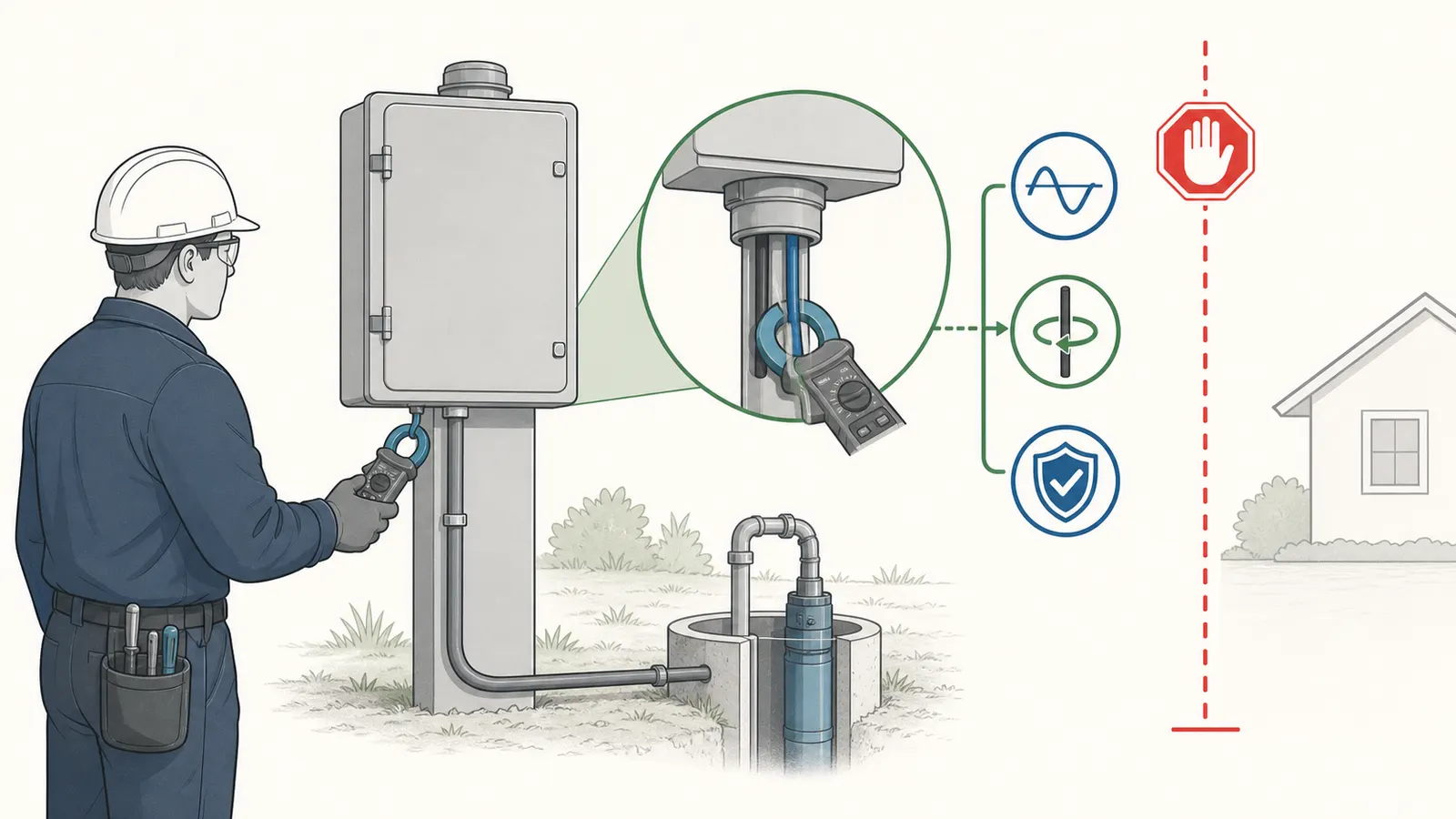
Hard safety stop: Do not open an energized control box, test live wiring, open a well, pull a pump, enter a well pit or other confined space, or manipulate pressurized pump, tank, relief-valve, or pressure-switch equipment for this worksheet. Pentair’s manual warns of hazardous voltage, says wiring should be done by a qualified electrician, and says power must be disconnected before work on the pump, motor, or tank. Pentek Electronics Installation, Operation, and Maintenance Manual PN793
The homeowner-safe work here is limited to reading labels from a dry, safe position, recording pressure and cycling symptoms, photographing accessible identification plates without removing covers, and handing the worksheet to a qualified well-pump professional. Any voltage or current measurement at a control box belongs to a person qualified and equipped to do that work.
“Qualified professional” is a safety handoff, not a legal designation. Licensing, certification, bonding or insurance, permits, inspections, and who may perform electrical, well-pump, or pressure-system work vary by state and locality. Before arranging or authorizing service, verify the applicable requirements with the state or local licensing and permitting office and the authority having jurisdiction (AHJ), and ask the contractor which credentials and permits apply. The U.S. Department of Energy describes an AHJ as the official or equivalent qualified person designated in a state or municipality to interpret applicable electrical requirements, and warns that requirements can vary by location. DOE Electrical Safety Handbook: AHJ and local requirements EPA’s advice to use bonded and insured installers and, where required, licensed and certified installers does not create a nationwide license rule or authorize a particular person to work on your system. EPA: Learn About Private Water Wells
The U.S. Environmental Protection Agency describes submersible pumps as equipment placed inside the well casing and advises well owners to verify that pump-well installers are bonded and insured and, where required, licensed and certified. EPA: Learn About Private Water Wells That supports treating pump access, wiring, and removal as professional work rather than a homeowner amp experiment.
1. Start with the exact motor and control record #
The first question is not “How many amps does a 1-horsepower pump draw?” It is “Which motor, at which voltage and frequency, connected through which control system, is installed here?” The answer lives on the motor nameplate, control-box label, drive display or label, pump documentation, and installation record.
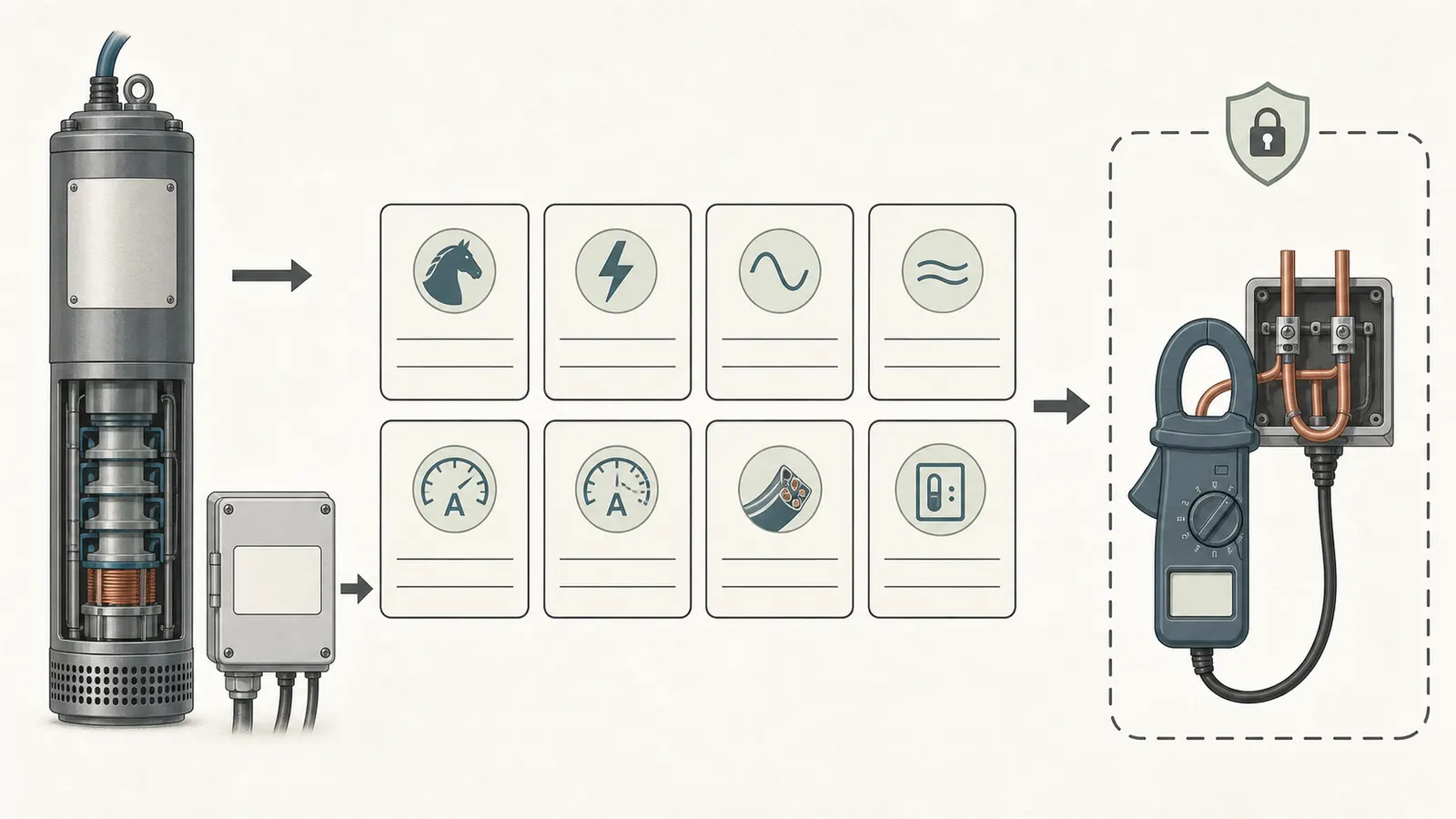
Record these fields before discussing amps
| Field | Write down exactly | Why it changes interpretation |
|---|---|---|
| Motor manufacturer and part number | ____________________ | Manufacturers use different motor designs and reference tables. |
| Pump manufacturer and model | ____________________ | The motor does not establish the pump’s hydraulic load by itself. |
| Horsepower | ______ HP | Horsepower is an input to the lookup, not an amp answer. |
| Rated voltage | ______ V | Current and permissible voltage depend on the rated voltage. |
| Frequency and phase | ______ Hz; 1φ / 3φ | A 60-Hz single-phase setup is not interchangeable with another configuration. |
| Motor type | 2-wire / 3-wire / 3-phase / drive-controlled | Lead behavior and the correct reference amp value can differ. |
| Nameplate FLA, RLA, or service-factor amps | ______ A | Record the label’s abbreviation; do not silently substitute one rating for another. |
| Control-box or drive manufacturer and model | ____________________ | Relays, capacitors, overload settings, and drives affect how current is delivered and interpreted. |
| Control-box rating and configuration | ______ HP / ______ V / QD / CRC / standard / deluxe / other | A box must be matched to the motor and installation. |
| Pressure switch or drive setpoint | ______ cut-in / ______ cut-out or ______ PSI | Pump load and observed symptoms change with operating pressure. |
| Cable or drop-cable length, if known | ______ ft | Cable resistance can create voltage drop between the source and motor. |
| Source of each number | nameplate / manual / service record / observed | Keeps evidence separate from assumptions. |
Pentair’s motor nomenclature shows why the label matters: its covered motors encode motor size, horsepower, frequency, voltage, and phase, and the manual includes separate two-wire, three-wire, and three-phase categories. Its electrical tables list different values for specific motor part numbers rather than one universal number for an entire horsepower class. Pentek PN793 motor nomenclature and electrical parameters
The same caution applies to control boxes. Franklin describes its control boxes as engineered for specified Franklin three-wire, single-phase motor ranges and separates QD, CRC, standard, and deluxe products with different voltage and horsepower listings. That product-family information is evidence that “a 230-volt box” is not enough to prove compatibility. Franklin Water motor control boxes
Pentair likewise states in its control-box documentation that the cited boxes are designed for motors with the same horsepower and voltage ratings and should not be used with motors having different ratings. Treat that as equipment-specific compatibility guidance, not as permission to replace a box based on a photo or a generic online chart. Pentair control-box compatibility statement
FLA, RLA, service-factor amps, and “running amps” are not interchangeable labels
Your nameplate or manual may use FLA, RLA, SFA, SF amps, or another manufacturer-specific term. These abbreviations are not interchangeable: a university motor-label reference describes FLA as full-load amps, RLA as running-load amps, and SFA as service-factor amps, while noting that motor labels are not well standardized. Franklin’s VFD note also gives FLA and SFA as separate values for one motor example. Copy the label exactly, including whether the value is tied to a particular lead, control mode, phase, or service-factor condition. Do not turn a service-factor value into a promise that the pump should run at that amperage all the time. Mississippi State University motor-label reference Franklin: Quickly Service a VFD
In the Pentair drive setup, the correct service-factor-amp entry differs by motor arrangement: the manual says a one-phase three-wire motor uses the capacitor-start/capacitor-run reference, while a one-phase two-wire or three-phase motor uses the motor nameplate service-factor-amp rating. Pentair service-factor-amp guidance The exact point is not that one label is “better”; it is that the reference must match the motor and controller.
2. Separate startup inrush from stabilized running current #
A pump motor can draw a brief startup surge that is materially different from its settled current. Comparing a meter’s first instant of startup with a running-amp specification is an apples-to-oranges comparison.
Pentair explains that starting a motor at full voltage can spike load current and bring the motor to full speed in less than one-half second in the cited motor-starting discussion. The manual also notes that the startup event can produce a brief voltage dip elsewhere in the system. Pentair motor-starting guidance
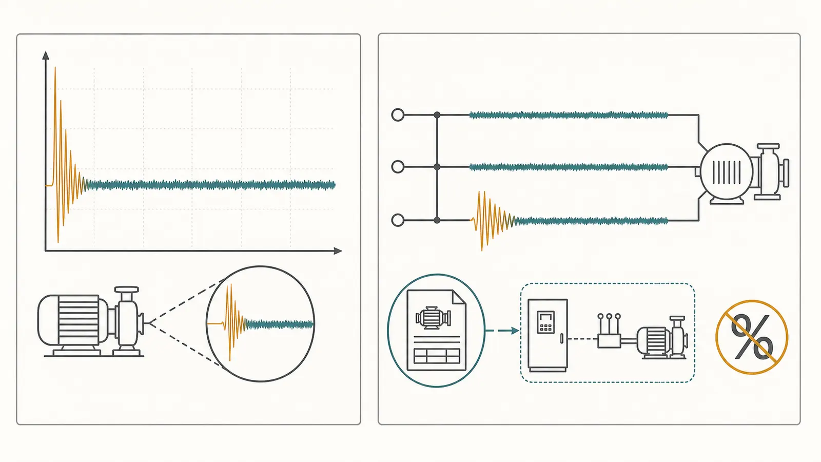
Record two different observations:
- Startup behavior: Does the pump start promptly, and does the initial current event settle as expected for the exact motor and control system?
- Stabilized behavior: After the pump is running normally and the system is at a comparable operating point, what is the current on the specified conductor or phase?
Do not average the surge into the running value. Do not use a brief spike to claim the motor is overloaded. Do not use a calm-looking running value to claim the start circuit, relay, capacitor, or mechanical load is healthy.
A three-wire motor has more than one useful current observation
For a single-phase three-wire submersible setup, the start and run paths can have different roles. The BCcampus/OpenText rural-water-supply chapter gives a technical example in which current in the red start lead is momentarily high and then drops within one second to the manufacturer’s specification, while the black and yellow lead readings should not exceed their specifications. It also connects a persistent high start-lead current with relay or switch problems and describes how an open run capacitor can make black and yellow current higher than normal while red-lead current is lower than normal. OpenText current-measurement guidance
That one-second behavior is not a universal timing promise for every motor, relay, solid-state control, or variable-frequency drive. It is a model- and arrangement-dependent comparison point. The technician must use the exact motor and control documentation.
A two-wire motor does not give you the same lead pattern
A two-wire, single-phase motor has a different control arrangement from a three-wire motor. A three-phase motor has three phase conductors and a separate phase-balance question. A variable-frequency drive also creates separate records: Franklin says its fault history shows the amperage at the time of a fault and the speed in hertz, while the drive uses the configured motor amps to calculate overload protection. Record whether a value came from an external meter, a live display, or fault history; do not compare those records as if they were the same measurement. Franklin: Quickly Service a VFD
Write the configuration in large letters on the worksheet before any reading is discussed:
Configuration: 2-wire / 3-wire / 3-phase / VFD or drive-controlled
Reading location: ____________________
Conductor or phase identified: ____________________
Startup recorded separately? yes / no
Stabilized reading recorded separately? yes / no
If a service person cannot tell which conductor was measured, the number is incomplete. Fluke explains that opposing currents can cancel when more than one conductor is inside a clamp, producing a zero or erroneous result; the intended current measurement uses one conductor at a time. Fluke: Clamp Meter Readings—Problems and Solutions This is a qualified-service measurement method, not a homeowner instruction to open a control box.
3. Put voltage, head, and control settings beside the amp number #
Current is a response to the whole operating system. Franklin’s VFD troubleshooting guidance says the pump loads the motor, that moving more water increases motor load, and that high pump flow can produce high amps while reduced flow can produce underload. Pressure, flow, speed, and control settings therefore belong beside the current record; a motor’s current cannot be interpreted without voltage and operating conditions. Franklin: Quickly Service a VFD
Check the voltage reference, not just the label on the breaker
The technical sequence described by OpenText starts with the motor off, then checks supply voltage at the pressure switch or line contactor, and checks voltage again at the load side while the pump is running normally. The text says the running voltage should remain essentially the same except for a slight starting dip and identifies loose connections, bad contacts, ground faults, and inadequate supply as possible causes of excessive voltage drop. OpenText voltage-measurement sequence
Pentair’s own motor guidance says the nameplate voltage must match the available supply and remain within plus or minus 10 percent for the covered motor families. This is a manufacturer-specific operating criterion, not a national rule for every pump. Pentair nameplate-voltage requirement
For a simple math illustration, plus or minus 10 percent around a 230-volt nameplate is 207 to 253 volts. That arithmetic does not tell you what your pump is receiving, and it does not authorize a homeowner to test an energized panel. A qualified person should record the actual voltage, whether the pump was starting or stabilized, and where the probes were placed.
Head and pressure can move the current without changing the motor
“Head” is the resistance the pump works against: elevation, pressure, pipe friction, valves, filters, and the pump’s operating point all contribute. A pump at shutoff pressure is not operating at the same point as a pump delivering water to a fixture. A clogged filter, closed valve, failed check valve, low well level, or changing demand can alter the hydraulic condition even if the nameplate never changes. OpenText pump-current troubleshooting examples
The OpenText troubleshooting chapter lists a bound pump as a cause of locked-rotor amps and overload tripping, but it also lists shut-off pressure, a worn pump, or stripped drive-shaft splines as possible causes of low amps. OpenText pump-current troubleshooting examples That is the central reason this page treats current as triage: both high and low readings can be associated with more than one physical condition.
A useful service record pairs the current with:
- pressure before the pump starts, if visible on a safe, intact gauge;
- cut-in and cut-out or drive setpoint, if documented;
- whether a faucet, irrigation zone, or appliance was using water;
- whether the pump reached pressure and stopped;
- whether flow was weak, absent, surging, sandy, or discolored;
- whether the pump started once, repeatedly, or ran continuously;
- whether the breaker, fuse, overload, or pump protector tripped.
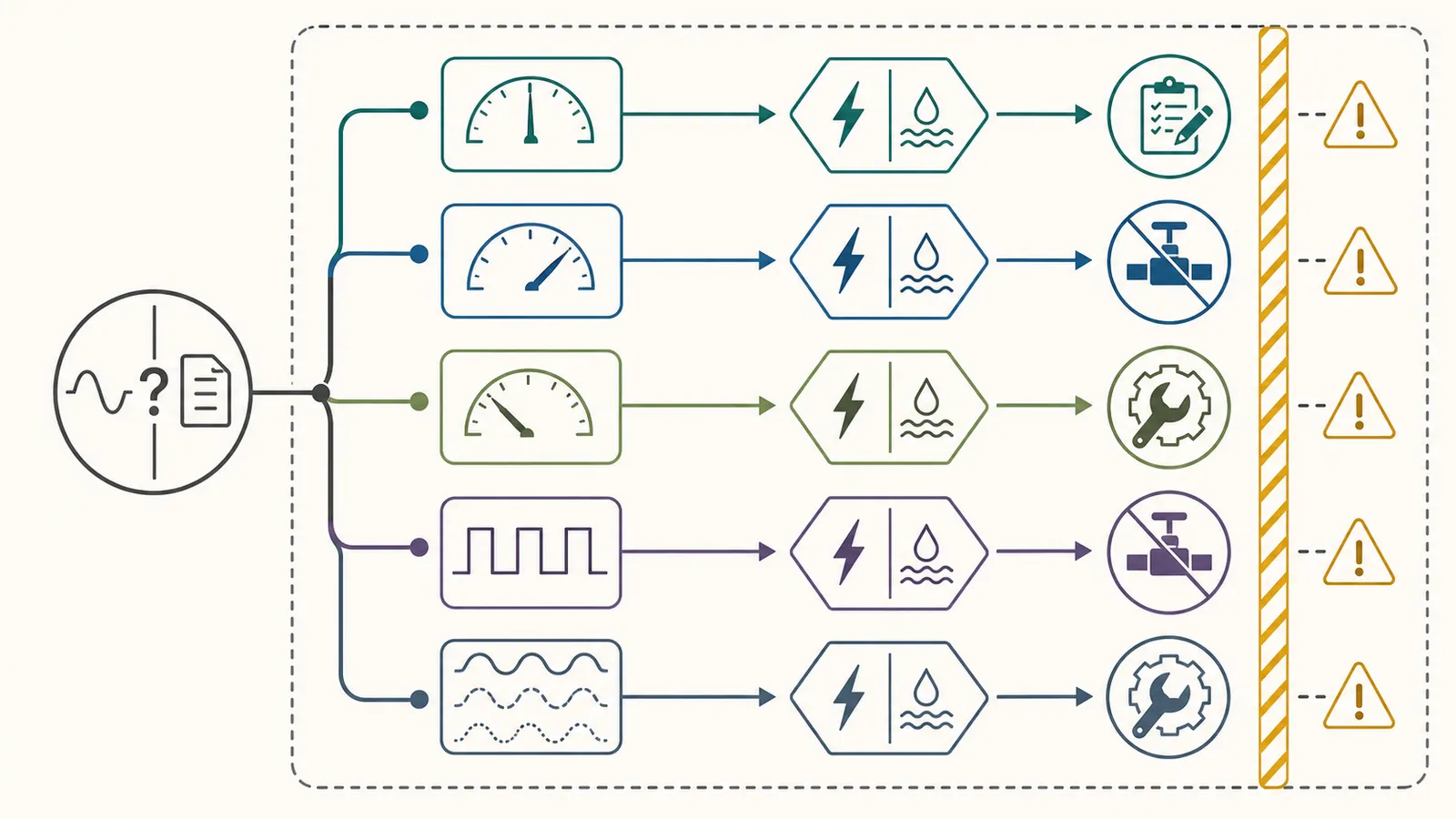
Do not change the pressure switch, tank precharge, drive settings, valve position, cable, control box, or pump based on an amp number alone. These are system settings or energized equipment, not homeowner calibration steps.
Control-box design changes the meaning of a reading
A capacitor-start, capacitor-run, standard relay, quick-disconnect relay, solid-state control, and variable-frequency drive do not present the same starting behavior. The control component may be matched to a motor’s horsepower and voltage, and the manufacturer may define a lead-specific value rather than one number for the whole assembly.
Franklin’s control-box page describes QD relays, CRC boxes with a run capacitor, and standard or deluxe boxes for larger three-wire single-phase water systems. The page also gives separate rating tables by box type, voltage, and horsepower. Franklin control-box product and rating tables
That is why a replacement decision should use the exact motor part number, box part number, voltage, horsepower, wiring arrangement, and manufacturer table. A generic “1 HP 230 V” chart can hide a control mismatch.
4. Use the worksheet as a qualified-service measurement record #
This is the practical decision surface. The homeowner can fill the identity, symptoms, and safe observations. A qualified service person can complete the electrical fields. Keep the two parts visibly separate.
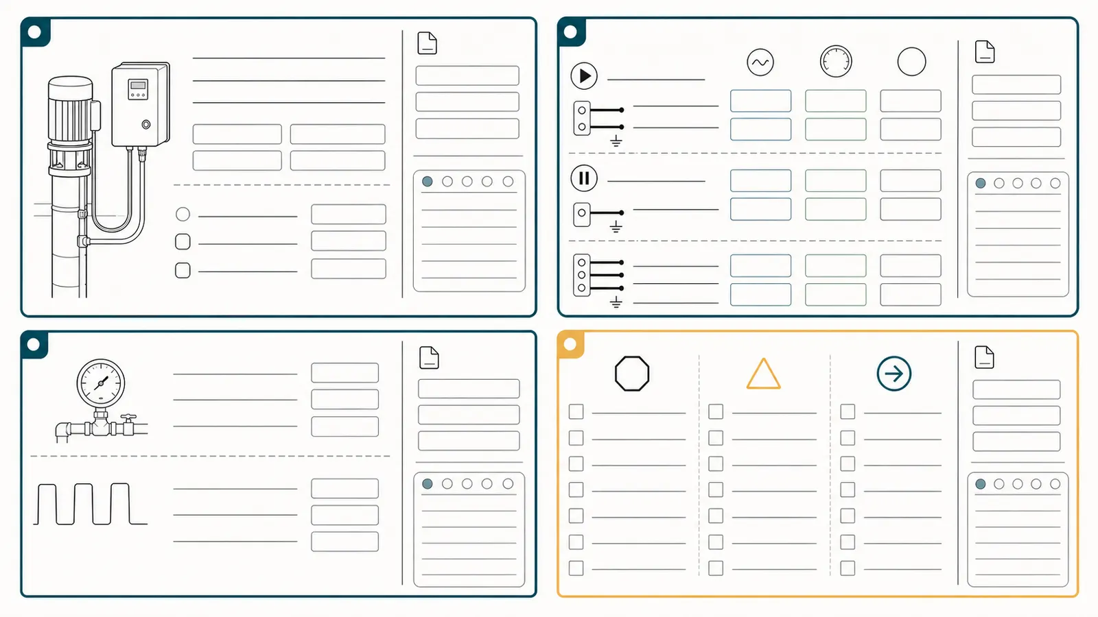
Part A — homeowner-safe identity and symptom record
| Observation | Entry |
|---|---|
| Date and time | ______________________________ |
| Well-pump motor label photographed from safe position | yes / no |
| Control-box or drive label photographed without opening cover | yes / no |
| Motor model and part number | ______________________________ |
| Pump model and part number | ______________________________ |
| Horsepower / voltage / Hz / phase | ______________________________ |
| 2-wire, 3-wire, 3-phase, or drive-controlled | ______________________________ |
| Control-box or drive model | ______________________________ |
| Pressure gauge reading before start, if safely visible | ______ PSI |
| Pressure gauge reading after stop, if safely visible | ______ PSI |
| Pump starts promptly | yes / no / unknown |
| Pump reaches shutoff and stops | yes / no / unknown |
| Pump runs continuously | yes / no / intermittent |
| Pump cycles too often | yes / no / unknown |
| Breaker, fuse, overload, or protector trips | yes / no / unknown |
| Flow symptom | weak / no water / air / surging |
| Water appearance or odor | clear / sandy / discolored / unusually odorous |
| Water-safety next action | if discolored, unusually odorous, after flooding, or contamination is suspected: stop drinking and cooking use; contact the local health department or a certified drinking-water laboratory |
| Other water use during observation | ______________________________ |
| Safe next action | record only / stop use if unsafe / call qualified service |
Water safety is separate from pump current
Sand, discoloration, or an unusual odor may be a useful symptom to record, but an amp reading cannot establish that well water is safe. Brictale’s conservative household policy is to stop drinking and cooking use if water is discolored, unusually odorous, follows flooding, or contamination is suspected, and to use bottled water or another known-safe source until the local health department or a certified drinking-water laboratory advises otherwise. That broader stop is Brictale’s safety policy; it is not a claim that CDC or EPA treat every appearance or odor change as confirmed contamination. CDC recommends testing when well water’s color, taste, or smell changes or flooding affects the area, using a state-certified laboratory and contacting the health department for interpretation and next steps. CDC: Guidelines for Testing Well Water EPA likewise directs well owners to test after flooding or a change in odor, color, or taste and to use certified drinking-water laboratories. EPA: Protect Your Home’s Water
Part B — electrical record for the qualified person
| Measurement | Startup or stabilized? | Location and conductor | Reading | Manufacturer reference | Notes |
|---|---|---|---|---|---|
| Supply voltage | __________________ | __________________ | ____ V | ____ V | Pump off / starting / running |
| Load-side voltage | __________________ | __________________ | ____ V | ____ V | Location: __________________ |
| Current lead or phase 1 | __________________ | __________________ | ____ A | ____ A | 2-wire / 3-wire / 3-phase |
| Current lead or phase 2 | __________________ | __________________ | ____ A | ____ A | __________________ |
| Current lead or phase 3 | __________________ | __________________ | ____ A | ____ A | __________________ |
| Start-lead observation, if applicable | __________________ | __________________ | ____ A | ____ A | Time to settle: ______ |
| Control or drive fault code | n/a / ______ | Display / record | ______ | Manual page: ______ | __________________ |
| Measurement instrument and date of calibration, if tracked | n/a | __________________ | __________________ | __________________ | __________________ |
| Measured by | n/a | Name / company | __________________ | __________________ | __________________ |
The worksheet should preserve the source of the reference value: nameplate, exact manual page, manufacturer support table, or a qualified service record. If the reference is unknown, write “unknown” instead of borrowing a number from a similar pump.
Measurement location matters
For a three-wire example, OpenText describes recording current on individual motor leads at the control box or starter. For three-phase current, it describes recording each leg, calculating the average, and comparing each leg with that average. OpenText conductor and phase measurement method
This is not an instruction for a homeowner to place a clamp meter in an energized box. It is a record format for qualified service work. The professional should document whether the reading was made before or after the control, on which conductor, under what pressure and flow condition, and whether other loads were active.
5. Interpret the record without overdiagnosing #
The table below is a triage matrix. “Possible direction” is not a diagnosis. Each branch needs the exact motor documentation and, where the work is electrical, qualified service.
| What the record shows | What it can suggest | What it does not prove | Safest next step |
|---|---|---|---|
| Stabilized current is within the exact manufacturer reference and pressure behavior is normal | The observed operating point is consistent with the documentation | That the pump will remain healthy or that every start component is good | Save the record; monitor pressure, cycling, and future changes. |
| High current on the relevant lead or phase with voltage low or falling under load | Supply, connection, cable, or voltage-drop concern | That the motor itself is failed | Stop homeowner testing; have a qualified person verify voltage at the correct points and inspect the circuit. |
| High current with normal documented voltage | Possible hydraulic overload, bound pump, mechanical drag, control issue, or wrong reference | Which part is responsible | Have the professional compare current, pressure, flow, motor data, and control compatibility. |
| Low current with weak flow or inability to build pressure | Possible shutoff condition, worn pump, stripped coupling, low-water or well condition, or another hydraulic problem | That the pump is drawing “safely” or that it should be replaced | Record symptoms and operating pressure; arrange qualified pump-system diagnosis. |
| Three-wire start lead stays high rather than settling as the exact manual expects | Possible relay, switch, capacitor, or control behavior issue | A failed control part without testing | Turn over the lead-specific record to a qualified technician; do not open the box. |
| Black or yellow run-lead current exceeds its reference while the start-lead pattern is abnormal | Possible capacitor or control problem in the cited three-wire example | That the motor is bad | Verify the exact motor/control model and have the professional test the control components. |
| Three-phase currents differ substantially or calculated unbalance exceeds the exact limit | Voltage imbalance, starter contacts, loose terminals, cable, winding, or pump concern | The source of the imbalance | Qualified service should check voltage balance and connections before changing phase wiring or pulling equipment. |
| Breaker or overload trips at start or after running | Possible wrong voltage, incorrect protection or connections, locked rotor/pump, cable insulation, sand, or other motor/system fault | The breaker is “too small” or the pump must be replaced | Leave protective devices in place; stop repeated resets and obtain professional diagnosis. |
| Current looks normal but pump runs continuously or pressure is poor | Possible leak, check-valve, tank, control, pump, or well-yield issue | That current clears the pump | Use the symptom record and pressure observations; current is only one input. |
Franklin’s accessible VFD troubleshooting guidance is useful as a boundary against single-cause thinking. It lists heat from insufficient cooling flow, improper voltage, current unbalance, mechanical drag, high pump flow, and a bad motor among possible directions for high-amp or overload behavior; it also explains that reduced flow can produce an underload. These are investigation paths, not a remote diagnosis. Franklin: Quickly Service a VFD
Three-phase imbalance calculation
If a qualified professional records three phase values, the worksheet can show the calculation transparently:
average current = (phase 1 + phase 2 + phase 3) ÷ 3
percent unbalance = greatest absolute difference from average ÷ average × 100
For a clearly labeled arithmetic example, readings of 54 A, 55 A, and 60 A give an average of about 56.3 A. The greatest difference is about 3.7 A, so the calculated unbalance is about 6.6 percent. Those numbers are the example published in the OpenText chapter, not a measurement of your pump. The chapter says to check voltage balance first when unbalance exceeds 5 percent and lists starter contacts, loose terminals, cable defects, motor windings, and pump damage as possible directions. OpenText three-phase example
Pentair’s PN793 manual presents its five-percent current-unbalance limit in the general “Three-Phase Current Balancing” test, which directs the reader to measure each power lead and calculate unbalance. The same manual separately gives a less-than-five-percent criterion for phase-converter applications. Because the limit and test sequence remain equipment- and application-dependent, use the exact motor and control documentation when references differ. Pentair PN793: three-phase current balancing and phase-converter guidance
6. Decide whether to monitor, stop, or escalate #
The right output of an amp check is a bounded next action.
Monitor and preserve the record when all of these are true
- The exact motor, voltage, frequency, phase, and control configuration are identified.
- The reference current comes from that motor’s nameplate or manufacturer documentation.
- A qualified person recorded the correct conductor or phase and separated startup from stabilized current.
- Voltage was documented under a comparable running condition.
- Pressure and cycling behavior are normal for the home.
- There is no overheating, repeated tripping, burning odor, exposed wiring, flooding, or unexplained continuous operation.
Even then, “consistent with the reference” is not the same as “proven healthy.” Save the service record and compare future readings only when the operating conditions are comparable.
Stop repeating tests and escalate promptly when any of these are true
- The breaker, fuse, overload, or pump protector trips.
- The motor hums, stalls, starts slowly, or restarts repeatedly.
- The pump runs continuously, cannot reach pressure, or pressure falls unexpectedly.
- Voltage is outside the exact manufacturer range or changes substantially at startup.
- One conductor or phase is far from the others.
- The control-box model does not match the motor’s horsepower, voltage, or wiring arrangement.
- The pump is in a well, pit, wet area, confined space, or location with exposed electrical hazards.
- The only available measurement would require removing a cover, disconnecting a conductor, opening a well, changing a setting, or touching pressurized equipment.
Repeated breaker resets or repeated starts can turn a symptom into equipment damage. Leave protective devices in place and arrange qualified service. Do not “test” a suspected locked rotor by repeatedly cycling power.
Stop water use or shut down only through a safe, known control when there is an immediate hazard
If water is discolored, unusually odorous, follows flooding, or contamination is suspected, apply Brictale’s conservative water-safety policy independent of the amp result: do not use the water for drinking or cooking until the local health department or a certified drinking-water laboratory advises otherwise. Current readings cannot clear the water. Use bottled or another known-safe source while seeking guidance. CDC’s separate emergency guidance applies when a private well is or may be contaminated with harmful germs or chemicals. CDC: Well Water Safety
If there is flooding near electrical equipment, a burning smell, smoke, arcing, a damaged enclosure, exposed conductors, or a failed pressure-relief condition, move people away and use emergency services or qualified electrical/well-pump help as appropriate. Do not enter water near electrical equipment and do not open the box to investigate.
If the system is simply producing no water without an immediate electrical or flooding hazard, document the last normal pressure and pump behavior. A professional can often use that timeline, the labels, and the service history to choose a safer test sequence.
7. Hand the professional a decision-ready packet #
The most valuable output is not a verdict such as “the pump is drawing too many amps.” It is a compact record that lets the next person see what was identified, what was observed, and what remains unknown.
Include:
- clear photographs of the motor, pump, control-box, drive, pressure switch, and pressure-tank labels taken without opening or disturbing equipment;
- exact model and part numbers, not only horsepower and voltage;
- the motor’s FLA, RLA, service-factor, or other printed amp labels exactly as written;
- 2-wire, 3-wire, three-phase, or drive-controlled configuration;
- control-box or drive model, rating, and any displayed fault code;
- startup and stabilized readings in separate fields;
- the conductor or phase measured and the measurement location;
- voltage, pressure, flow, cycling, and water-use conditions during the reading;
- whether the system reached pressure and stopped;
- breaker, overload, pump-protector, or relay behavior;
- prior repairs, pump replacement date, well work, generator use, lightning event, or wiring changes;
- the page or URL used for every manufacturer reference value.
The professional may still need to verify voltage, current, winding resistance, insulation, controls, pump performance, well conditions, and hydraulic behavior. OpenText lists line-to-line voltage, current in motor wires, insulation resistance, and winding resistance among preliminary troubleshooting tests before removing a motor, but it also describes hazardous procedures that require power isolation and appropriate instruments. OpenText preliminary troubleshooting tests This article deliberately stops before those tests.
The homeowner decision is therefore straightforward:
- Identify the exact equipment.
- Separate startup from stabilized current.
- Record voltage and the correct conductor or phase.
- Pair amps with pressure, flow, and cycling symptoms.
- Treat current as triage, not proof of a failed pump.
- Escalate any energized, pressurized, submerged, confined-space, or pump-removal work to a qualified professional.
That record is more useful than a generic amp chart because it preserves the variables that determine whether a reading means anything at all.
Cite this guide
Brictale. “How Many Amps Should a Well Pump Draw? A Safe Model-Specific Check.” Published 2026-09-07; updated 2026-09-07.
https://brictale.com/water/pumps/how-many-amps-should-a-well-pump-draw · Read the Markdown version
Sources and scope
Evidence behind this page
- For the Pentek motor family covered by the manual, the motor nameplate voltage must match the available supply and the supply must remain within plus or minus 10 percent of the rated voltage.
Pentek Electronics Installation, Operation, and Maintenance Manual PN793
Pentair PN793 guidance for the motor families and drives covered in that manual; it is not a universal electrical-code tolerance for every pump or installation.
Accessed · Link to this claim - Pentair states that starting a motor at full voltage can spike load current and that the motor reaches full speed in less than one-half second in the cited discussion.
Pentek Electronics Installation, Operation, and Maintenance Manual PN793
The cited startup behavior is from Pentair's motor-starting discussion; it does not establish an amp value or timing rule for every motor design.
Accessed · Link to this claim - Pentair distinguishes one-phase two-wire and one-phase three-wire motors and says the correct service-factor-amp reference differs: three-wire motors use the capacitor-start/capacitor-run value in the cited drive setup, while two-wire motors use the motor nameplate service-factor-amp rating.
Pentek Electronics Installation, Operation, and Maintenance Manual PN793
Pentair Intellidrive setup guidance; configuration and terminology must be verified against the installed motor and controller.
Accessed · Link to this claim - Pentair states that the cited control boxes are designed for Pentair motors with the same horsepower and voltage ratings and should not be used with motors having different ratings.
Pentek Electronics Installation, Operation, and Maintenance Manual PN793
The compatibility statement appears in the Pentair control-box drawing section; it is not a blanket compatibility rule for other manufacturers.
Accessed · Link to this claim - Franklin's VFD troubleshooting guidance lists insufficient cooling flow, improper voltage, current unbalance, mechanical drag, high pump flow, and a bad motor among possible directions for high-amp or overload behavior; it also explains that reduced flow can produce an underload.
Quickly Service a VFD: Troubleshooting the Top 5 Most Common Challenges
Franklin Electric field-service guidance for VFD-controlled pumping systems; these are possible causes to investigate, not a remote diagnosis of a particular pump or a universal amp limit.
Accessed · Link to this claim - Franklin says a VFD fault history can show amperage at the time of a fault and speed in hertz, while configured motor amps are used to calculate overload protection; it also says motor load increases with water moved and that high flow can cause high amps while reduced flow can cause underload.
Quickly Service a VFD: Troubleshooting the Top 5 Most Common Challenges
Franklin Electric discussion of VFD fault records, motor settings, and pump loading; the record types and operating conditions must be identified before comparing values.
Accessed · Link to this claim - Franklin publishes separate full-load amps and service-factor amps for the same motor model, and its VFD guidance separately refers to FLA and SFA when discussing underload and overload settings.
Quickly Service a VFD: Troubleshooting the Top 5 Most Common Challenges
Franklin Electric example and terminology; it does not define every manufacturer’s FLA, RLA, or SFA label.
Accessed · Link to this claim - A U.S. university motor-label reference describes FLA as full-load amps, RLA as running-load amps, and SFA as service-factor amps, and notes that motor labels are not well standardized.
Mississippi State University Industrial Assessment Center training reference; abbreviations and the controlling reference remain manufacturer- and model-specific.
Accessed · Link to this claim - Fluke says a clamp meter should enclose one phase conductor at a time because opposing magnetic fields can cancel when multiple conductors are inside the clamp, producing a zero or erroneous result.
Clamp Meter Readings: Problems and Solutions
Fluke clamp-meter measurement guidance; it describes instrument method and does not authorize a homeowner to access energized pump controls.
Accessed · Link to this claim - Franklin describes its submersible control boxes as optimized for Franklin three-wire, single-phase motors in specified horsepower ranges and lists different QD, CRC, standard, and deluxe box ratings.
Franklin Water Motor Control Boxes
Franklin's product-family description and order tables; it does not authorize substituting a box or infer compatibility with a non-Franklin motor.
Accessed · Link to this claim - The University of British Columbia OpenText plumbing chapter recommends recording line-to-line voltage against the motor nameplate, then checking voltage at the load side with the pump running; excessive voltage drop can result from loose connections, bad contacts, ground faults, or inadequate supply.
Learning Task 5 – Block C: Rural Water Supply
Technical training material published through BCcampus/OpenText; it is used here for measurement concepts, not as US licensing, code, or homeowner authorization.
Accessed · Link to this claim - The OpenText chapter says a clamp-on ammeter can be used on motor leads, that a single-phase three-wire start lead should be momentarily high and then drop within one second to the manufacturer's specification, and that the run leads should not exceed their specifications.
Learning Task 5 – Block C: Rural Water Supply
Technical training material's single-phase submersible example; the one-second behavior is not a universal rule for every motor, relay, or drive.
Accessed · Link to this claim - The OpenText chapter lists a bound pump as a cause of locked-rotor amps and overload tripping, while shut-off pressure, a worn pump, or stripped drive-shaft splines may produce low amps.
Learning Task 5 – Block C: Rural Water Supply
The chapter's troubleshooting examples show why current is a triage input; they do not prove which condition exists without further testing.
Accessed · Link to this claim - For three-phase motors, the OpenText chapter recommends recording each phase, calculating the average and greatest deviation, and checking voltage balance first when unbalance exceeds 5 percent.
Learning Task 5 – Block C: Rural Water Supply
Technical training example for three-phase submersible motors; the percentage should be checked against the exact motor and manufacturer requirements.
Accessed · Link to this claim - Pentair PN793 presents a general three-phase current-unbalance test: measure current in each power lead, calculate the average and greatest deviation, and keep current unbalance at or below 5%; the manual separately gives a less-than-5% criterion for phase-converter applications.
Pentek Electronics Installation, Operation, and Maintenance Manual PN793
Pentair PN793 sections 4.5 and 4.8; apply the test sequence and limit to the motor, starter, phase arrangement, and any phase-converter application covered by the installation.
Accessed · Link to this claim - Pentair's manual warns of hazardous voltage and says wiring should be done by a qualified electrician and power disconnected before work on the pump, motor, or tank.
Pentek Electronics Installation, Operation, and Maintenance Manual PN793
Pentair safety instructions for the equipment covered by PN793; Brictale applies the precaution conservatively to homeowner measurement around energized controls.
Accessed · Link to this claim - The U.S. Environmental Protection Agency describes submersible pumps as being placed inside the well casing and advises well owners to make sure pump-well installers are bonded and insured and, where required, licensed and certified.
Learn About Private Water Wells
EPA's private-well education page; its installer guidance does not establish a nationwide electrical license rule or authorize a homeowner to perform energized measurements.
Accessed · Link to this claim - CDC says private-well water should be tested when its color, taste, or smell changes or when flooding or another local problem may affect the well; it directs well owners to use a state-certified laboratory and contact the health department for interpretation and next steps, and advises a safe alternate source when contamination is found.
Guidelines for Testing Well Water
CDC guidance for private-well drinking-water safety; a color, odor, or flooding symptom is a reason to seek testing and local advice, not proof of a particular contaminant.
Accessed · Link to this claim - The U.S. Department of Energy electrical-safety handbook says requirements may vary from location to location and describes an authority having jurisdiction as an official or equivalent qualified person designated in a state or municipality to interpret applicable electrical requirements.
DOE-HDBK-1092-98: DOE Handbook Electrical Safety
DOE electrical-safety handbook guidance; it does not determine the homeowner's state or local licensing, permit, inspection, or well-pump rules.
Accessed · Link to this claim - EPA directs private-well owners to test immediately after flooding or a change in odor, color, or taste, to use laboratories certified for drinking-water testing, and to contact the public health department for specific steps when a contaminant is found.
EPA private-well water-safety guidance; changes in appearance or odor are prompts for testing and local advice, not proof of a particular contaminant or health effect.
Accessed · Link to this claim - CDC says that if a private well is or may be contaminated with harmful germs or chemicals, the owner should not drink the water, should contact the health department for specific advice, and should use bottled water or another safe source until the well is treated and tested.
CDC emergency guidance for private-well drinking-water safety; it does not diagnose the cause of a color, odor, sand, or flooding symptom.
Accessed · Link to this claim