How to Plan Exterior Equipment Mounting Before Cladding
Freeze exterior equipment locations, supports, drainage, clearances, trade ownership and inspection records before cladding hides the wall interface.
The short answer
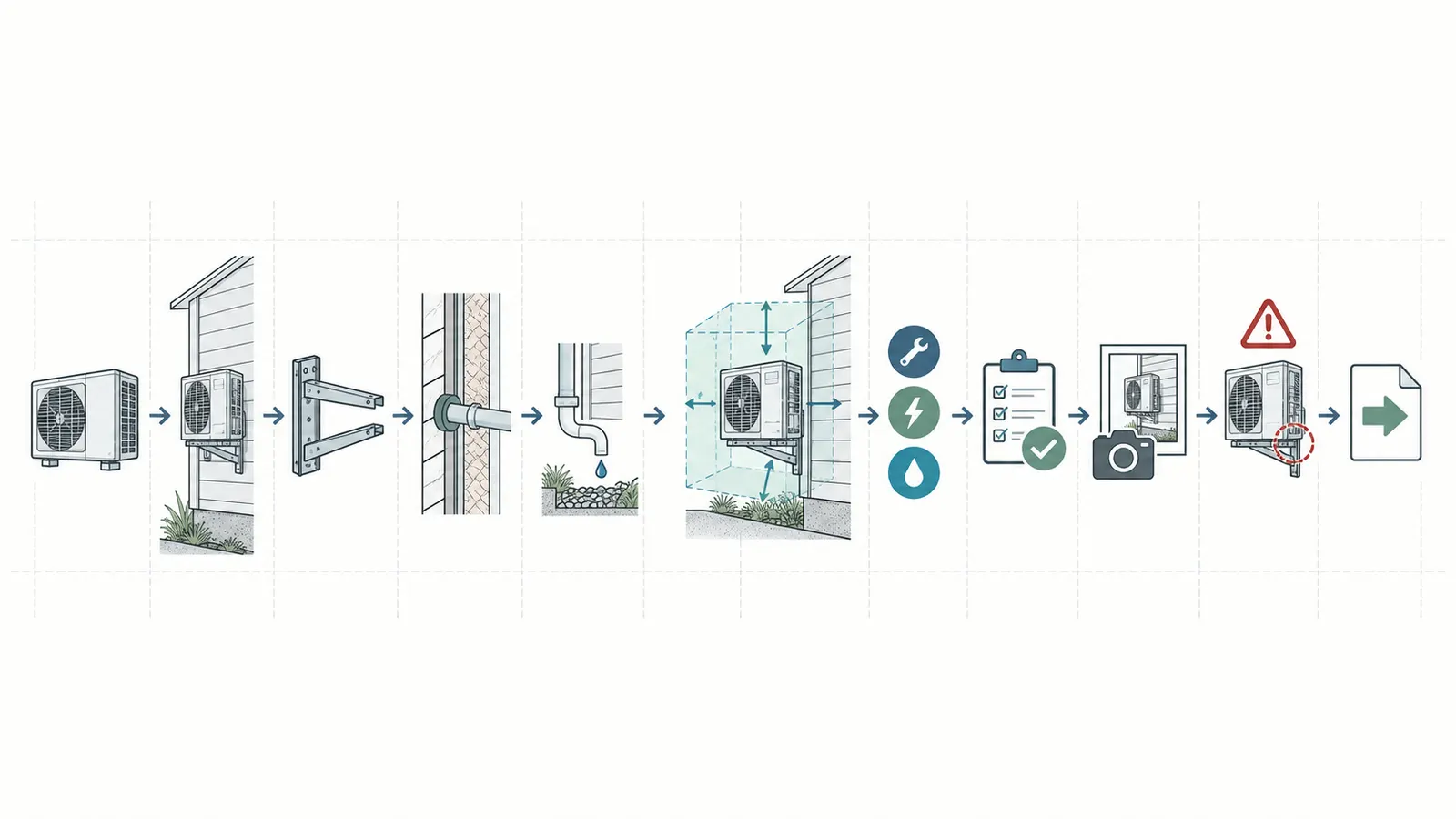
Before cladding, give every exterior fixture or service unit one approved location and one accountable handoff. Confirm the current model, finished-wall dimensions, support and fasteners, flashing and drainage path, electrical or plumbing route, service clearance, responsible trade, inspection gate, and photo record. Release cladding only after unresolved rows are closed or formally documented by the builder and applicable authority.How to Plan Exterior Equipment Mounting Before Cladding
Before cladding, give every exterior fixture or service unit one approved location and one accountable handoff. Confirm the current model, finished-wall dimensions, support and fasteners, flashing and drainage path, electrical or plumbing route, service clearance, responsible trade, inspection gate, and photo record. Release cladding only after unresolved rows are closed or formally documented by the builder and applicable authority.
The decision is not simply “where should the condenser go?” It is whether the wall, its weather-control layers, the equipment and the future service visit can coexist. A location that works on a floor plan can fail when a rainscreen, thick siding, trim, utility route, access panel, ladder position or replacement path is added. A sealed penetration can still have the wrong support, a blocked drain, insufficient airflow or no way to remove the unit later.
This guide is for a homeowner managing a U.S. new single-family build through a builder and licensed trades. It is a coordination and release process, not structural engineering, electrical design, a permit interpretation or remote approval of an installation. Your actual authority having jurisdiction (AHJ)—the city, county, state, tribal or other agency that administers the applicable permits—and the current manual for the selected product control the project-specific result.
1. Decide what must be frozen before the wall is covered #
Freeze the interface—not only the visible location—before cladding starts: the item, model, support, finished-wall reference, penetration, drainage route, service envelope, responsible trade, inspection gate and record must all be identified or deliberately deferred by the builder in writing.
The wall is about to change from an inspectable assembly into a finished surface. Once siding, stucco, masonry veneer, panels or another cladding hides the WRB, sheathing and blocking, the cost of correcting a missed support or damaged flashing rises sharply. The pre-cladding decision gate exists to prevent an attractive exterior from concealing an unresolved dependency.
What “frozen” means
An item is frozen when a person who did not attend the coordination meeting can use the record to answer all of these questions without guessing:
- What exact item is planned? Use a manufacturer, product family, model or utility-provided equipment requirement. “Heat pump” or “light” is not enough when the dimensions, weight, wiring, drain or service opening depends on the model.
- Where is it located? Identify elevation, wall grid or room reference, horizontal and vertical dimensions, and the datum used for those dimensions.
- Which wall face is the reference? Say whether a measurement is from framing, sheathing, WRB, furring or finished cladding. “Six inches from the wall” is ambiguous if the wall will gain two inches of furring and cladding.
- What carries the load? Record whether the item sits on a slab, curb, pad, post, bracket, mounting block or other support, and who confirms the support detail. Do not infer that cladding, trim or housewrap is a structural attachment surface.
- How does water leave? Identify the penetration sleeve or box, flashing or compatible penetration accessory, sealant or tape specified by the wall and product systems, and the exterior drainage destination. The drawing must show a path, not only a sealant note.
- How much space is required? Record the manufacturer’s model-specific clearances, required access for service and replacement, airflow or exhaust needs, door and panel swing, and any AHJ or utility requirement that applies at the actual address.
- Who does the next action? Name the builder or trade, not just “GC” or “mechanical.” A row without an owner is an unresolved row.
- What proves completion? Plan detail, approved submittal, photo, inspection record, pressure or functional test record where applicable, or written acceptance by the responsible professional should be named before work begins.
The word “frozen” does not mean no change is ever permitted. It means a change has a controlled path. If the owner later chooses thicker siding, a different condenser, a larger light, a different utility meter or a new exhaust hood, the row reopens. The builder then rechecks projection, support, drainage, clearances, routes and inspection timing before another trade closes the wall.
The release question
Ask the builder to answer this sentence for every item: “If cladding began tomorrow, what exactly would be hidden, who verified it, and what would we do if the model changed?” If the answer is “the siding crew will figure it out,” the interface is not ready. If the answer is “the electrician knows,” ask whether the electrician also owns the WRB flashing and cladding trim. A trade can own its installation without owning every adjacent layer.
The release question should be asked at the coordination meeting, at the wall inspection or pre-cover review if the project has one, and again immediately before cladding. The repetition is useful because installed conditions change. A new window, revised roof edge, moved downspout or added exterior outlet can invalidate an earlier location even when the equipment itself is unchanged.
Originality brief: why this worksheet is the missing decision
Current answers are fragmented: building-science sources explain drainage planes and flashing, OSHA explains employer fall-protection boundaries, local authorities publish their own inspection processes, and manufacturer manuals specify one product’s installation dimensions. They rarely give a homeowner a cross-trade release path that connects all four.
The missing decision is whether each exterior interface is ready to be hidden—not merely whether a penetration has been sealed. Brictale’s contribution is the Exterior service-interface register. It can be checked by tracing a row from the approved plan location to the current model manual, support detail, drainage detail, responsible trade, AHJ or utility gate, photo and next handoff. If one of those links is absent, the row is not complete.
Method: For each item, record the approved location and finished-wall reference, copy the current manufacturer inputs, add the wall and cladding build-up, calculate the required projection and service envelope, then obtain trade and AHJ confirmation before cladding covers the interface.
Limitations: This is an illustrative coordination worksheet, not structural engineering, an installation manual, a permit, an inspection result, or a substitute for the actual jurisdiction and current product instructions. Model, cladding, site, climate, and authority requirements can change the result.
The register is an organizing method, not an official form. Its value is that it makes the handoff inspectable. A homeowner can bring the rows to the builder, architect, mechanical contractor, electrician, plumber, cladding installer, utility and AHJ as appropriate, while each professional remains responsible for the work within that professional’s scope.
If the unresolved decision is the overall wall package, use the related exterior wall assembly planning guide alongside this register. That guide helps resolve the wall-system context; this guide keeps the equipment, support, access, inspection and cladding handoffs in the same row.
2. Build one exterior service-interface register #
Create one register with a separate row for every item that touches, penetrates, drains onto, sits near or needs service access from the exterior wall; do not group all “exterior utilities” into one row.
The assigned inventory should include at least a meter base, service disconnect, heat-pump or condenser unit, hose bib, light, receptacle, exhaust outlet and any communications or security equipment. Add gas regulators, generator connections, solar equipment, exterior cleanouts, irrigation controls, EV equipment, cameras, doorbell transformers, radon exhausts, vents, awnings and future conduits if they are part of the approved plan or likely to be added before completion. The register is most useful when it captures small items that otherwise get installed from a field mark.
Inputs to collect before the meeting
The homeowner can assemble the information without performing hazardous work. Ask for the latest architectural elevations, wall sections, cladding specification, window and door schedule, reflected ceiling or electrical plan where it affects exterior items, mechanical equipment schedule, plumbing fixture schedule, utility correspondence, landscape or hardscape plan, and any local inspection checklist already issued for the permit.
For each selected product, save the current U.S. installation manual or technical sheet with its revision or publication identifier. Record dimensions in inches, weight in pounds, electrical or fuel requirements only as stated by the product documents, drain connection information, prohibited locations, service openings and clearance diagrams. A screenshot without the model and revision is weak evidence because a later product revision can look similar while changing the interface.
For each wall, collect the build-up in the direction from structure to outside: structural sheathing or substrate, WRB, insulation or rainscreen, furring, cladding, trim, cap or mounting block. Some assemblies have more layers, and a designer or cladding professional must resolve the actual detail. The homeowner’s job is to make the layers visible in the conversation, not to choose a fastener or invent a structural detail.
Register template
Copy this table into the project decision log or use it as the agenda for a coordination meeting. “Open” is a valid status; silently assuming a value is not.
| Item and location | Model, dimensions and weight | Support type | Wall/cladding position | Penetration and flashing detail | Drainage path | Clearances (in) | Access owner | Responsible trade | Permit/inspection gate | Photos | Unresolved issue | Next handoff |
|---|---|---|---|---|---|---|---|---|---|---|---|---|
| Meter base, east elevation | Utility-approved model/standard; dimensions and weight: ___ | Utility-approved enclosure support/blocking | Finished cladding face and utility datum: ___ | Utility/electrical box; upper/lower flashing and trim detail: ___ | Exterior drainage destination: ___ | Working/access space: ___ in; directions: ___ | Utility and licensed electrician | Builder coordinates; electrician and utility decide within scope | Actual utility/AHJ gate: ___ | Wide elevation, support and pre-cover interface, row ID/date | Open: utility model and working-space dimensions pending | Utility/electrician release to cladding lead |
| Service disconnect, east elevation | Exact enclosure, dimensions and weight: ___ | Electrical box or approved mounting block | Face and door swing relative to finished cladding: ___ | Raceway/box penetration, flashing and seal detail: ___ | Drainage at box/trim: ___ | Working area: ___ in; panel swing: ___ | Licensed electrician/AHJ | Licensed electrician | Electrical gate defined by actual AHJ: ___ | Support, penetration and final label photos | Open: confirm AHJ working-space requirement | Electrician release to cladding |
| Heat pump/condenser, north pad | Exact model, dimensions, weight and manual revision: ___ | Slab, pad or bracket; qualified anchorage detail | Finished wall/cladding face, pad elevation and line-set reference: ___ | Line-set sleeve/cover; flashing and cladding trim detail: ___ | Model drain joint/hose and destination: ___ | Manual envelope: left ___, right ___, front ___, top ___ in; replacement path: ___ | Mechanical contractor/service technician | Mechanical contractor; builder coordinates support and wall detail | Mechanical submittal and applicable AHJ gate: ___ | Model label, support, drain, clearance and pre-cover photos | Open: verify selected model and cold-weather drain treatment | Builder handoff to startup/commissioning |
| Hose bib, side wall | Fixture/assembly model, dimensions and weight: ___ | Blocking or approved box | Finished face and handle projection: ___ | Pipe/sleeve, flashing and trim detail: ___ | Drain/freeze strategy and discharge destination: ___ | Handle/hose clearance: ___ in | Licensed plumber | Licensed plumber | Plumbing inspection or local gate: ___ | Blocking, pipe route and pre-cover photos | Open: site-specific freeze and discharge review | Plumber release to cladding installer |
| Exterior light, porch | Fixture model, dimensions and weight: ___ | Exterior electrical box/block and approved mounting | Finished cladding face, base and fixture projection: ___ | Box flange/gasket and WRB/flashing transition: ___ | Drip/trim drainage path: ___ | Removal/service clearance: ___ in | Licensed electrician | Electrician; cladding installer coordinates trim | Electrical gate at actual AHJ: ___ | Box/block before cover and final fixture photos | Open: confirm trim depth after cladding submittal | Electrician and cladding lead review |
| Exterior receptacle, deck | Device, box, cover, dimensions and weight: ___ | Exterior-rated box/block | Finished face and deck/rail reference: ___ | Box extension/conduit entry, gasket and flashing detail: ___ | Drainage from box/trim: ___ | Use/service zone: ___ in; furniture/rail conflict: ___ | Licensed electrician | Licensed electrician | Actual AHJ electrical gate: ___ | Box, conduit and finished device photos | Open: deck railing and furniture layout not frozen | Electrician release to cladding |
| Exhaust outlet, bath/laundry/kitchen | Fan/appliance model, duct size, dimensions and weight: ___ | Duct/hood support and termination backing | Finished cladding face and termination projection: ___ | Sleeve/duct, hood flange, flashing and seal detail: ___ | Duct slope/condensate destination: ___ | Opening/obstruction clearances: ___ in per manual/AHJ | Mechanical contractor | Mechanical contractor or HVAC/plumbing trade by scope | Mechanical/permit gate confirmed with actual AHJ: ___ | Duct, flashing and termination photos | Open: appliance manual and opening-clearance check | Trade release to cladding |
| Communications/security device | Provider/product model, dimensions and weight: ___ | Removable base/block or conduit support | Finished cladding face and service position: ___ | Low-voltage entry, drip detail and removable base | Water exit below entry: ___ | Service/replacement zone: ___ in | Low-voltage trade/provider | Low-voltage trade; builder coordinates | Provider/AHJ requirement if any: ___ | As-built entry and final device photos | Open: provider conduit and future replacement path pending | Builder handoff to owner documentation |
The table is intentionally broader than an inspection checklist. An inspector may not verify every future service concern, and a photograph may not prove a concealed detail. The register is for coordinating the people who know different parts of the wall. Keep the source document or approved detail beside the row, not only a note saying “per plan.”
Minimum row status values
Use a small controlled vocabulary so a green mark does not hide a gap:
- Draft: the item is expected but model, location or owner is incomplete.
- Coordinating: the current proposal is being checked against the wall, routes, access and adjacent work.
- Released for rough-in: the responsible professional has the information needed to place support, sleeve, box, line set or piping, but the wall is not yet released for cladding.
- Ready for cover: the interface is installed, inspected or otherwise verified to the extent required by the actual project, and the record package is complete.
- Hold—change: a model, cladding, location, route or site condition changed. The row cannot return to ready without a recheck.
- Closed: final installation and records are complete, with future owner information stored.
Do not use “complete” when only one trade has finished. For example, an electrician can finish a box while the cladding installer still lacks a flashing or trim detail. The row remains coordinating until the adjacent interfaces are accounted for.
3. Set every location from the finished wall, not the framing sketch #
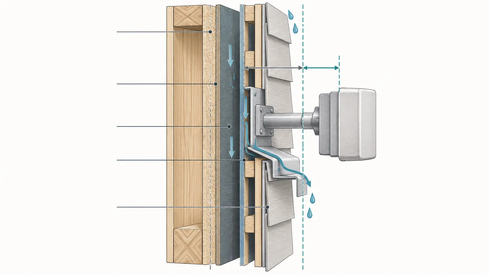
Dimension each exterior item from a named datum and show the complete finished-wall build-up, because the visible cladding face and the structural support face are different planes.
A plan location usually answers “which part of the elevation?” It does not necessarily answer “where is the equipment’s back, face, drain, conduit or service door after every exterior layer is installed?” Give the drawing or field mark a horizontal datum, a vertical datum, an elevation or grid reference, and a reference plane. A useful note might say: “centerline 18 inches south of window jamb, 42 inches above finished grade, dimensions to finished cladding face; support detail references sheathing and framing.” The exact numbers are project inputs, not universal recommendations.
Make the wall stack explicit
Measure or obtain the nominal thickness of each layer that affects the interface. Use inches consistently and distinguish nominal from installed dimensions. A simple worksheet field set is:
| Input | Symbol | Illustrative value | Why it matters |
|---|---|---|---|
| Rainscreen/furring thickness | (t_r) | 0.75 in | Moves the finished face away from sheathing and affects fastener reach |
| Cladding thickness | (t_c) | 1.00 in | Changes the mounting plane and trim depth |
| Cap, trim or mounting-block allowance | (t_a) | 0.50 in | May place the equipment base proud of the cladding |
| Required equipment-to-obstruction space | (C_m) | 24.00 in | Must come from the current model manual or applicable authority, not this example |
| Planned equipment-to-obstruction space | (C_p) | 24.00 in | The field layout must preserve this after the wall is finished |
For coordination, calculate the exterior build-up affecting the mounting plane as:
(P_wall = t_r + t_c + t_a)
In this illustrative example:
(P_wall = 0.75 + 1.00 + 0.50 = 2.25) inches
That 2.25 inches is not a structural capacity, a code minimum or a universal bracket dimension. It is a coordination quantity showing how far the relevant face moves from the sheathing reference. The qualified designer or trade still selects the support, fastener, blocking and flashing system for the actual substrate and load.
Draw the service envelope as a volume
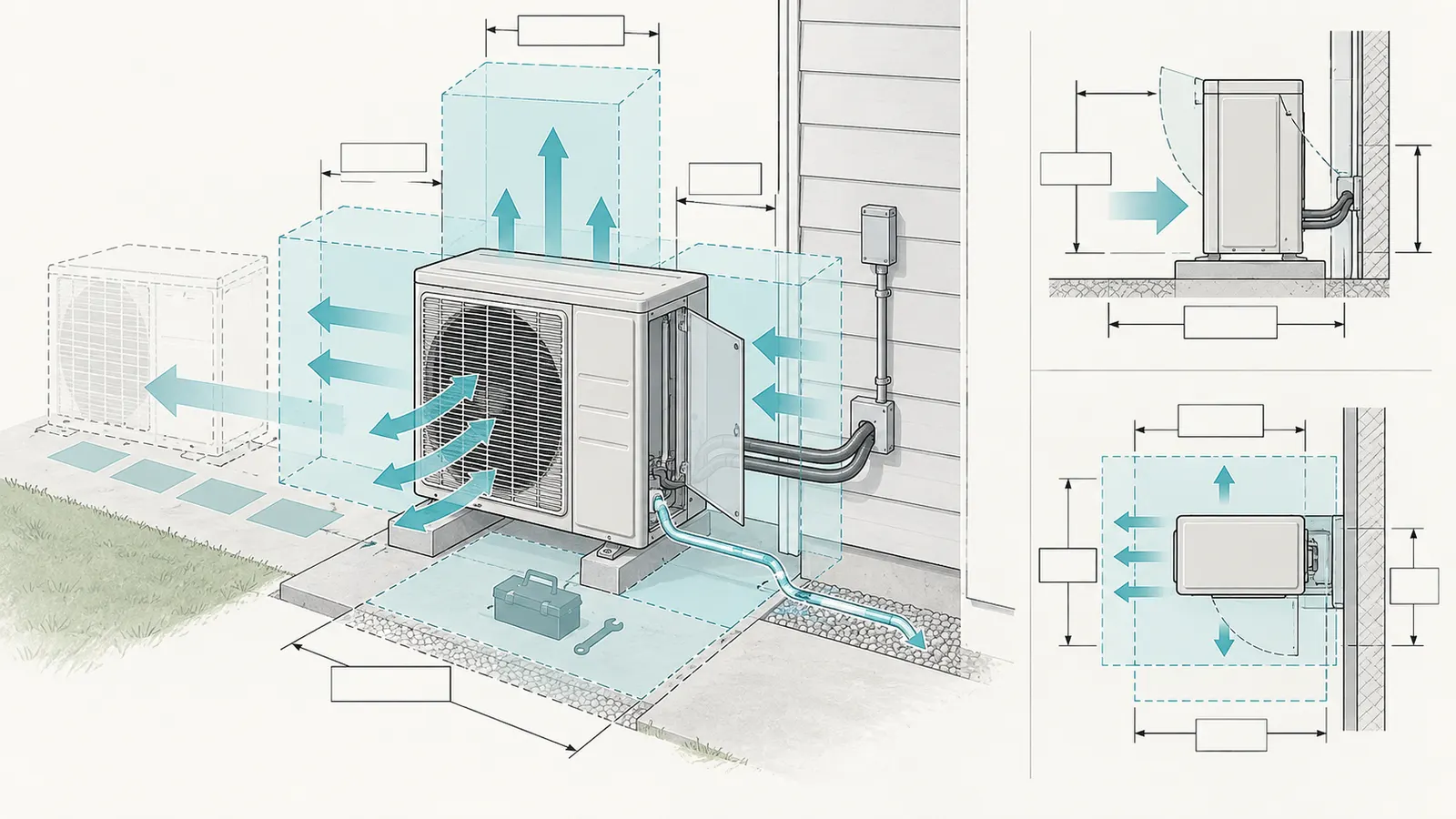
Clearance is not one line on the elevation. It is a volume around the item. Show the item’s width, height and depth; manufacturer obstruction clearances; service panel swing; tool space; removal path; drain path; conduit bend or line-set route; and nearby openings, roofs, decks, fences, plants and future finishes.
For a heat pump, the volume may need both airflow space and a technician’s access zone. For a meter or disconnect, the volume includes a working area that the electrician and authority must confirm. For a light, the important envelope may be fixture removal and ladder access rather than airflow. For an exhaust outlet, it includes the termination’s relationship to windows, doors and other openings as established by the current appliance instructions and local requirements.
Do not copy the largest number on a random internet page into every row. The manufacturer may provide several dimensions for different sides of a unit, and a local utility or AHJ may impose an additional requirement. Record the source and the direction for each clearance: left, right, front, top, rear, above grade, below an opening, or access zone.
Keep three locations separate
Record these as separate fields even when they appear close together:
- The penetration location: where pipe, wire, duct, sleeve or line set crosses the wall.
- The support location: where the box, bracket, block, pad or anchorage transfers load or holds the item.
- The service location: the space a person, tool, replacement part or removable panel needs.
They can conflict. A line-set sleeve may be near the unit but too high for the drain to fall continuously. A support block may be perfectly centered but put the unit’s service panel behind a downspout. A receptacle can be reachable today but blocked after the deck railing is installed. Ask the trade to mark all three on the elevation and the wall section.
Protect the next decision
If the final cladding is not selected, do not release a precise bracket location as though the wall were final. Record an allowed range and the decision date. The unresolved input should be visible: “cladding thickness pending; support projection and trim to be rechecked after approved submittal.” The safe next decision is to select or approve the wall assembly, then run the row again. A vague allowance is not the same as a reserved interface.
4. Approve support, flashing, drainage and model-specific clearance together #
Release an exterior item only when its support, water path, product clearances and future service access work as one detail; a sealed hole alone is not a complete interface.
Building Science Education describes a continuous drainage plane behind exterior wall cladding and says it should lap over flashing around wall penetrations so moisture can drain down and away from the wall. The U.S. Department of Energy’s drainage-plane guidance is general enclosure guidance, not a project-specific code approval. For a broader companion on documenting the wall’s cladding, drying and vapor-control package, see the new-home cladding, drying and vapor-control brief. This is the core reason the wall section matters: the item’s support and penetration must meet the wall’s water-control strategy, not merely receive a bead of caulk at the outside face.
Support is a separate decision from weather sealing
An exterior item can be light, but the connection still experiences its own loads: the item’s weight, wind, vibration, maintenance handling, conduit or pipe forces, and sometimes ice, snow or impact depending on location and product. A homeowner should not calculate structural capacity from this article. Ask the builder, designer, engineer or qualified trade who owns the support decision and what substrate the fasteners enter.
For a wall-mounted light, the support may be an electrical box and a manufacturer-approved mounting method. For a hose bib, it may be a block or box that keeps the fixture stable while a hose is connected. For a condenser, the support might be a slab or bracket selected for the actual unit and site. For a meter base, the utility or electrical professional may control the equipment and mounting requirements. The cladding installer should not be expected to improvise load transfer using the siding alone.
Document the support reference, fastener or anchorage specification if the responsible professional supplies it, blocking location, access to install it, and whether the cladding will cover the support edge. If the support is installed before the WRB, the builder must coordinate how the WRB and flashing pass around it. If the support is installed after the WRB, the penetration detail must preserve the drainage path. The correct sequence depends on the wall system and approved detail.
Treat a penetration as a layered transition
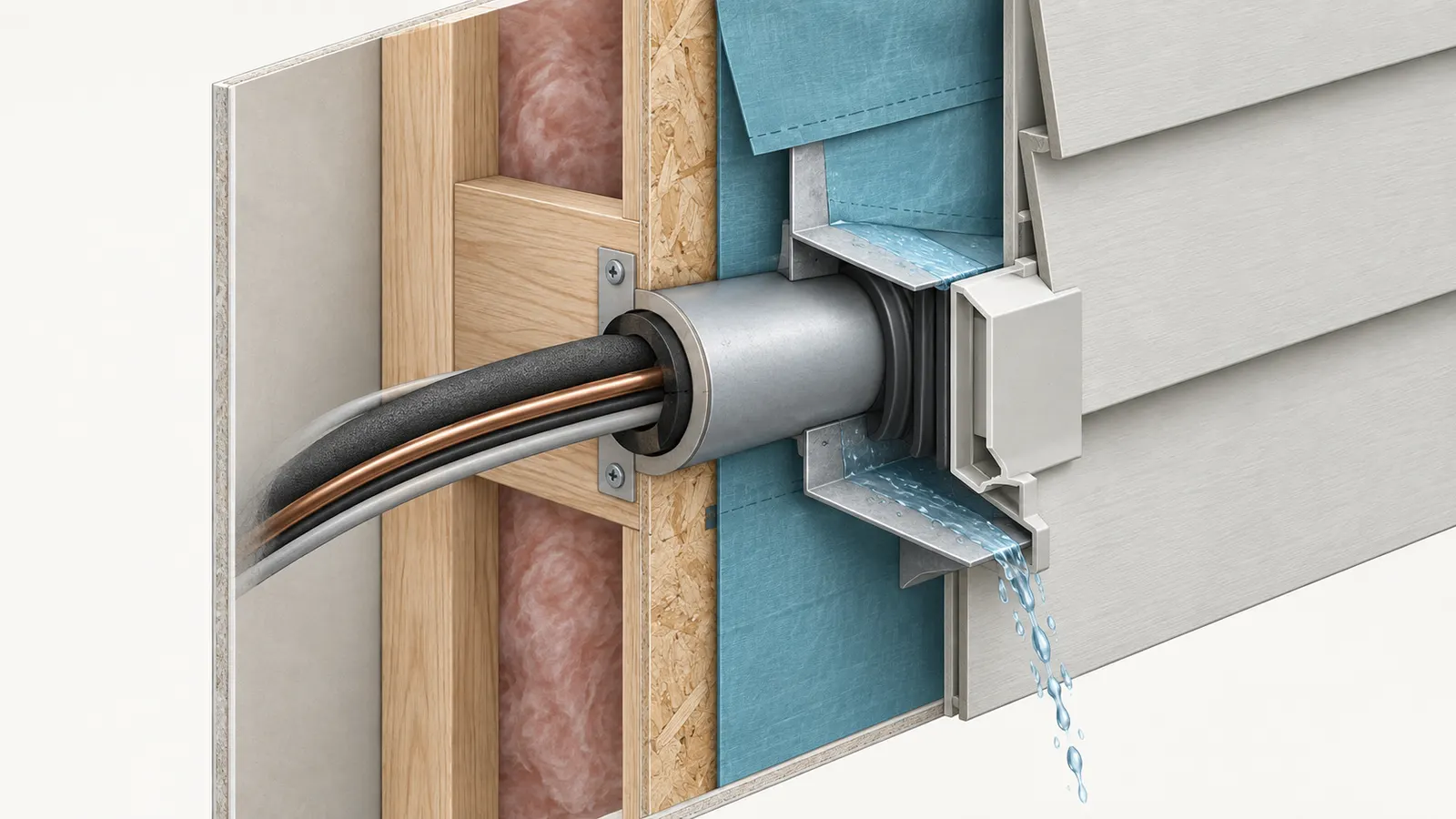
The source plan for this assignment lists spigots, exhaust outlets, HVAC line sets and wiring for outdoor lights and receptacles as common wall penetrations. DOE Building Science Education identifies those examples and says holes through the wall should be thoroughly sealed or gasketed. The homeowner should read “seal” as one part of a transition: location, sleeve or box, flashing, WRB integration, cladding trim, sealant compatibility and drainage all have to be addressed.
The exact product may be a flanged penetration, a box with an integrated flange, a membrane detail, a sleeve, a duct hood or another approved accessory. Do not mix a random tape, membrane, sealant and cladding accessory simply because each product is labeled waterproof. The builder or enclosure professional should confirm compatibility and sequence. Ask which layer is the drainage plane, where the upper layer laps over the flashing, and where water exits after it reaches the penetration.
BSC Information Sheet 303 on common flashing details states the fundamental direction as out over the cladding or drainage plane and warns against openings that send water back into the wall. It also illustrates that special flashing details can be required for attachments and penetrations. This is a useful review question, not permission to fabricate sheet metal on site.
Give gravity a visible path
A drain should be assigned a destination before the unit is placed. “It drains outside” is incomplete if the outlet discharges onto a walkway, foundation, lower roof, deck, cladding joint or another component that cannot tolerate repeated water. A line may need continuous slope, a trap, insulation, a termination fitting, a freeze strategy or a condensate disposal method depending on the product and jurisdiction. Those decisions belong to the relevant licensed professional.
The Gree Livo Gen4 manual provides a useful model-specific example of why this belongs in the register. It instructs the installer to select the location according to the house structure, fix the outdoor-unit support, ensure the support can withstand at least four times the unit weight, elevate the unit for the drain joint, and keep the drain hose sloping downward without upward or fluctuating sections. Those instructions are in the Gree Livo Gen4 installation manual. They apply to that manual’s covered model family and conditions; they are not a general rule for every condenser or heat pump.
This example changes the homeowner’s questions. Instead of asking only “is the unit on a pad?” ask “where is the pad relative to finished grade, what happens to water in this climate, is the drain joint part of this model, what supports the unit, and can a technician reach the connections?” A model manual may require a particular elevation or prohibit a drain accessory in a severe-cold area. The current manual and local professional control.
Read clearance diagrams as directions, not just numbers
The Gree Livo Gen4 model family’s outdoor-unit clearance diagram in Installation Manual A (CAT NO. GREE_4LIV_AO_INSTALL_03012023) shows minimum obstruction dimensions of 6 inches, 12 inches and 24 inches on printed page 8 (PDF page 12). The manufacturer diagram should be read in its original context: the exact side, top, front or airflow meaning must be matched to the current model’s figure. Those three numbers must not be turned into a universal “six inches everywhere” rule or pasted onto another brand.
In the register, write a clearance entry such as “left side: ___ in minimum per manual page ___; planned ___ in; front service envelope: ___ in; top obstruction: ___ in; replacement path: ___.” If a professional says the installation needs more room for service than the manual minimum, record the professional’s requirement and owner. If the site cannot provide the minimum, the next decision is relocation or a different approved product—not a smaller gap chosen for appearance.
Check conflicts before approving the aesthetic layout
Run the clearance volume against:
- windows, doors and their operation;
- roof eaves, valleys, gutters and downspouts;
- decks, stairs, railings and future handrails;
- walkways, driveways, snow-storage areas and landscape beds;
- utility routes and meter access;
- exhaust outlets, intakes and combustion or refrigeration equipment;
- property lines and any local or utility restrictions;
- cladding joints, trim, control joints, weeps or drainage openings;
- the path needed to remove the largest serviceable component.
The last check is often missed. A unit can have adequate operating clearance while its replacement path is impossible because a railing or masonry return was built afterward. Ask what dimensioned opening or removable panel would let a technician replace the unit without dismantling unrelated finished work. That may be a practical owner requirement rather than a code requirement, so label it accordingly.
5. Assign trades, permits and the inspection handoff by jurisdiction #
The builder should assign each interface to a named trade and confirm the actual permit and inspection path with the AHJ, utility or other authority at the home’s address; there is no single national pre-cladding inspection sequence that homeowners can assume.
The owner’s role is to make responsibility visible and ask for the right handoff. The electrician owns the electrical installation within the electrician’s scope, the plumber owns plumbing work within the plumber’s scope, the HVAC professional owns equipment installation and commissioning within that scope, and the cladding or enclosure professional owns the finish and its interface as assigned by the contract. The builder coordinates the sequence unless the contract says otherwise. A designer or engineer may own details that require design judgment. The utility may control a meter or service connection. The AHJ decides what it will inspect and when.
Use Austin only as an example of why location matters
For a concrete local example, the City of Austin, Texas says its Building Inspections function performs construction-related inspections for residential and commercial buildings within Austin city limits, while the same inspections page identifies electrical and plumbing services in the extraterritorial jurisdiction separately. Austin Development Services’ inspections page therefore demonstrates a jurisdictional boundary; it does not tell a homeowner in another city, county or state which office will inspect a wall penetration.
Austin’s building-inspection page also tells applicants to keep the latest city-approved plans accessible, upload required documentation, and complete prerequisite inspections before requesting a temporary certificate of occupancy or final building inspection. Those instructions are specific to the City of Austin, Texas. They suggest a good coordination habit for any project—keep the current plan and records available—but they are not a nationwide rule. Ask the actual AHJ which inspection must occur before the wall is concealed and which documentation it wants.
The same Austin page says supporting documentation such as surveys, photos and engineering reports may be required for an inspection and can help inspectors verify compliance and prevent processing delays. Austin’s documentation guidance is again a local example. A photo is a record of what was visible; it does not prove that concealed work complies, and it does not replace an inspection when the AHJ requires one. For a separate record-focused companion, use the new-home inspection-records and trade-handoffs guide.
Build a responsibility matrix
Use a separate owner for each action, even if one company performs multiple scopes. The homeowner can ask the builder to fill this matrix before rough-in:
| Decision or action | Primary responsible party | Homeowner verification question | Handoff |
|---|---|---|---|
| Select exact product/model | Builder with owner and relevant trade | Is the saved manual for the exact model and current revision? | Submittal to design, trades and inspector as required |
| Confirm wall build-up | Builder, designer or cladding professional | Are all layers and finished-face dimensions on the section? | Dimensioned interface detail |
| Confirm load/support path | Qualified designer, engineer or installing trade as applicable | What substrate carries the item, and who accepted it? | Support/blocking detail before WRB or cladding covers it |
| Detail penetration and drainage | Builder with enclosure/cladding and installing trade | Where does water go at the top, sides and bottom? | Approved wall/penetration detail |
| Confirm electrical/plumbing/mechanical requirements | Licensed trade and actual AHJ/utility as applicable | Which permit or inspection gate applies at this address? | Rough-in or pre-cover inspection request |
| Install and photograph concealed interface | Builder assigns trade or site supervisor | Is the photo tied to grid/elevation and row ID? | Record package before cladding |
| Install cladding trim and finish | Cladding installer with builder | Does the finish preserve clearances, access and drainage? | Final row review |
| Commission and document equipment | Equipment trade | Are startup settings, model/serial and service information stored? | Owner handover |
“Homeowner verification” means reviewing records and asking questions; it does not mean the homeowner signs off electrical, structural or mechanical work. If the builder asks the owner to approve a detail that requires engineering or trade judgment, ask for the responsible professional’s review instead.
Questions for the actual AHJ
Give the permit office a concise, address-specific question rather than asking the internet for a universal answer:
- Which authority issues the building, electrical, plumbing and mechanical approvals for this parcel?
- Does the project require a pre-cover or framing inspection before exterior cladding conceals the WRB, blocking, boxes, sleeves or flashing?
- Are equipment supports, exterior outlets, disconnects, meter bases, exhaust terminations or condensate routes separately inspected?
- Must approved plans, product submittals, engineering details or photographs be uploaded or available on site?
- Which prerequisite inspections must be complete before a final inspection or certificate request?
- Does the utility—not the building department—control the meter location, access or service release?
- Does a state OSHA-approved plan govern the employer’s fall-protection program instead of federal OSHA enforcement?
Write the name of the authority, the contact date, the answer, the permit number and the person who received it. “The contractor said it is fine” is not a jurisdiction record. The guide excludes inspection-outcome promises because remote assessment cannot see the site, and because the actual authority’s current direction can change.
6. Sequence rough-in, weather control, cladding and commissioning #
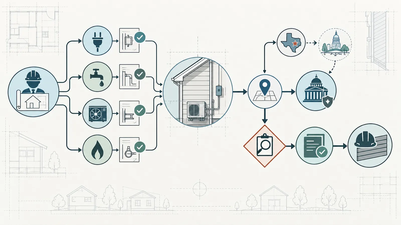
Sequence the work so each trade can verify the layer it installs and can hand the next trade a readable record before that layer is hidden.
The exact order depends on the wall system, product and permit schedule, but the decision logic is stable. Start with the approved interface, then place structural support or substrate provisions, establish the drainage-plane transition, install rough-in routes and penetrations, inspect or document the concealed work as required, install the cladding and trim, install or connect finish equipment, and verify operation and owner records. Do not treat “cladding day” as the first time all parties discover the final location.
Stage 1: approve the coordination set
The builder should circulate one current set containing elevations, wall sections, equipment schedule, clearances, support details, penetration details and register rows. Mark revisions. A drawing that shows the condenser but not the line-set sleeve, drain, support and clearance envelope is not a complete interface drawing.
At this stage, the homeowner decides what must be visible from the street, what noise or discharge direction matters for living areas, what future service access is acceptable, and which items should not share a crowded wall. The homeowner does not decide technical capacity alone. Ask the mechanical professional whether the selected location works for line length, airflow, service and commissioning; ask the electrician or utility about the service equipment; ask the cladding professional how the finish will terminate.
Stage 2: place support and route provisions
Install blocking, pads, curbs, brackets, sleeves, boxes, line-set paths, ducts, pipes and conduits according to the approved details and the responsible trade’s scope. Check the field location against the current elevation before the next layer covers it. Do not measure from an unverified chalk mark if a window or framing opening has moved.
At the end of the stage, update each row with the installed position, not the intended position. If a support moved by two inches to avoid a stud conflict, the service clearance and finish trim must be checked again. A field adjustment can be reasonable, but it is a change until the affected rows are re-released.
Stage 3: integrate the WRB and flashing
The drainage plane is a system, not a sticker around the visible hole. The U.S. Department of Energy’s Building Science Education guidance says a fully sealed continuous drainage plane should be behind wall cladding and that it should lap over flashing around wall penetrations. Use that drainage-plane principle when reviewing the approved detail, while following the actual WRB, flashing, penetration accessory and cladding manufacturer instructions.
Building Science Corporation’s residential water-management report notes that shingle lapping is especially important at changes in construction and that taping does not substitute for proper shingle lapping. It also explains that prolonged exposure can damage housewrap or building paper and calls for inspection and repair before cladding. The residential water-management report is older general guidance, so the builder must pair it with the current wall-system instructions and exposure limits for the selected products.
This is the moment for the enclosure or cladding lead to confirm the top, sides and bottom of each transition. The homeowner can observe whether the item has a named detail and whether the record photo shows the wall grid, but should not peel, cut, tape or rework the WRB. If the detail is damaged, stop the cover sequence and have the responsible professional specify repair.
Stage 4: complete the applicable inspection or record gate
Before cladding hides the interface, confirm the actual AHJ’s prerequisite and inspection requirements. If the AHJ does not inspect the concealed detail, the builder should still preserve the approved detail, product manual, row status and photo record. If a required inspection has not occurred, do not ask the cladding crew to make the issue disappear.
The Austin example shows why this gate belongs in the sequence: the city tells applicants to keep approved plans accessible, upload required documentation and complete prerequisite inspections before certain final requests. Austin Development Services’ process page supports that local workflow, but the homeowner must substitute the actual project authority.
Stage 5: install cladding and preserve the interface
The cladding installer follows the approved trim, clearance and drainage detail. The finish should not cover a service door, reduce a model clearance, block a drain, reverse a flashing lap or trap water against a penetration. The cladding installer should report a conflict instead of cutting around it without a record.
Exposure time matters before this stage. The DOE-hosted water-management report describes tears, elongated fastener holes and other damage from prolonged exposure. If the WRB has been exposed longer than the product allows, or if wind and handling damaged it, the builder should obtain the product-specific repair direction before finish work. “It will be covered” is not a repair method.
For cladding systems with a drainage gap, furring or a drainage mat, record how the service interface preserves that gap and where water exits. A block or trim piece can create a local dam if its lower edge has no drainage strategy. The correct detail varies by cladding; do not treat a generic mounting block as a universal solution.
Stage 6: install, connect and commission
Finish equipment only after the wall and support are ready. The equipment trade confirms the model, connection, drain, operating clearances, service access and startup requirements. The electrician, plumber or other trade completes its connection and applicable inspection. The builder collects model and serial information, manuals, warranty instructions, service contact and the final photo.
The Gree manual warns that installation, movement or maintenance of the air conditioner should be handled by the dealer or local service center and that refrigerant work should be handled by certified professionals. The manual’s safety boundary is model-specific but illustrates the broader rule: the homeowner can coordinate and document; qualified professionals perform refrigerant, electrical, structural and other hazardous installation work.
Falls and site safety are employer responsibilities
Exterior finishing can put workers near edges, openings, ladders, scaffolds and roofs. OSHA’s residential fall-protection guidance is intended to assist employers, is not itself a standard or regulation, and says employers remain responsible for applicable requirements and suitable work methods. Read the OSHA guidance in that employer-controlled scope. The homeowner should keep out of the work zone and should not direct a crew to work from a ladder, roof or scaffold to “just get one measurement.”
For covered residential construction work at 6 feet or more above a lower level, OSHA’s rule generally requires guardrails, safety nets or personal fall arrest systems, subject to the rule’s provisions and any permitted alternative. 29 CFR 1926.501(b)(13) is the federal reference for that boundary. State-plan jurisdiction, employer status, task and site conditions matter. This article does not create a site-specific fall-protection plan, and a homeowner should direct safety questions to the builder’s competent person or safety program.
7. Verify the interface before releasing cladding #
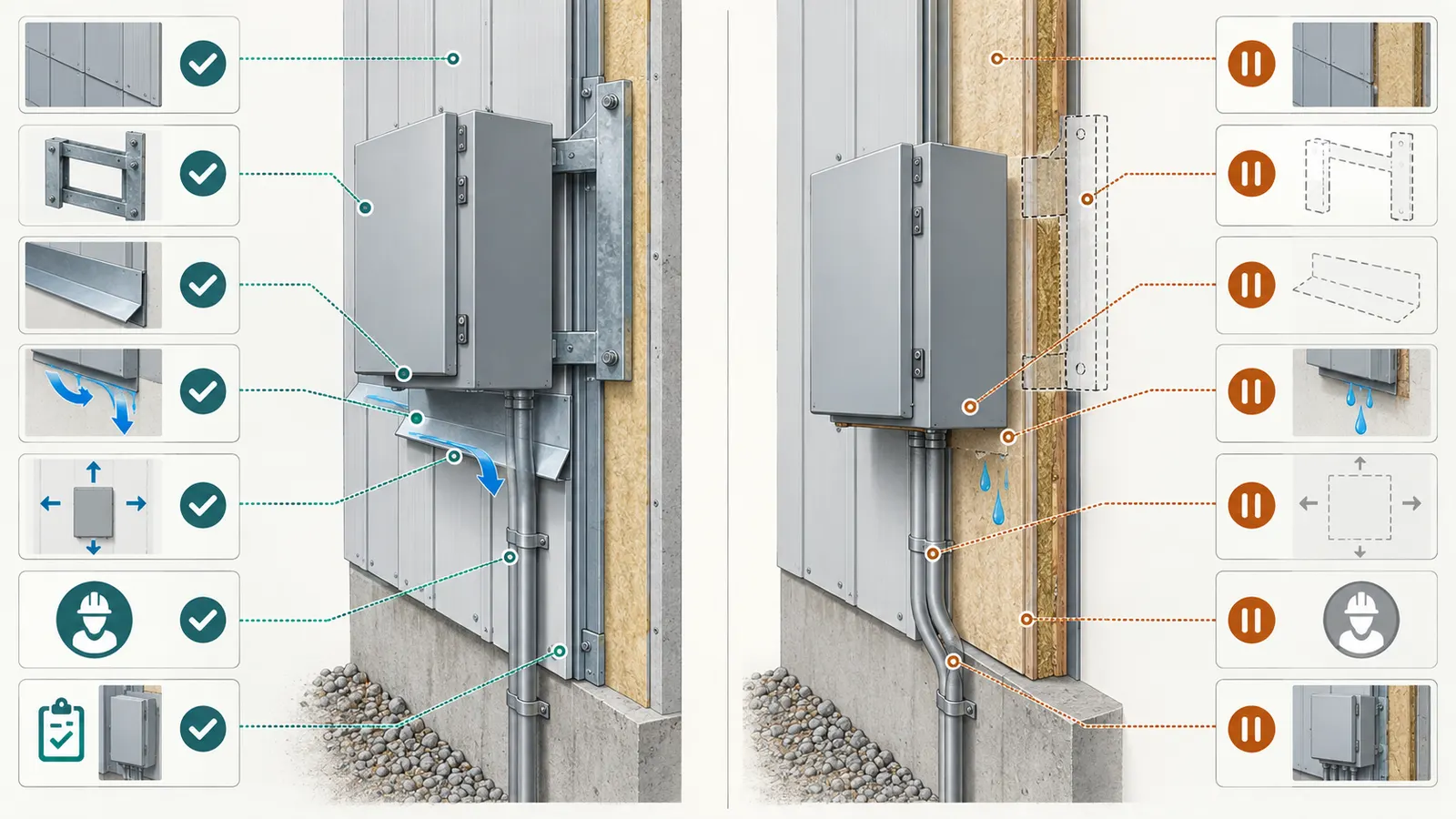
Use a row-by-row hold point before cladding: observe the installed condition, compare it to the current documents, verify the record, and obtain the responsible professional’s release before the next layer hides it.
The review should be calm and boring. The goal is not to catch a trade in a mistake; it is to make the next handoff unambiguous. Schedule enough time for the builder, relevant trade and cladding lead to walk the wall. Bring the register, latest elevations and sections, current product manuals, utility or AHJ notes and a camera or project-record system.
What the homeowner can observe safely
From the ground or an authorized safe area, the homeowner can compare:
- the item’s elevation and horizontal position with the register;
- visible support blocks, pads, brackets or boxes with the detail;
- the model label or delivery record with the approved model;
- whether the clearance volume is obviously crowded by windows, doors, roofs, rails or stored materials;
- whether a drain, duct, sleeve, conduit or line set has a named destination;
- whether the photo has a location reference and date;
- whether the current plans and approved revision are the ones being used;
- whether the row identifies the next person and next event.
The homeowner should not climb, remove cladding, open energized equipment, move a condenser, pull on a support, test a circuit, disturb refrigerant piping or enter an excavation or restricted work zone. A visual observation is useful evidence of location and recordkeeping, not a technical sign-off.
The four-part verification test
For each row, ask four different questions:
- Identity: Is this the item and model that the support and clearance decision was based on?
- Interface: Can the responsible trade point to the support, penetration, flashing and drainage detail?
- Envelope: Does the finished-wall position preserve the manufacturer, utility, AHJ and service requirements?
- Handoff: Is there a record and a named next owner before the next layer begins?
If any answer is “not yet,” set the row to Hold—change or Coordinating. Do not use the photo as a substitute for the missing support decision. Do not use a passed rough inspection, if one occurred, as proof that a later cladding change preserved every clearance. Verification is time-specific.
Photo record that can be found later
Take or request photos before the WRB, flashing, support, box or sleeve is concealed, as permitted by the builder and site rules. Use several views: a wide elevation showing location, a square-on view showing the interface, a close view of the support or flashing, and a view showing route and drainage. Place a tape measure or marked dimension only when the professional on site permits it and it does not create a hazard. Do not stage a measurement by reaching into an unsafe area.
Name files with the row ID, elevation and date. Example: HP-01-north-wall-wrb-2026-09-08.jpg. Store the photo with the current drawing revision and a note describing what is visible and what remains concealed. A photo should answer “where is this?” six years later, when a future owner or service contractor opens the project record.
The Austin, Texas example says photos may be among supporting documents that help inspectors verify compliance, but that local statement does not mean every AHJ accepts photos or that photographs replace an inspection. Use the City of Austin page only for that named local example. For any other location, ask the authority and follow the project’s permit process.
Release checklist
The builder can use this as a pre-cladding hold point. The homeowner can ask for the completed rows and the responsible person’s release.
- The latest architectural elevation and wall section identify the item and finished-wall datum.
- The exact product, model, dimensions, weight and manual revision are saved.
- The structural or equipment support owner is named and the support detail is approved by the responsible professional.
- The penetration, sleeve, box, duct, line set or pipe location matches the current plan.
- The WRB, flashing, cladding trim and drainage path have a coordinated detail.
- Model-specific operating, airflow, exhaust and service clearances are written with directions and units.
- The replacement or removable-panel path has been considered.
- The item does not conflict with openings, roof drainage, walkways, rails, landscaping or utility access.
- The actual AHJ, utility and permit/inspection gate are identified; local rules are labeled by jurisdiction.
- Required prerequisite inspections or professional reviews are complete, scheduled or explicitly not applicable.
- Concealed-work photos are tied to row ID, location, date and drawing revision.
- The unresolved issue field is empty, or the builder has documented a change-control decision and new next action.
- The cladding installer has the current detail and knows what must not be covered or reduced.
Only after the applicable boxes are satisfied should the row move to Ready for cover. “The crew will return later” belongs in the next-handoff field with a date and owner, not in a green status.
8. Reopen changed rows and hand the record to ownership #
Reopen a row whenever the model, wall thickness, location, support, route, cladding or authority requirement changes; then recheck the full interface before deciding whether cladding can proceed.
Change control is where most pre-cladding coordination systems fail. The visible item can look unchanged while a different wall assembly reduces clearances or changes the support reference. A substitute unit can fit the opening but require more airflow room, a different drain, a larger disconnect, a different sleeve or a stronger support. A revised landscape plan can block the service path. The register should make those changes normal and traceable rather than embarrassing exceptions.
Worked sensitivity check: what if the cladding gets thicker?
The following is a modeled illustrative example, not a site measurement and not a product approval. Suppose the register was released with:
- (t_r = 0.75) inches of furring;
- (t_c = 1.00) inch of cladding;
- (t_a = 0.50) inches for a trim or mounting-block allowance;
- planned mounting-plane shift (P_wall = 0.75 + 1.00 + 0.50 = 2.25) inches;
- a model-specific minimum obstruction clearance in the affected direction (C_m = 24.00) inches, using the Gree Livo Gen4 model family’s Installation Manual A, CAT NO. GREE_4LIV_AO_INSTALL_03012023, printed page 8 (PDF page 12), as the source for this illustrative row;
- planned clearance in that same direction (C_p = 24.00) inches after the original finish was installed.
Now the owner changes to cladding that is 0.75 inches thicker while the bracket and nearby obstruction remain fixed. The change is:
(Delta t_c = 1.75 - 1.00 = 0.75) inches
If the equipment and bracket do not move with the finish, the effective clearance at the affected direction is modeled as:
(C_new = C_p - Delta t_c = 24.00 - 0.75 = 23.25) inches
Compared with the illustrative Gree manual minimum in that direction:
(23.25 - 24.00 = -0.75) inches
The row is therefore a hold, not a release. The choices are to move the support or equipment, revise the bracket or mounting block through a qualified professional, change the cladding detail, select a different approved product or obtain a documented professional solution. The homeowner should not solve the deficit by trimming the cladding, moving a drain or accepting the smaller gap.
| Sensitivity input | Base case | Changed case | Register consequence |
|---|---|---|---|
| Furring (t_r) | 0.75 in | 0.75 in | No change |
| Cladding (t_c) | 1.00 in | 1.75 in | Recalculate finished-face relationship |
| Trim/adapter (t_a) | 0.50 in | 0.50 in | Confirm compatibility with new finish |
| Wall build-up (P_wall) | 2.25 in | 3.00 in | Mounting plane shifts 0.75 in |
| Planned obstruction clearance (C_p) | 24.00 in | 23.25 in if support stays fixed | Compare again to actual model minimum |
| Status | Ready for review | Hold—change | Builder reopens support, trim, drainage and clearance rows |
The formula is useful because it exposes the direction of the change. It is not a substitute for measuring the installed wall or for checking the full three-dimensional envelope. If the new cladding also changes furring, trim, drainage gap or the location of the obstruction, include every changed input. If the support is moved outward, check fastener embedment, water detailing and structural responsibility again; a clearance improvement can create a support or penetration problem.
Worked model-change check
If a condenser model changes, compare more than width and height. Record old and new:
- cabinet width, height and depth;
- unit weight and center-of-gravity or support points if supplied;
- required side, rear, front, top and service clearances;
- airflow direction and discharge;
- drain joint, drain hose or condensate behavior;
- line-set, duct, conduit or electrical connection locations;
- mounting-hole pattern or support interface;
- sound, exhaust, intake or safety restrictions stated by the manual;
- commissioning and qualified-installer requirements;
- availability of a future replacement path.
Then run the model-change row through the same four-part verification test. “Same brand” is not “same interface.” If the new model’s manual is not available, the correct status is Draft or Hold—change. Do not use a product photograph or salesperson’s verbal assurance as a substitute for the current installation document.
Common failure cases and safe next steps
The siding crew arrives before the model is selected. Stop the release of the affected interface and ask the builder whether temporary weather protection can preserve the wall while the submittal is resolved. If a temporary mark is needed, label it as non-final. The next decision is product selection or a written allowance that identifies who will recheck every dimension.
The support lands between studs or over an unknown substrate. Do not add random fasteners or assume the cladding will carry the load. Ask the responsible designer, engineer or qualified trade to approve the support and anchorage for the actual wall. The next handoff is an approved support detail and a location record.
A mounting block is flush with the wrong plane. If the block was sized from sheathing but the trim was sized from finished cladding, the item may sit recessed or project too far. Measure the actual wall stack, rework only under the builder’s and trade’s direction, and update the row. The next decision is a corrected block/trim detail, not extra sealant.
A penetration is sealed on the outside but has no upper flashing lap. A surface seal may not explain how water drains through the wall system. Pause the cover sequence and ask the enclosure or cladding professional to identify the approved drainage-plane transition. The next handoff is a documented repair or approved detail with a photo.
The drain discharges onto a walkway, deck or lower roof. Do not redirect it informally with a loose hose. Ask the mechanical or plumbing professional to confirm the product-specific drain and a suitable destination for the climate and site. The next handoff is a verified drain path and an updated finish detail.
The equipment meets the manual clearance but cannot be serviced. Treat service access as a project requirement and ask the installing trade to demonstrate the panel-removal and replacement path. Relocation, a removable panel or a different product may be needed. The next handoff is a revised plan that documents the access volume.
A light, receptacle or disconnect is placed where a future railing will go. Reopen both the electrical and architectural rows. The homeowner should not ask the electrician to move an energized installation casually. The next decision is the coordinated rail, furniture and service layout, followed by the applicable licensed-trade and AHJ review.
The WRB was left exposed and torn. Do not assume cladding hides the damage. The DOE-hosted residential water-management report explains that exposure and fastener damage can create discontinuities and calls for inspection and repair before cladding. Use that source as general water-management context, then follow the actual WRB product and builder’s repair method. The next handoff is a repaired, documented wall ready for review.
The homeowner is asked to climb up for a photo. Decline and ask the builder’s competent person to provide a safe record. OSHA’s rule and guidance place fall-protection duties on employers for covered work; the OSHA standard and OSHA residential guidance do not authorize a homeowner to improvise elevated access. The next handoff is a photo taken under the site safety program.
The builder says the inspection passed, so all details are closed. Ask which inspection, which scope and which date. A local inspection is not a universal approval of every future service clearance, and a later cladding or model change reopens the row. The next decision is to reconcile the inspection record with the current register and plans.
Handover record for the future owner
At completion, turn the register into an owner-facing record. Keep the final elevation and wall details, model and serial numbers, manuals, warranty contacts, service clearances, drain destinations, shutoff or disconnect locations, photographs, permit and inspection records that the builder is required or willing to provide, and the date of the last coordination review.
For each item, record what the owner may safely observe and what requires a professional. For example, the owner may keep the condenser clear of stored items and notice standing water, but should not open refrigerant connections or move the unit. The owner may keep a hose bib area accessible, but should not alter a concealed pipe or wall seal without the plumber’s direction. The owner may check that a vent termination is not blocked by new landscaping, but should not modify the duct termination without the responsible trade.
Add a maintenance consequence to the row: “keep clearance zone open,” “inspect visible seal and trim at routine exterior review,” “keep drain outlet unobstructed,” or “use licensed service provider for equipment.” These are ownership prompts, not promises that a visual check detects concealed failure. If a future repair requires removing cladding, the record should show how the original interface was constructed and who should be contacted.
The final decision gate
Release the exterior wall only when every applicable register row has a current identity, location, support, drainage path, clearance envelope, accountable owner, authority or utility gate, verification record and next handoff. If a row remains unresolved, the safe decision is to hold the affected work, document the change and obtain the appropriate professional or AHJ direction.
The best pre-cladding record is not the longest one. It is the one that lets the builder, cladding installer and future service professional see the same interface, understand who decided each part, and know what must happen next. That is the practical purpose of planning exterior equipment mounting before cladding: preserve the wall’s water-control layers, preserve the equipment’s operating and service space, and preserve the evidence needed to manage the home after construction.
If the project team wants a single next action, schedule a 30-minute exterior-interface review with the current elevations, wall sections, equipment submittals and register. Walk the rows in elevation order, mark every open input, assign one owner and one due date, and set a pre-cladding hold point on the schedule. Then revisit every row if the wall assembly, product or jurisdiction changes.
Cite this guide
Brictale. “How to Plan Exterior Equipment Mounting Before Cladding.” Published 2026-09-25; updated 2026-09-25.
https://brictale.com/build/construction/plan-new-home-exterior-equipment-mounting-before-cladding · Read the Markdown version
Original contribution: Exterior service-interface register. A row-by-row release worksheet that connects each exterior-mounted item to its model, support, cladding interface, drainage, service access, responsible trade, inspection gate, photo record, unresolved issue, and next handoff.
Sources and scope
Evidence behind this page
- A continuous water-resistant barrier or drainage plane should be behind exterior wall cladding, and it should be integrated with flashing at wall penetrations so water can drain down and away from the wall cavity.
Building Enclosure Science Intro: Drainage Plane Behind Exterior Wall Cladding
U.S. Department of Energy Building Science Education; general residential wall-enclosure guidance, not a project-specific code determination.
Accessed · Link to this claim - DOE Building Science Education identifies water spigots, exhaust vent outlets, HVAC line sets, and wiring for outdoor light fixtures and receptacles as common holes through a wall; it says those holes should be thoroughly sealed or gasketed, while housewrap is lapped over flashing.
Water Managed Walls: WRB | Building Science Education
U.S. Department of Energy Building Science Education guidance for water-managed residential wall assemblies; examples and principles do not replace the selected cladding system instructions.
Accessed · Link to this claim - Building paper or housewrap should be installed with shingle-style laps, and prolonged exposure can tear or damage the drainage plane; damaged material should be inspected and repaired before cladding.
Water Management Details for Residential Buildings
Building Science Corporation report hosted by the U.S. Department of Energy Building America program; residential water-management principles and field concerns, revised January 2007.
Accessed · Link to this claim - Flashing should slope toward drainage and be lapped into the wall drainage plane so it directs water over the cladding or drainage plane rather than back into the wall assembly.
BSC Information Sheet 303: Common Flashing Details
Building Science Corporation flashing guidance hosted by the U.S. Department of Energy; general residential penetration and attachment details, not a permit approval.
Accessed · Link to this claim - Under OSHA construction rule 29 CFR 1926.501(b)(13), employees engaged in residential construction work 6 feet or more above a lower level generally require guardrails, safety nets, personal fall arrest systems, or a compliant alternative when the rule permits one.
29 CFR 1926.501: Duty to Have Fall Protection
U.S. federal OSHA construction standard for covered employers; state-plan jurisdictions may administer an OSHA-approved plan, and this is not homeowner permission to perform elevated work.
Accessed · Link to this claim - OSHA's residential fall-protection guidance is for employers, creates no new legal obligations by itself, and states that employers remain responsible for applicable requirements and the suitability of work methods.
Fall Protection in Residential Construction: OSHA Guidance Document
U.S. federal OSHA guidance for employers performing residential construction, focused largely on new construction; not a site-specific fall-protection plan.
Accessed · Link to this claim - Austin Development Services states that Building Inspections performs construction-related inspections for residential and commercial buildings within Austin city limits, while electrical and plumbing services in the ETJ are identified separately on that page.
Inspections | Austin Development Services
Named local example: City of Austin, Texas Development Services; this does not establish inspection jurisdiction or procedure elsewhere.
Accessed · Link to this claim - Austin Development Services tells applicants to keep the latest city-approved plans accessible, upload required documentation, and complete prerequisite inspections before requesting a temporary certificate of occupancy or final building inspection.
Building Inspections | Austin Development Services
Named local example: City of Austin, Texas residential and commercial building-inspection process; requirements and sequence must be confirmed with the actual AHJ.
Accessed · Link to this claim - Austin Development Services says supporting documentation such as surveys, photos, and engineering reports may be required for an inspection and can help inspectors verify compliance and prevent processing delays.
Building Inspections | Austin Development Services
Named local example: City of Austin, Texas inspection documentation guidance; it is not a nationwide requirement or a guarantee that photographs replace an inspection.
Accessed · Link to this claim - For the Gree Livo Gen4 model family identified in Installation Manual A (CAT NO. GREE_4LIV_AO_INSTALL_03012023), the outdoor-unit clearance diagram on printed page 8 (PDF page 12) labels minimum obstruction dimensions of 6 inches, 12 inches, and 24 inches; the exact side and airflow meaning must be read from that model diagram rather than generalized to other equipment.
Gree Livo Gen4 Installation Manual A, CAT NO. GREE_4LIV_AO_INSTALL_03012023
Gree Livo Gen4 model family (4LIV09HP115V1AO, 4LIV12HP115V1AO, 4LIV09HP230V1AO, 4LIV12HP230V1AO, 4LIV18HP230V1AO, 4LIV24HP230V1AO, 4LIV30HP230V1AO and 4LIV36HP230V1AO) in the identified manufacturer manual; printed p. 8/PDF p. 12 diagram is a model-specific example, not a universal HVAC clearance rule.
Accessed · Link to this claim - The Gree Livo Gen4 manual instructs the installer to select a location according to the house structure, fix the outdoor-unit support, ensure the support can withstand at least four times the unit weight, elevate the unit for the drain joint, and keep the drain hose sloping downward without upward or fluctuating sections (installation pages printed 8-9; PDF pages 14-15).
Gree Livo Gen4 Installation Manual A, CAT NO. GREE_4LIV_AO_INSTALL_03012023
Gree Livo Gen4 manufacturer manual, CAT NO. GREE_4LIV_AO_INSTALL_03012023; the listed support, elevation, and drain instructions apply only to the covered model family and its installation conditions.
Accessed · Link to this claim - The Gree Livo Gen4 manual says installation, movement and maintenance should be handled by the dealer or local service center, and that refrigerant leaks or refrigerant discharge during installation, maintenance or disassembly should be handled by certified professionals or in compliance with applicable local laws and regulations.
Gree Livo Gen4 Installation Manual A, Safety precautions
Gree Livo Gen4 model family in CAT NO. GREE_4LIV_AO_INSTALL_03012023; safety precautions on PDF p. 4, applicable to the manual's covered equipment and not a substitute for the actual jurisdiction's law or a qualified professional's direction.
Accessed · Link to this claim