How to Identify Your Well Pressure Tank Before Replacing It
A model-first homeowner worksheet for matching a well pressure tank by nameplate, drawdown, pressure, connection, dimensions, and service limits.
The short answer
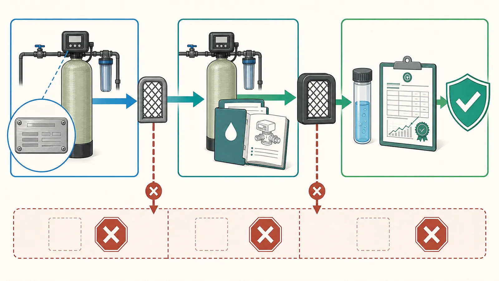
Identify the manufacturer and complete model from the nameplate, then verify the exact manual or submittal for tank type, drawdown, maximum working pressure, connection, dimensions, and replacement-part support. Record the installed cut-in/cut-out settings and actual drawdown; do not substitute a similar-looking tank or nominal gallon label. Stop for a professional if the label is missing, the shell is corroded, the system uses constant pressure, or pressure settings would change.Start with the nameplate, not the tank’s shape or the large gallon number. A replacement is a compatibility decision: the manufacturer and complete model or model family must lead you to the correct literature, and that literature must agree with the installed pressure range, tank design, drawdown, connection, orientation, dimensions, and maximum working pressure. If you cannot identify those facts, the safe answer is “professional identification first,” not “buy the closest-looking tank.”
This worksheet is for documenting a residential well pressure tank before a purchase or service call. It does not authorize opening a control enclosure, touching live wiring, opening a well, pulling a pump, entering a confined space, removing a tank, disconnecting pressurized piping, operating a relief valve, or changing a pressure switch. Those actions belong to a qualified well or plumbing professional who can isolate, drain, lift, test, and recommission the system safely.
Start with the nameplate, not the gallon label #
Photograph first
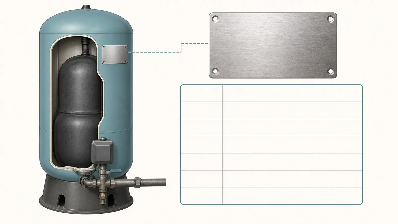
From a dry, stable standing position, photograph the entire tank and then the nameplate, data label, stamped marking, or product sticker. Do not climb on the tank, remove a cover, peel corrosion from a label, or reach behind energized equipment to get a better angle. Take one wide photograph that shows how the tank is installed and several close photographs of every legible marking.
Record the information exactly as printed, including hyphens, letters, suffixes, pressure options, and revision codes. A record that says “80-gallon WellMate” is not an identification. A record such as “manufacturer / WM-20WB / WM0235 QC / serial or date code / label pressure” can lead to the correct table. The distinction matters because a manufacturer may use one family name for multiple designs, connection styles, and pressure or installation options.
| Record from the tank | Write down | Why it matters |
|---|---|---|
| Manufacturer | Determines the literature and parts catalog to search first. | |
| Complete model and suffix | Separates similar-looking models and connection options. | |
| Serial, date, or lot code | Helps the manufacturer or professional resolve an old or discontinued model. | |
| Nominal or total volume | A catalog capacity; it is not automatically usable drawdown. | |
| Tank design or membrane wording | Distinguishes diaphragm, bladder, or air-over-water instructions. | |
| Maximum working or operating pressure | The proposed replacement cannot be below the system’s allowable pressure. | |
| Factory precharge, if printed | A reference value, not permission to change the installed setting. | |
| Connection size and orientation | Determines whether the tank can connect without unsafe or costly re-piping. | |
| Product standard or approval marking | Gives a professional another compatibility and documentation check. |
The last four fields are easy to miss because they may be on a submittal sheet rather than the physical label. That is why the model number is the primary key. Amtrol’s Well-X-Trol page separates diaphragm, full-acceptance bladder, and partial-acceptance bladder designs and provides different manuals, submittals, and replacement-bladder instructions for its product families. Amtrol’s product literature is a useful example of why a visual description such as “red vertical bladder tank” is not enough. Its Well Tank Support guidance also publishes precharge examples by pressure-switch setting, which is a reminder to record the installed cut-in rather than assume a common range.
If the label is missing
Treat an absent, illegible, painted-over, or contradictory label as an identification stop. Photograph the tank, fittings, gauge, control type, and any readable fragments. Then give the professional the approximate outside diameter, height, connection size, orientation, and pressure readings observed at the gauge. Do not infer the model from the tank’s color, stand shape, logo fragment, or nominal gallons.
A professional may be able to trace the model from installation records, a serial code, an old invoice, the tank’s dimensions, and the manufacturer’s archive. If the shell is corroded, dented, leaking, bulging, or damaged, do not clean, sand, tap, lift, or pressure-test it yourself. The replacement decision has become a vessel-condition and safety assessment, not a shopping comparison.
Confirm the tank design and exact manufacturer literature #
Use the model to find the right document
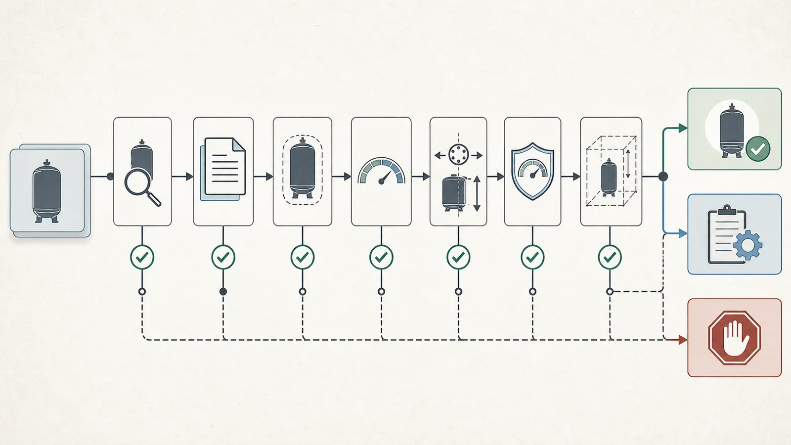
Open the manufacturer’s current support page, installation and operation manual, product submittal, parts list, and any replacement bladder or air-cell instructions for the exact model. Save the URLs or PDFs with your worksheet. If the model is discontinued, ask the manufacturer or a qualified distributor to confirm the successor rather than assuming a newer tank is interchangeable.
The literature should answer these questions:
- Is the vessel a diaphragm tank, a replaceable-bladder tank, or an air-over-water or hydropneumatic design?
- Is the separator or air cell a serviceable part for this exact model?
- What is the manufacturer’s maximum working or operating pressure for this pressure option?
- What are the published tank volume and drawdown or acceptance values at the relevant pressure settings?
- What is the system connection size, thread, connection height, and permitted orientation?
- What are the outside diameter, overall height, base or stand dimensions, and service clearances?
- What precharge does the manual specify, and under what drained and de-energized conditions?
- Are there temperature, water-quality, installation, restraint, or relief-valve requirements?
Do not treat the word “bladder” as a complete compatibility answer. A bladder tank can still have a different connection, pressure rating, orientation, drawdown chart, or replacement-part design. Amtrol’s published model-specific submittal data, for example, lists model number, tank volume, maximum acceptance volume, tank height, diameter, system-connection dimensions, connection size, maximum working pressure, and factory precharge as separate fields. Amtrol’s WX submittal data shows the level of detail to look for; it does not approve a different model.
Pentair’s WM-series table makes the same point from another product family. The table lists capacity, maximum operating pressure, drawdown, diameter, overall height, inlet/outlet height, and connection by model. Its entries show why two tanks that appear to have similar gallon labels can differ in usable water, connection size, or the space required to install them. Pentair’s WM-series specifications must be read by exact item number and configuration.
Identify the separator without opening the vessel
The tank’s design should come from the nameplate and exact manufacturer literature. Use that documentation to determine whether the vessel is listed as a diaphragm, bladder, or air-over-water/hydropneumatic design; do not infer the construction from color, shape, or a loose use of the word “bladder.” Amtrol’s product page separates diaphragm, full-acceptance bladder, and partial-acceptance bladder families and links the relevant literature. Amtrol’s product literature is the appropriate model-first reference.
If the exact literature names an air-volume-control or other air-management component, record that component and its model-specific instructions. Pentair’s WellMate FAQ says an air-volume control converts a UT-series tank to its HP hydropneumatic configuration. That is a product-family fact, not a universal field rule. Pentair’s WellMate FAQ is the correct place to verify that family’s terminology.
Do not depress the air-valve pin or open a drain to “see what comes out” as an identification test. A service check on an unidentified tank does not establish whether the shell, fitting, relief protection, or replacement part is safe. If a professional performs a model-specific check, record the exact procedure and result rather than treating it as a substitute for the nameplate and manufacturer literature.
Record the system pressure and physical constraints #
The replacement must fit the installed system, not just the space on a retailer’s product page. Make a second pass around the tank from a safe observation position and record the following without removing covers or fittings.
Pressure and control type
For a conventional fixed-pressure well system, record the pressure gauge reading when the pump stops and when it starts again. These are the observed cut-out and cut-in values. Do not guess “30/50” or “40/60” because those are common labels. The installed pressure switch, gauge accuracy, pump behavior, and professional records control the actual system.
If the system uses a variable-speed pump, electronic drive, pressure transducer, constant-pressure controller, or a control panel instead of a conventional pressure switch, stop the ordinary worksheet at this point. A controller may change pump speed as demand changes, so the conventional cut-in/cut-out tank comparison is not the right decision model. The replacement must be selected from the pump/controller manufacturer’s current instructions. A conventional tank sized from a generic pressure-switch table can be wrong even if the plumbing connection looks familiar.
Do not open the pressure-switch or controller enclosure. Do not test live wiring, measure voltage, reset overloads, bypass a control, or change the cut-in or cut-out screws. A homeowner may record a visible gauge reading; a qualified professional must diagnose or alter the control system.
Connection and orientation
Record what you can see:
- connection nominal size and whether it appears male, female, quick-connect, flanged, or part of a tank-tee assembly;
- vertical or horizontal orientation;
- where the connection sits relative to the floor and the tank body;
- the direction of nearby pipe runs, valves, unions, check valves, drain, gauge, pressure switch, and relief valve;
- whether there is a service union or a valve that isolates the tank;
- whether the proposed tank can be moved into the room and positioned without removing doors, walls, or unrelated equipment.
Do not identify thread type by forcing a wrench or trial-fitting a part. A wrong thread or connection can damage the tank or create a leak. Have the professional verify actual connection type and any adapter requirement.
Dimensions and service space
Measure only from an accessible position and only if the measurement does not require touching or leaning on the tank. Record outside diameter, overall height, clearance above the tank, clearance around the connection, base or stand footprint, and the path needed to remove the old vessel. Add the height of the tank tee or connection assembly if it affects the ceiling or shelf.
The old tank’s footprint is evidence of what once fit, not proof that every replacement will fit. A different tank may have a taller body, a lower connection, a wider stand, or a different service orientation. Pentair publishes “height inlet/outlet to floor” separately from overall height in its WM table; that is exactly the kind of dimension that prevents a replacement from landing at the wrong elevation. Pentair’s WM-series table supports recording these dimensions separately.
Separate nominal volume from drawdown #
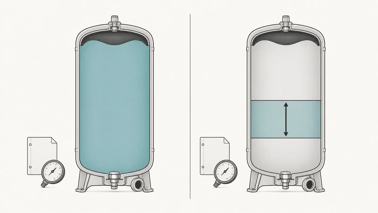
This is the most important comparison in the worksheet. Nominal or total tank volume is the catalog size of the vessel. Drawdown, acceptance volume, or usable storage is the amount of water delivered during the operating pressure band. They are related, but they are not interchangeable.
The Water Systems Council states that total tank volume is not a measure of acceptance volume or drawdown and that total volume varies by tank type. Its sizing sheet relates selection to pump capacity and pressure-switch settings, then uses an acceptance factor to connect the required available water to a total tank volume. Water Systems Council’s pressure-tank sheet is useful for the vocabulary and calculation structure; its own guidance is not a substitute for the exact installed product’s chart or local requirements. For precharge, use the exact model’s instructions and the documented installed cut-in: Amtrol’s support guidance publishes examples that vary with pressure-switch settings, so a guessed universal setting is not a compatibility check.
The replacement comparison
For each candidate, place these columns side by side:
| Decision field | Existing tank | Candidate tank | Pass condition |
|---|---|---|---|
| Manufacturer and complete model | Exact model or documented successor identified. | ||
| Tank design | Same intended function and compatible manufacturer instructions. | ||
| Nominal or total volume | Recorded for context only. | ||
| Published drawdown at installed pressure band | Meets the documented requirement or professional recommendation. | ||
| Field drawdown observation | Explained, measured, and not contradicted by the candidate chart. | ||
| Cut-in / cut-out or controller range | Candidate is approved for the installed control strategy. | ||
| Maximum working pressure | Candidate rating is adequate; system pressure will not exceed it. | ||
| Connection and orientation | Fits without unsafe or unapproved re-piping. | ||
| Diameter, height, base, and clearance | Fits the room and allows service access. | ||
| Precharge instruction | Exact manual available; no guessed setting. | ||
| Replacement bladder or air-cell support | Confirmed by the manufacturer for this model. |
Use the manufacturer’s drawdown chart at the installed pressure band. The Water Systems Council handbook’s example shows the logic: a pump capacity and a 30–50 psig range lead to a selected total volume and a stated drawdown, with a note that field conditions can change actual values. The Water Systems Handbook, 13th Edition is a planning reference, not permission to transplant the table to a different model.
A bounded field observation
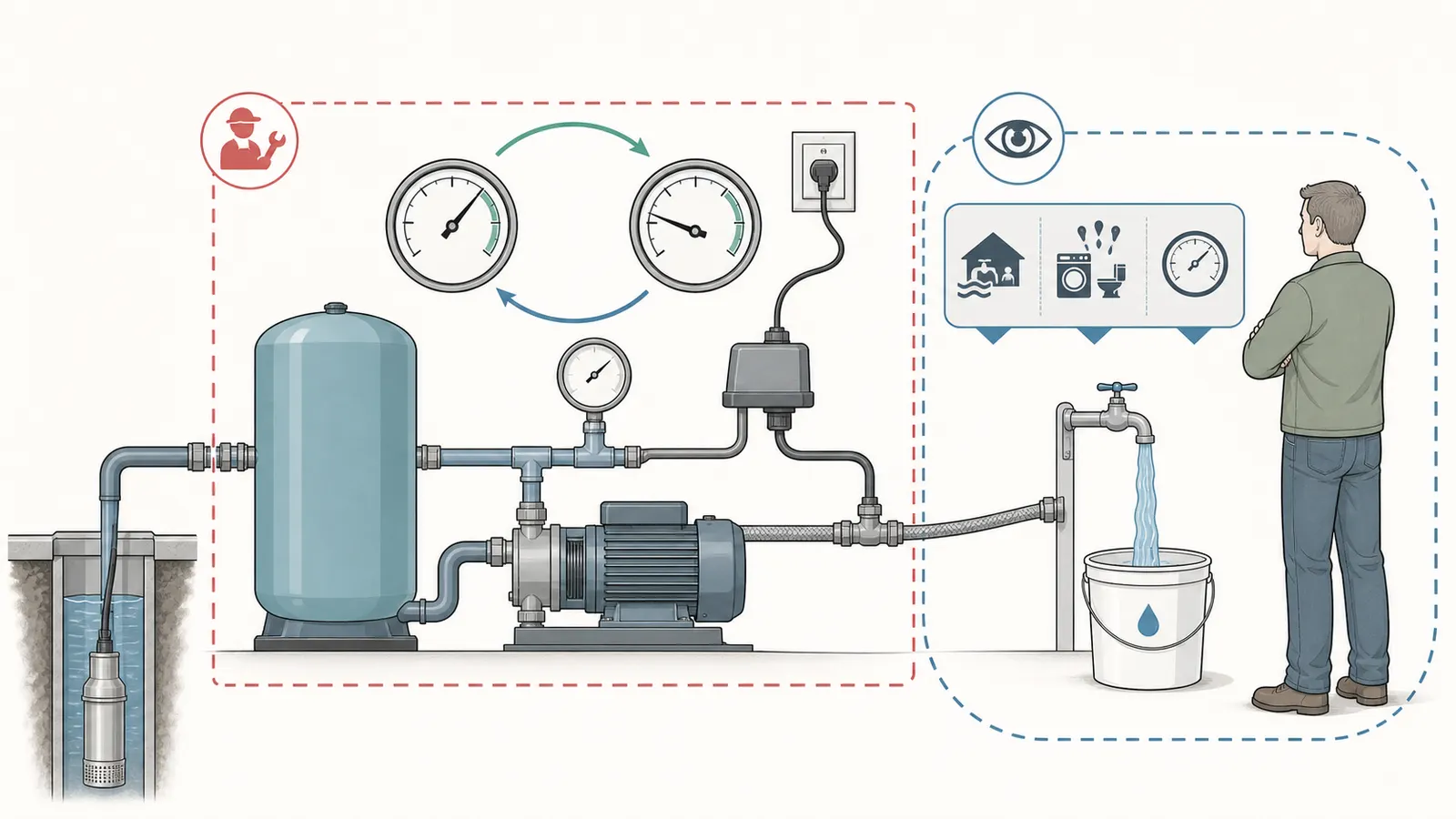
If a professional agrees that the system is safe to observe, a homeowner can help document one ordinary pump cycle without opening a control or changing a valve:
- Note the gauge when the pump has stopped at the high setting.
- Run water through one known fixture or a calibrated flow device while watching the gauge from a safe position.
- Record the gauge reading when the pump starts again and the volume delivered between those two events.
- Stop if the pump does not start, pressure behaves erratically, water quality changes, the gauge is unreadable, or any fitting leaks.
- Give the professional the fixture used, the approximate flow method, the two pressure readings, and whether any other water use occurred.
The measured volume is a field observation of drawdown for that cycle, not a laboratory test or a product certification. Other fixtures, leaks, irrigation, a failing check valve, inaccurate gauge, a pump that continues to contribute flow, or an incorrect pressure-switch setting can distort it. A professional may instead isolate the tank and perform a controlled drawdown test using the manufacturer’s method.
For a simple record, use:
Observed drawdown = water collected from pump cut-out to pump cut-in
Example only: if a professional observes 2.5 gallons delivered while the gauge falls from 60 psi to 40 psi and no other flow is present, record “2.5 gallons observed at 40/60.” Do not convert that observation into a universal tank size, and do not assume a 40/60 tank has the same drawdown as a 30/50 tank with the same nominal label. The pressure band is part of the specification.
Choose recharge, component repair, or whole-vessel replacement #
Identification is complete only when it leads to a bounded next action. Use this matrix after the nameplate, literature, pressure, drawdown, and fit checks are documented.
| Evidence you have | Decision that may fit | What still must be verified | Stop condition |
|---|---|---|---|
| Shell sound; exact manual gives a precharge procedure; symptoms are limited to a documented setting problem | Recharge or correct the setting through a professional or a homeowner procedure explicitly allowed by the exact manual | Power isolation, zero water pressure, correct gauge, correct target, and no shell or separator defect | Any uncertainty about stored pressure, power isolation, or the correct setting. |
| Exact model has a supported replacement bladder or air-cell kit; shell and connections are sound | Replace the internal component through qualified service | Correct kit, installation instructions, lifting method, gaskets, testing, and recommissioning | No exact part support, corrosion, damage, seized connection, or no safe way to isolate and drain. |
| Shell leaks, is corroded, is damaged, is unsupported, or has a failed separator with no supported part | Replace the whole vessel | Candidate model, drawdown, pressure rating, connection, orientation, dimensions, relief protection, and local requirements | Label missing, pressure settings unknown, candidate changes system pressure, or the new vessel cannot be safely installed. |
| System uses constant pressure or variable speed | Controller-specific tank decision | Current pump, drive, transducer, controller, and tank manuals | Any attempt to use a conventional fixed-pressure chart without controller approval. |
Amtrol publishes replaceable-bladder designs for some Well-X-Trol families, while Pentair says an air cell can be replaced in a WellMate tank only after the tank is removed and disassembled. Those are not competing universal answers; they show why the exact model and parts documentation decide whether component repair is available. Amtrol’s Well-X-Trol page and Pentair’s WellMate FAQ support the model-specific branch.
“Recharge” is also not the same as “repair.” If a qualified person documents a pressure-setting issue and the exact manual permits correction, that may be a recharge decision. If the shell is corroded, the tank short-cycles after a documented correction, or the manual says the separator is not serviceable, buying an air pump or adding air is not a replacement decision.
Never use nominal gallons as a shortcut for any of the three branches. A large-looking replacement with a lower pressure rating is not safer. A smaller tank with a similar label may have less drawdown. A tank with a familiar connection may be a different design. A tank that fits the room may not be approved for the pressure range.
Stop points that make this a professional job #
Stored pressure and electrical energy
A pressure tank stores energy in compressed air and pressurized water. A pump system also contains electrical energy near water. Do not open the pressure-switch or controller cover, test live wiring, bypass a safety control, remove a wire, disconnect piping, remove an air-valve core, open a drain, operate a relief valve, or loosen a tank connection as part of identification. Do not rely on a nearby wall switch as proof that a circuit is de-energized.
Manufacturer instructions illustrate the boundary. Pentair says its WellMate air-cell check requires the pump power supply to be turned off and the tank water drained before using a gauge at the valve stem. Pentair’s procedure is product-specific and still involves stored-pressure service. Amtrol’s replacement-bladder instructions require isolation, draining, air release, disconnection, and suitable lifting equipment and state that the product must be installed by a licensed professional. Amtrol’s replacement-bladder instructions are not a homeowner DIY sequence.
Shell condition, confined spaces, and the well
Stop if the tank is corroded, pitted, dented, leaking, bulging, unstable, or installed where a leak could damage the home. Stop if the tank is in a crawlspace, pit, vault, or other location that requires crawling into a confined or poorly ventilated area. Do not enter a well pit, open a well cap, pull a pump, inspect down the casing, or handle well wiring. A professional must evaluate access, lifting, drainage, electrical isolation, and the integrity of the vessel and piping.
Pressure changes and relief protection
Do not change the pressure-switch range to make a new tank “work,” and do not choose a candidate whose maximum working pressure is lower than the system can produce. Do not isolate or remove a pressure-relief valve. Requirements for relief protection, tank approval, location, and plumbing vary by jurisdiction and installation type. The Water Systems Council maintains a current pressurized-water-storage-tank standard listing, but a standard listing does not identify an unknown tank or replace local authority. WSC’s pressurized tank standard page is a reference point, not a national installation permit.
If a proposed replacement changes pressure settings, pump operation, relief-valve selection, pipe size, or the controller, have the professional document the complete system change. Do not approve a tank from a quote that lists only “replace pressure tank” without the model, pressure rating, drawdown basis, connection, and fit.
Your replacement worksheet and handoff packet #
Complete this record before comparing prices or requesting a replacement quote. Blank fields are useful: they show exactly what still needs professional confirmation.
Identification
- Manufacturer: ______________________________________________
- Full model, including suffix and pressure option: ______________________
- Serial, date, or lot code: ______________________________________
- Photograph filenames or document links: __________________________
- Tank design stated by label or manual: ____________________________
- Nominal or total volume: ______________________________________
- Maximum working or operating pressure: ____________________________
- Factory precharge, if documented: _________________________________
- Supported replacement bladder or air-cell part: _______________________
Installed system
- Gauge reading when pump stops: __________ psi
- Gauge reading when pump starts: __________ psi
- Control type: fixed pressure switch / constant pressure / unknown
- Pump make, model, and flow information if available: _________________
- Pressure tank connection size and type: ____________________________
- Tank orientation: ______________________________________________
- Approximate outside diameter: __________ in
- Approximate overall height: __________ in
- Connection height and nearby clearance: ____________________________
- Service union or isolation arrangement visible: ______________________
- Relief valve visible and unobstructed: yes / no / unknown
Drawdown and condition
- Single fixture or test method used: ________________________________
- Other water use during observation: yes / no / unknown
- Volume from cut-out to cut-in: __________ gallons / not measured
- Pressure range during observation: __________ to __________ psi
- Pump cycling, leaking, rusty water, or unusual noise: ________________
- Shell corrosion, dent, bulge, or leak: none visible / present / unknown
- Water quality change after work or repair: yes / no / not applicable
Candidate comparison
- Exact candidate manufacturer and model: ____________________________
- Candidate design: ______________________________________________
- Candidate published drawdown at installed pressure band: _____________
- Candidate maximum working pressure: ______________________________
- Candidate connection and orientation: ______________________________
- Candidate diameter, height, base, and service clearance: _____________
- Exact installation manual or submittal: ______________________________
- Local permit, code, approval, or licensed-work check: ________________
- Professional’s stated reason this candidate is compatible: _____________
Bring the completed worksheet, photographs, prior invoices, pump information, and any controller or pressure-switch model to the well professional. Ask the quote to identify whether the recommendation is a recharge, supported internal component replacement, or whole-vessel replacement. Ask which published drawdown value was used, at which pressure settings, and how the connection and maximum working pressure were checked.
After a tank or well-system component is repaired or replaced, watch for loss of pressure, rapid cycling, leaks, unusual pump behavior, or a change in water color, taste, or odor. EPA advises private-well owners to test after replacing or repairing part of a well system and after water-quality changes, while local health authorities determine the appropriate contaminants and response for the location. EPA’s private-well guidance supports that follow-up without creating a one-size-fits-all testing schedule.
The decision is ready when the model is documented, the exact literature is saved, drawdown is separated from nominal volume, pressure and connection constraints are matched, and every unresolved item has a named professional owner. If any of those gates is blank—especially the model, shell condition, pressure rating, or control type—pause the purchase.
Cite this guide
Brictale. “How to Identify Your Well Pressure Tank Before Replacing It.” Published 2026-09-06; updated 2026-09-06.
https://brictale.com/water/pressure-tanks/identify-well-pressure-tank-before-replacement · Read the Markdown version
Sources and scope
Evidence behind this page
- Amtrol's Well-X-Trol support page states that well-tank precharge depends on the pressure-switch cut-in setting and publishes different precharge examples for different cut-in/cut-out pairs.
Amtrol's Well-X-Trol support guidance; it is not a universal precharge rule for every tank design or controller.
Accessed · Link to this claim - Amtrol lists distinct Well-X-Trol diaphragm, full-acceptance bladder, and partial-acceptance bladder designs, and its product page links separate manuals, submittals, and replacement-bladder instructions.
Amtrol — Well-X-Trol Pressure Tanks
Amtrol Well-X-Trol product families; the page supports using the exact design and model literature rather than inferring construction from appearance.
Accessed · Link to this claim - Amtrol states that maximum working pressure varies by model and publishes system connection, factory precharge, and temperature information in model-family specifications.
Amtrol — Well-X-Trol Pressure Tanks
Amtrol's commercial Well-X-Trol product page; specifications must be checked against the exact model and pressure option.
Accessed · Link to this claim - Amtrol's model-specific ASME submittal data identifies model number, tank volume, maximum acceptance volume, dimensions, system connection, maximum working pressure, and factory precharge as separate data points.
Amtrol — Well-X-Trol WX-440C–WX-460C Submittal Data
The cited WX-440C–WX-460C submittal family; the data demonstrate the fields needed for comparison and do not identify another model.
Accessed · Link to this claim - Pentair's WellMate WM-series table lists capacity, maximum operating pressure, drawdown, diameter, overall height, inlet/outlet height, and connections by model, showing that tanks with similar capacity labels can have different fit and performance data.
Pentair — WellMate WM Series Tanks
Pentair WM-series product table; listed values apply only to the specific WM models and published product configuration.
Accessed · Link to this claim - Pentair says a WellMate pressure tank is sized by the flow capabilities of the well pump and lists the pressure-switch, gauge, relief-valve, drain, service-isolation, and tank-tee components in its typical installation guidance.
Pentair WellMate FAQ for the WellMate family; it does not establish a universal sizing method for other products or constant-pressure controllers.
Accessed · Link to this claim - Pentair says checking WellMate air-cell pressure requires the pump power supply to be turned off and the water drained from the pressure tank, and it gives a WellMate-specific example of four psi below pump cut-in.
Pentair WellMate air-cell procedure; the product-specific value is deliberately not generalized to all tanks.
Accessed · Link to this claim - Pentair says a WellMate air cell can be replaced, but the tank must be removed from the system and disassembled and the replacement kit supplies instructions.
Pentair WellMate tanks and their replacement air-cell kits; it supports a model-specific parts check and professional-service boundary.
Accessed · Link to this claim - The Water Systems Council distinguishes total tank volume from acceptance volume or drawdown and says total volume varies with tank type; its worksheet relates selection to pump capacity and pressure-switch settings.
Water Systems Council — wellcare Sizing a Pressure Tank
The wellcare pressure-tank sizing sheet for typical private-well systems; local and state guidance supersedes it, and it does not replace exact manufacturer data.
Accessed · Link to this claim - The Water Systems Council's current handbook example selects a diaphragm/bladder tank from pump capacity and a 30–50 psig pressure range, then reports both required total tank volume and drawdown; it notes actual values may vary with field conditions.
Water Systems Council — Water Systems Handbook, 13th Edition, Chapter 1
The handbook's pressure-tank selection table and example; it is a planning reference, not a model-specific replacement approval.
Accessed · Link to this claim - The Water Systems Council identifies ASSE 1099-2022/WSC-PST 2000/2022 as the performance standard for pressurized water storage tanks and lists manufacturers with products submitted as meeting that standard.
Water Systems Council — Performance Requirements for Pressurized Water Storage Tanks
The WSC standards listing; it does not certify an unidentified tank or replace the nameplate and manufacturer documentation.
Accessed · Link to this claim - EPA says private-well owners should test water immediately after replacing or repairing part of a well system and after a change in water quality, and it directs owners to local health authorities for contaminants of local concern.
U.S. EPA — Protect Your Home's Water
EPA private-well protection guidance; it supports a water-quality follow-up reminder and does not set state-specific testing or remediation requirements.
Accessed · Link to this claim - Amtrol's Well-X-Trol replacement-bladder instructions warn that installation requires isolating and draining the tank, removing the air-valve core, disconnecting the system connection, and using suitable lifting equipment, and state that the product must be installed by a licensed professional.
Amtrol — Well-X-Trol WX Series Replacement Bladder Instructions
Amtrol's cited Well-X-Trol replacement-bladder procedure; it supports the article's professional-service boundary and does not govern other manufacturers.
Accessed · Link to this claim