Can a Water Softener Go Before a Well Pressure Tank?
A homeowner decision surface for checking a softener's position, pressure, flow, bypass, regeneration drain, and well-system risk before repiping.
The short answer
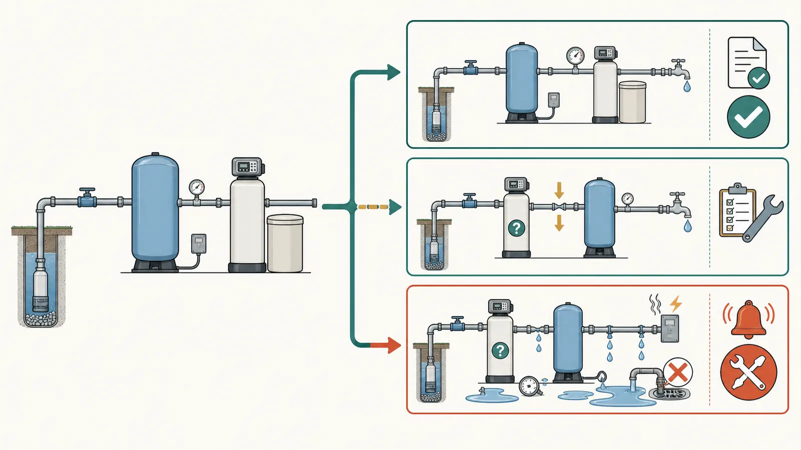
Usually no. For a private well, the safe default is well pump → check valve and pressure controls as installed → pressure tank → treatment. A regenerating softener before the tank can starve the system, reverse-flow during regeneration, or make a restriction affect pump cycling. Map the layout, compare the exact manual's pressure and flow requirements, and get a qualified assessment before repiping.Can a Water Softener Go Before a Well Pressure Tank?
Usually no. For a private well, the safe default is:
well pump → the system's check-valve and pump-control arrangement → pressure tank → treatment → house distribution
A regenerating ion-exchange softener belongs downstream of the pressure tank unless the exact manufacturer instructions and a qualified well-system professional document another design. Whirlpool says a pre-tank softener may receive water only while the pump is running, may allow reverse flow toward the pressure tank during regeneration, and may turn a clog into a pump short-cycling problem. Whirlpool's current installation FAQ is the direct answer to the placement question.
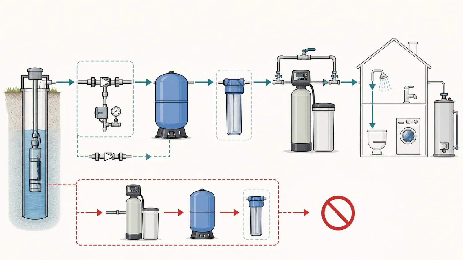
That answer applies to a regenerating softener: a unit with ion-exchange resin, a control valve, a brine or salt tank, a bypass, and a drain for backwash or regeneration. A spin-down separator, cartridge sediment filter, or other coarse-particle device is not automatically the same thing. It still can restrict flow, and its own manual controls its permitted location.
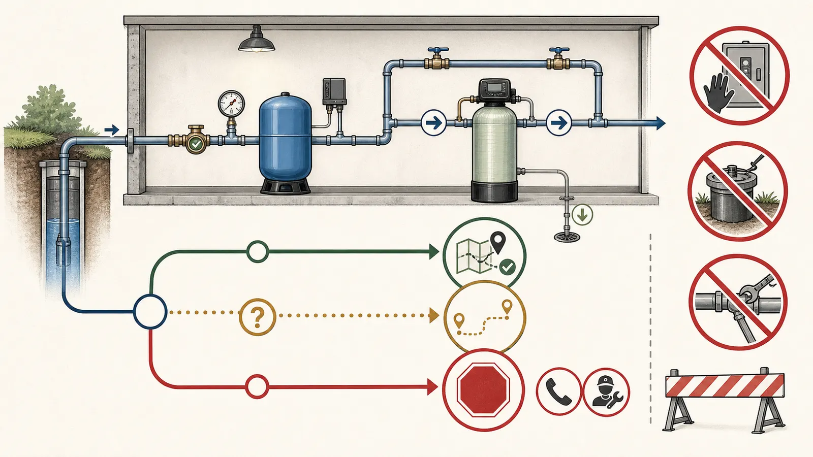
If you discover that an existing softener is before the pressure tank, do not cut or repipe the system from a photo. Map what you can see, record the model and symptoms, compare the manual's pressure and flow gates, and request a qualified repiping assessment. If pressure is stable and the system is not malfunctioning, leaving it alone while you document it is safer than making an unplanned change.
Water-safety boundary: This placement and specification review cannot establish that private-well water is potable, diagnose contamination, or clear the water for drinking. If the water has an abnormal appearance, taste, or odor, or a contamination result is positive or contamination is suspected, arrange appropriate testing with a state-certified laboratory and contact a qualified well professional or local health department, as described in the CDC's well-water testing guidance. If contamination is positive or suspected, follow the CDC's well-water treatment guidance and do not drink the water until the appropriate treatment and testing are complete. A softener placement decision is not a contamination remedy or permission to drink the water.
1. Identify the device before applying the rule #
Start with the equipment, not the pipe order. A homeowner can usually identify the broad device class from the outside without removing covers or opening plumbing.
| Visible clues | Most likely class | What the clues do—and do not—tell you |
|---|---|---|
| Tall mineral tank plus a separate salt/brine cabinet, electronic or mechanical control valve, bypass, and a drain line | Regenerating ion-exchange softener | It needs a regeneration cycle, drain capacity, and the exact manual's pressure and flow. It is the device addressed by the downstream-pressure-tank rule. |
| Media tank with a control valve and a drain, but no salt/brine cabinet | Backwashing filter or conditioner | It is not a softener just because it looks similar. It may have a different backwash demand and pretreatment order. |
| Transparent or opaque housing with a replaceable cartridge and no controller, salt, or regeneration drain | Cartridge sediment filter | It collects particles and can plug. It does not automatically remove dissolved hardness or dissolved metals. Check the cartridge housing and filter manual. |
| Spin-down screen, flush port, or centrifugal separator with no regeneration controller | Coarse sediment separator | It may protect downstream equipment from larger particles, but its allowable pressure, flush method, and placement are product-specific. |
| A tank, controller, brine cabinet, drain, and a label that says iron, sulfur, carbon, or neutralizer | Treatment device that may not be a softener | Do not infer the media or treatment order from the label alone. Find the exact manual and model number. |
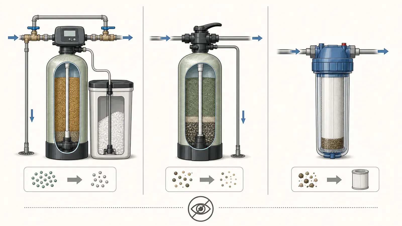
The Avid PWS1 manual is a useful example of why this distinction matters. It describes an ion-exchange softener for hardness that may remove small amounts of “clear-water” iron, but says it is not designed for red-water iron, bacterial iron, particulates, or hydrogen sulfide. For red-water or bacterial iron it specifies an iron filter, and for sediment or turbidity it specifies a backwashing filter; for hydrogen sulfide it only says that the softener will not reduce it. Hydrogen sulfide therefore needs separate water-quality and treatment evaluation rather than an assumption that either of those filters is the prescribed remedy. Those are Avid PWS1 limits, not a universal promise about every softener.
A coarse sediment separator may therefore be part of a sensible well system without being a substitute for a pressure tank or a reason to put a regenerating softener before it. Conversely, calling a backwashing filter a “sediment filter” does not remove its need for adequate backwash flow and a suitable drain.
2. Map the existing system from the outside #
Your goal is an evidence packet, not a remote repair. Use a phone camera, a tape measure only where no pressurized connection is disturbed, and a sheet of paper. Trace the water path by following pipe runs and the inlet/outlet arrows printed on treatment valves. Do not rely on left-to-right appearance; utility-room plumbing often loops around walls or crosses overhead.
Record these items in order, using “unknown” when you cannot confirm one:
- Well entry and pump side. Identify where the well line enters the building or where the pump discharge appears to enter the utility area. Do not open the well cap, casing, pit, or pump housing.
- Pressure tank. Record the tank's label, approximate size, visible gauge, and the pipe connections around it. A tank may be vertical or horizontal, and the largest vessel is not always the pressure tank.
- Pressure switch or other pump control. Photograph the outside label and enclosure only. Note whether a pressure switch, electronic controller, or constant-pressure system is visible. Do not remove a cover.
- Check valve. Note any externally visible valve marked with an arrow, check, one-way, or backflow symbol. Do not assume every well uses the same check-valve arrangement or that an unseen valve is absent.
- Treatment inlet and outlet. Record the model number, arrows, labels, bypass position, brine cabinet, drain line, and any prefilter. Photograph the full assembly and a close-up of the data plate without disconnecting anything.
- House branches. Note whether outside hose bibs, irrigation, geothermal equipment, or a water heater branch appears before or after treatment. Treatment diagrams often leave outdoor water untreated, but the exact configuration is a design choice and should not be inferred from a generic drawing.
- Drain and overflow. Follow the softener's drain hose to its visible destination. Record whether it terminates at a floor drain, standpipe, laundry tub, sump, or pump, and whether an air gap appears to be present. Do not pull the hose out of a drain or test a flood condition.
The outcome should look like this, with uncertainty visible:
| Position | What you see | Evidence quality | Question for service professional |
|---|---|---|---|
| 1 | Well line enters utility room | Seen / inferred / unknown | Is this the pump discharge or an intermediate storage arrangement? |
| 2 | Pressure tank with gauge | Seen / inferred / unknown | Is this the active pressure tank for the house? |
| 3 | Pressure switch or controller | Seen / inferred / unknown | Which device starts and stops or modulates the pump? |
| 4 | Check valve | Visible / not visible / unknown | Where is backflow prevented, and is the arrangement compatible with the treatment? |
| 5 | Softener or filter | Model number recorded / missing | What does the exact manual require? |
| 6 | Bypass and drain | Both visible / partial / unknown | Can the unit be isolated and can regeneration discharge safely? |
Do not confuse a pressure gauge reading with proof that the pressure tank, switch, check valve, pump, or softener is healthy. It is one observation under one set of conditions.
3. Compare the actual layout with the safe default #
For a regenerating softener, compare your map with this sequence:
pressure tank → any permitted pretreatment → softener bypass and control valve → house distribution and water heater
The A. O. Smith AOW-S400/AOW-S500 manual tells installers to place the appliance after the pressure tank and before the water heater. Its well-water installation note specifies a minimum 3/4-inch pipe between the pressure tank and softener for those models. The Avid PWS1 manual likewise says the softener must be after the pressure tank on a private-well system.
These manuals do not create a national plumbing code. They do establish a strong manufacturer default for the product families they cover. Your exact model's manual wins over a general diagram, and state or local plumbing and electrical requirements still apply.
Whirlpool's related multiple-filtration installation guidance also says that, on well water, filtration systems should be installed after the well pump to help prevent short cycling. That is a useful pump-side boundary, but it does not turn every coarse filter into a softener or define one universal order for every treatment train.
What “before the tank” means
There are two common interpretations:
- Treatment between the well pump and pressure tank: this is the concerning arrangement. A restriction or control-valve event is inserted into the pump-to-tank path. A regenerating softener can also have a service, backwash, brine, rinse, or drain state that the pressure-tank system was not designed to see upstream.
- Treatment after the pressure tank but before a branch or water heater: this is the normal homeowner question and is generally the intended placement for a softener, subject to the manual, pretreatment, drain, and flow requirements.
If a softener is upstream of the tank, do not assume the installation is immediately failing. Some systems have unusual storage, booster, or control arrangements. Do assume that the layout deserves a professional review before replacement, repiping, or a new regeneration schedule.
Why regeneration changes the decision
Regeneration is not just a rinse at the faucet. It moves water through a control valve, resin bed, brine circuit, and drain. The A. O. Smith manual states that the drain line carries backwash water during regeneration and calls for an appropriate drain plus an air gap or siphon break to prevent back-siphoning. The Avid manual specifies model-dependent backwash and rinse flow rates and tells the installer to use a drain capable of handling the cycle volume and flow.
The Avid PWS1 specifications list different backwash and rapid-rinse rates by model and total regeneration water use ranging from 41 to 145 gallons across its configurations. That range is not a design allowance for your system. It is a reminder to copy the exact values for the installed model before asking whether a well, drain, pump, and discharge arrangement can support regeneration.
4. Use pressure and flow as specification gates #
Do not ask, “Is 40 psi good?” Ask, “Does the measured pressure and available flow satisfy this exact unit's manual at the point where the unit is installed, including its backwash cycle?”
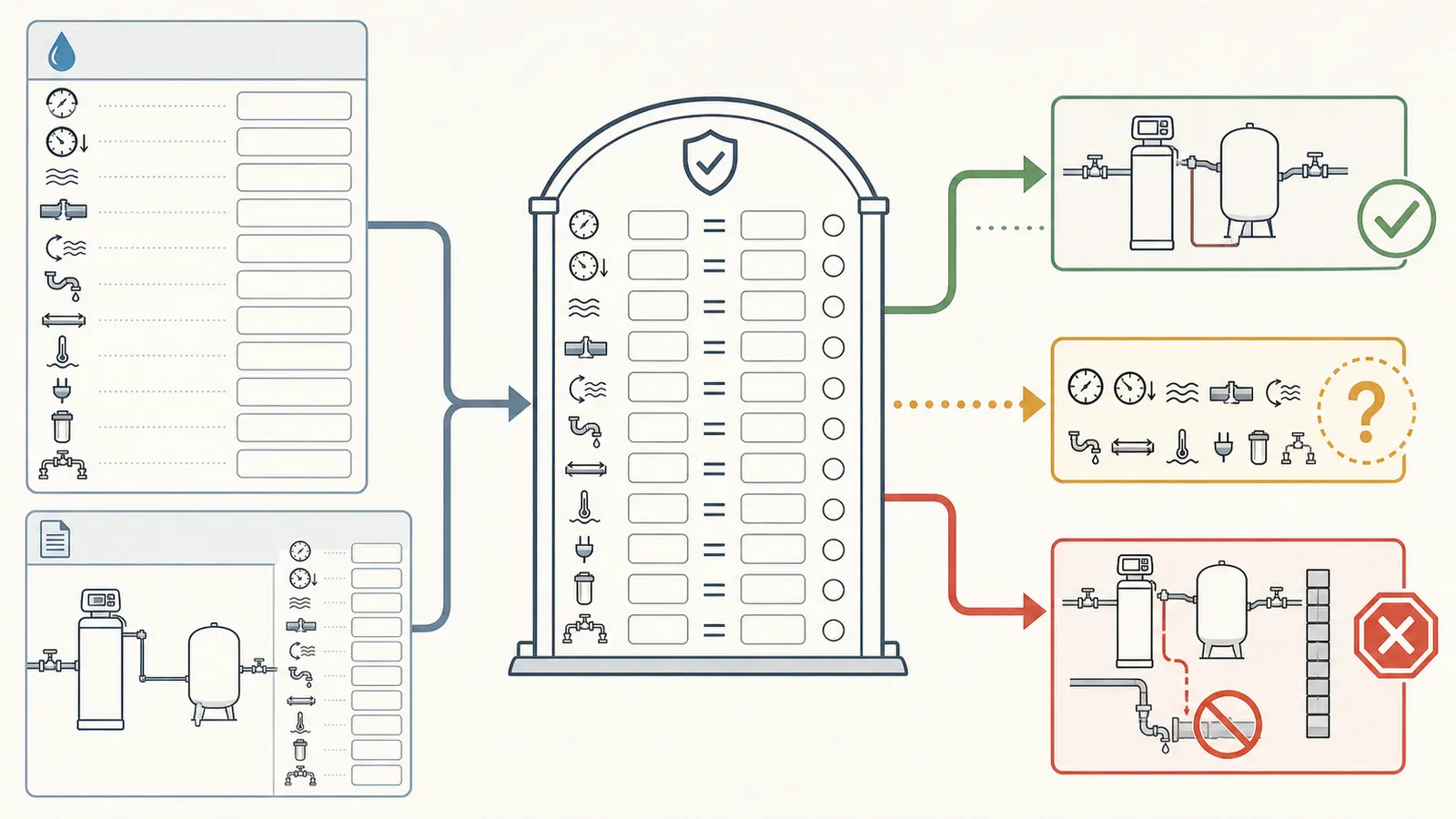
Create a small specification card from the manual:
| Manual gate | Exact value for your model | Your observed or documented value | Pass, missing, or service review |
|---|---|---|---|
| Minimum inlet pressure | ____ psi | ____ psi | ____ |
| Maximum inlet pressure | ____ psi | ____ psi | ____ |
| Minimum pressure for backwash or regeneration | ____ psi | ____ psi | ____ |
| Service flow rate | ____ gpm | ____ gpm | ____ |
| Pressure loss at service flow | ____ psi | ____ psi | ____ |
| Backwash or rapid-rinse flow | ____ gpm | ____ gpm | ____ |
| Regeneration water volume | ____ gal | drain/system capacity ____ | ____ |
| Inlet and outlet pipe size | ____ in | visible size ____ | ____ |
| Drain size, air gap, and discharge limit | manual ____ | visible ____ | ____ |
| Temperature and electrical requirements | manual ____ | visible ____ | ____ |
A homeowner-safe pressure reading
If you already have a suitable hose-thread pressure gauge, follow the gauge and treatment manufacturer's instructions. Whirlpool's current pressure-testing guidance places the gauge at a faucet or fixture close to the well pressure tank, with the home's water use stopped for the reading. Record the time, the gauge's static reading, and whether the pump is running or has recently run. Do not adjust the pressure switch, tank air charge, relief valve, or pump control to make the number fit.
The Whirlpool example range for its products is 20–125 psi, with an ideal range of 50–70 psi. The Avid PWS1 manual lists 25–100 psi for that product family. The A. O. Smith manual has its own model-specific limits and well-water guidance. These differences are exactly why a universal “good pressure” answer is unsafe.
For flow, do not infer well capacity from a single brief faucet stream. A professional well check can include a flow test, pump performance, and pressure-tank and pressure-switch checks. Wellowner.org's annual inspection guidance also identifies pressure loss and frequent pump cycling as reasons to call a well professional sooner.
You may record ordinary household symptoms without creating a test: slow flow at more than one fixture, pressure that falls sharply when a second fixture opens, a softener that stops mid-cycle, a drain pump that runs continuously, or a pump that starts and stops repeatedly. These observations identify a service question; they do not identify whether the cause is the well, pump, pressure tank, check valve, clogged treatment media, restricted plumbing, or a control fault.
5. Check the failure branches without diagnosing them remotely #
Use the matrix to decide what to document and what to do next.
| Observation | What it may indicate | What not to infer | Safest next action |
|---|---|---|---|
| Softener is upstream of the pressure tank | The treatment restriction and regeneration path may be in the pump-to-tank circuit | That the pump is already damaged or that repiping to a stock diagram is safe | Request a qualified well-system and treatment-layout assessment; leave plumbing intact unless there is an active hazard |
| Pressure drops only when a faucet is opened after treatment | Pressure loss through the unit, restricted media, undersized piping, pump capacity, or another fault | That the softener alone is the cause | Record the fixture, gauge location, model, and whether bypass changes the symptom only if the manual makes ordinary bypass use safe; ask for service |
| Pump starts and stops frequently | A restriction, waterlogged or failed pressure tank, pressure-control issue, leak, or other system problem is possible | That changing the softener setting will fix it | Stop experimenting and call a qualified well professional; frequent cycling can damage equipment |
| Regeneration produces an overflowing drain, no drain flow, or a continuous drain | A kink, restriction, valve fault, failed setting, or drain-capacity problem is possible | That the unit is safe to keep regenerating unattended | Follow the manual's homeowner-safe stop or bypass instructions, prevent water damage, and arrange service |
| Low pressure appears only during backwash | The well and pump may not meet the unit's backwash demand, or the device may be restricted | That the pressure tank needs a new air charge | Compare the exact manual's backwash requirement with a professional flow test; do not open controls |
| A coarse separator is before the pressure tank | It may be a different device with a different purpose and manual | That it is harmless because it has no salt | Check its pressure-drop and restriction requirements; get a layout assessment if it is in the pump-to-tank path |
| Bypass raises pressure or changes water quality | The treatment path may add restriction or be malfunctioning | That bypass proves the well pump and tank are healthy | Record the before/after observation and model; have the entire system evaluated |
| No model, manual, or drain route can be identified | The installation cannot be compared to its design requirements | That a generic softener diagram is enough | Pause replacement or repiping until the model and system requirements are documented |
The most important distinction is between a symptom and a mechanism. A pressure dip is a symptom. It could come from the softener, a clogged prefilter, a failing pressure tank, a pump that cannot keep up, a leaking check valve, or a control issue. A photo cannot separate those causes.
6. Decide: leave it alone, monitor, or obtain a repiping assessment #
Use this conservative decision path:
A. Is the device a regenerating softener?
- No or unknown: do not apply the softener rule. Identify the device and manual first.
- Yes: continue.
B. Is it downstream of the pressure tank?
- Yes: continue to the specification and drain gates.
- No or unknown: request a qualified assessment before repiping or replacing the unit.
C. Do pressure, flow, drain, pipe size, electrical supply, temperature, and pretreatment all match the exact manual?
- Yes, with stable operation: document the layout, maintain the unit to the manual, and keep the records with the well file.
- No or missing: obtain a service review. Missing data is not a pass.
D. Are there active warning signs?
Active leaking, flooding, electrical odor, visible arcing, loss of water pressure, repeated pump cycling, an overflowing regeneration drain, or a treatment vessel that is moving or cracking moves the decision to prompt professional service. If there is immediate electrical or flooding danger, stay clear of the equipment and use the appropriate emergency or utility response.
Leaving an existing layout alone pending service is reasonable when the system is stable, there is no active leak or electrical hazard, and you are not trying to install a replacement or change its regeneration settings. “Leave alone” means monitor and document; it does not mean certify the layout as correct.
7. Prepare a safe professional handoff #
Bring this packet to a well/pump professional or water-treatment installer who is willing to evaluate the whole arrangement:
- photos of the complete pipe path, tank, gauge, visible control or switch enclosure, treatment labels, bypass, and drain;
- the treatment model and serial number, installation date, manual, warranty information, and any service log;
- your map showing what is confirmed, inferred, or unknown;
- static pressure readings and the conditions when they were taken, without altering controls;
- dates and descriptions of low pressure, short cycling, regeneration, drain, or bypass symptoms;
- well construction and pump records, prior flow tests, pressure-switch settings if already documented, and prior repairs;
- the manual's minimum and maximum pressure, service flow, backwash flow, pressure loss, drain, pipe, temperature, and electrical requirements;
- the intended treatment objective: hardness, iron, manganese, sediment, odor, or another measured issue.
Ask the professional to answer these questions in writing:
- Is this actually a regenerating softener, a backwashing filter, a cartridge filter, or another device?
- Where is the active pressure tank, and where are the pump control and check-valve functions in this system?
- Does the existing device sit upstream or downstream of the pressure tank, and does that match its exact manual?
- Does the well/pump system meet the device's service and regeneration flow requirements without causing short cycling?
- Is the drain, air gap, overflow, bypass, and discharge arrangement appropriate for the exact model and local requirements?
- If repiping is recommended, what will be isolated, what will remain untreated, and how will the system be tested afterward?
Do not open energized controls, test live wiring, open the well cap or casing, pull a pump, enter a well pit or other confined space, disconnect pressurized plumbing, adjust a pressure switch, alter a pressure-tank air charge, remove a relief valve, or handle treatment chemicals as a remote homeowner diagnostic. Assign those tasks to a qualified professional. The Wellowner.org inspection guidance specifically places pump performance, electrical checks, and pressure-tank and pressure-switch contact checks within professional well-system evaluation.
The decision is therefore not “softener before tank: yes or no from a picture.” It is: a regenerating softener should normally be downstream of the well pressure tank; a pre-tank layout deserves assessment; and a stable system should be documented and left intact until the exact device, pressure, flow, drain, and pump-control relationships are verified.
Cite this guide
Brictale. “Can a Water Softener Go Before a Well Pressure Tank?.” Published 2026-09-04; updated 2026-09-04.
https://brictale.com/water/softeners/water-softener-before-well-pressure-tank · Read the Markdown version
Sources and scope
Evidence behind this page
- Whirlpool Water Solutions says that on a private-well system a water softener should be installed downstream of the pressure tank because the unit otherwise sees water only while the well pump is running, regeneration can send water backward through the outlet toward the pressure tank, and a clogged unit can contribute to pump short-cycling.
Why can't my softener be installed BEFORE the pressure tank?
Whirlpool Water Solutions installation guidance for its softeners on private wells; use as a preferred installation rule and failure-mode explanation, not as a substitute for the exact product manual or local requirements.
Accessed · Link to this claim - Whirlpool Water Solutions says filtration systems used with well water should be installed after the well pump to help prevent short-cycling that could damage the pump.
In What Order Do I Install Multiple Filtration Systems?
Whirlpool Water Solutions guidance for its treatment products; it supports keeping restrictions downstream of the pump but does not define one universal order for every filter type or well design.
Accessed · Link to this claim - The A. O. Smith AOW-S400/AOW-S500 manual instructs installers to place the appliance after the pressure tank and before the water heater, and specifies a minimum 3/4-inch pipe between the pressure tank and softener for well water.
A. O. Smith AOW-S400/AOW-S500 Installation Instructions and Owner's Manual
A. O. Smith AOW-S400 and AOW-S500 model manual; the 3/4-inch and placement instructions are model-specific and are not a national plumbing rule.
Accessed · Link to this claim - The A. O. Smith AOW-S400/AOW-S500 manual gives model-specific pressure and flow gates: well pressure greater than 40 psi and less than 120 psi in its pre-installation guidance, at least 2.0 gpm recommended supply flow, and model-dependent regeneration drain flow and minimum backwash flow.
A. O. Smith AOW-S400/AOW-S500 Installation Instructions and Owner's Manual
A. O. Smith model-specific installation and specification values; use the exact manual for the installed model and do not generalize these psi or gpm values to another unit.
Accessed · Link to this claim - The A. O. Smith manual states that the drain line carries backwash water during regeneration and requires an appropriate drain with an air gap or siphon break to prevent back-siphoning.
A. O. Smith AOW-S400/AOW-S500 Installation Instructions and Owner's Manual
A. O. Smith softener installation requirements; drain configuration remains subject to the exact unit manual and applicable plumbing requirements.
Accessed · Link to this claim - The Avid PWS1 manual says the softener must be installed after the pressure tank on a private-well system; for pretreatment it distinguishes an iron filter for red-water or bacterial iron from a backwashing filter for sediment or turbidity, and says any in-line filter before the softener must not restrict the pressure or flow required for backwash.
Avid PWS1 Series Installation Instructions and Owner's Manual
Avid PWS1 Series manual; placement and pretreatment guidance is for that product family and does not decide the layout of another manufacturer's device.
Accessed · Link to this claim - The Avid PWS1 manual describes the unit as an ion-exchange softener for hardness that may remove small amounts of clear-water iron, but says it is not designed for red-water iron, bacterial iron, particulates, or hydrogen sulfide. It specifies an iron filter for red-water or bacterial iron and a backwashing filter for sediment or turbidity; for hydrogen sulfide it only says the softener will not reduce it.
Avid PWS1 Series Installation Instructions and Owner's Manual
Avid PWS1 application guidance; the stated clear-water iron allowance and exclusions are product-specific, not a universal softener performance claim.
Accessed · Link to this claim - The CDC says private-well owners are responsible for testing their water, recommends testing when water's color, taste, or smell changes, and directs owners to a state-certified laboratory; local or state health departments can help identify testing resources.
Guidelines for Testing Well Water
CDC guidance for private well-water testing; this supports the page's testing boundary and does not diagnose a particular home's water quality.
Accessed · Link to this claim - The CDC says that if private-well water is contaminated with harmful germs or chemicals, or contamination is suspected, owners should not drink it; they should contact the local health department for specific advice, treat the water, and test again to confirm the treatment worked before drinking or using it.
Guidelines for Treating Well Water
CDC guidance for private well-water treatment and suspected contamination; it supports a safety boundary and does not diagnose a particular home's water quality.
Accessed · Link to this claim - The Avid PWS1 manual lists a 25-100 psi site-pressure range and says a vacuum breaker should be considered to prevent tank damage and flooding if a faulty check valve in a private well creates a vacuum.
Avid PWS1 Series Installation Instructions and Owner's Manual
Avid PWS1 site requirements and installation caution; the pressure range and vacuum-breaker note are model-specific and do not prove that a particular home has or needs a check valve in a given location.
Accessed · Link to this claim - The Avid PWS1 specification tables show model-dependent service flow, pressure loss, backwash and rapid-rinse flow, and total regeneration water use; for example, listed backwash and rapid-rinse rates vary by model and the tables list total water use from 41 to 145 gallons across configurations.
Avid PWS1 Series Installation Instructions and Owner's Manual
Avid PWS1 specification tables; the range is illustrative of model variation and must not be used as a substitute for the installed model's table.
Accessed · Link to this claim - Wellowner.org, the National Ground Water Association's consumer guidance, says annual well-system evaluation should be performed by a licensed or certified professional and can include a flow test, pump motor performance checks, and pressure-tank and pressure-switch contact checks; it identifies loss of pressure and frequent pump cycling as reasons to call a professional sooner.
Annual Water Well Inspection - Annual Checkup
National Ground Water Association consumer guidance for private domestic wells; licensing, inspection, and code requirements vary by state and locality.
Accessed · Link to this claim - Wellowner.org advises owners to maintain water softeners and conditioners according to the manufacturer's instructions and to replace or recharge filters as required by the manufacturer and incoming-water quality.
Annual Water Well Inspection - Annual Checkup
National Ground Water Association consumer maintenance guidance; it does not prescribe a maintenance interval for an unidentified treatment unit.
Accessed · Link to this claim - Whirlpool Water Solutions recommends measuring well-water pressure at a faucet or fixture close to the pressure tank before installing its softener and publishes an example product range of 20-125 psi with a recommended ideal range of 50-70 psi.
How to Test Incoming Water Pressure
Whirlpool's current pressure-testing guidance and its product specifications; the ranges are not universal and the installed model's manual controls.
Accessed · Link to this claim