Can Two Water Softeners Share One Brine Tank? A Model-Specific Decision Worksheet
A model-by-model worksheet for deciding whether two water softeners can safely share one brine tank, including media, brine controls, timing, floats, and drains.
The short answer
Two softeners should share one brine tank only when their exact valves, media, brine controls, regeneration timing, safety floats, and drain layout are proven compatible and the manufacturers approve the configuration. A purpose-built twin system is not the same as teeing together two independent valves. If any model, dose, cycle, overlap, safety, or drain field is unknown, use a second brine tank or have a qualified water-treatment professional design the system.Can Two Water Softeners Share One Brine Tank?
Yes, a shared brine tank is technically plausible in a purpose-built twin system. That does not make it safe to tee two independent water-softener valves into one tank. The decision depends on the exact valve models, the media in each mineral tank, each valve's salt dose and fill controls, whether regeneration can overlap, the number and type of safety controls, and the drain arrangement.
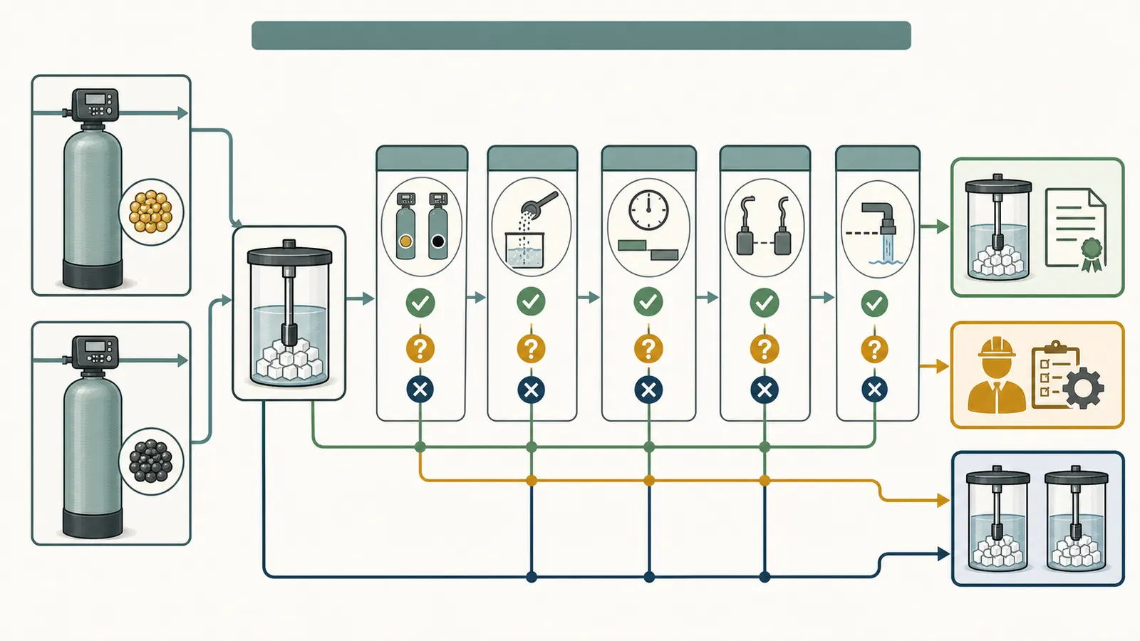
For a homeowner, the practical rule is simple: treat a shared tank as an engineered configuration that needs model-specific approval. If you cannot document every gate in the worksheet below, a second brine tank—or a purpose-built twin system—is the safer choice. Do not use “the fittings connect” or “both units use salt” as a compatibility test.
The distinction matters because a complete twin system is designed to coordinate two media tanks. Water-Right's manual, for example, describes an online tank transferring service to a standby tank while the depleted tank regenerates, then returning to standby. That is a complete control sequence, not a recommendation to combine two unrelated controllers. (Water-Right Twin System installation and owner's manual)
The decision in one view #
| Gate | Record or verify | Pass means | Stop or escalate when |
|---|---|---|---|
| 1. Identity | Exact valve model, revision, media type, media volume, and tank size for A and B | Both manuals describe the intended softener use and the media is suitable for the valve and tank | A model number is missing, a label is unreadable, or one unit is a filter or specialty media system |
| 2. Brine dose | Salt dose per regeneration, injector, brine-line flow control, safety-brine-valve flow control, and refill setting | One tank can supply the correct brine volume for both systems without either valve changing the other's dose | The doses are unknown, contradictory, or depend on a shared part that neither manufacturer documents |
| 3. Cycle behavior | Backwash, brine draw, slow rinse, rapid rinse, refill, and service order for both valves | The cycles are staggered and the tank is never asked to draw and fill in conflicting ways | Either valve can regenerate immediately, pre-fill unexpectedly, or start while the other is drawing or filling |
| 4. Safety | A correct safety float or an approved equivalent for every brine-control path, plus overflow routing | A failed fill or control fault has a documented way to limit or route water | One float is expected to protect two unrelated valves, or overflow would discharge onto the floor |
| 5. Drain and water supply | Drain flow, drain-line size, air gaps, water pressure, and simultaneous demand | The drain and supply can handle the approved sequence under local requirements | Drain capacity is unknown, lines are tied together without approval, or local code questions remain |
| 6. Approval | Written confirmation from the valve and system manufacturers or a qualified water-treatment designer | The exact proposed arrangement is accepted, including programming and service implications | Approval is only a forum post, a generic sales statement, or an assumption based on a similar-looking valve |
The result is not a laboratory certification. It is a conservative homeowner screen. A “pass” on the first five rows means the configuration is worth taking to the manufacturer or qualified professional; it does not authorize plumbing work by itself.
1. Identify both valves and the media before discussing the brine tank #
Start at the control head, not at the salt tank. Photograph each label without removing a cover. Record the brand, full model number, serial or revision information if visible, valve family, control type, and whether the display is metered, time-clock, or another mode. Then record the mineral-tank diameter and height, the media type, the media volume, the service flow, the backwash flow, and the current programmed capacity.
The reason to be exact is that one valve family may be sold in materially different configurations. Pentair's 2510 SXT page lists the valve for both filter and softener applications and shows configurations with different time-clock or metered controls, injectors, brine valves, and brine-line flow controls. A label that only says “Fleck” or “2510” is not enough to reconstruct the installed brine behavior. (Pentair's Fleck 2510 SXT specifications)
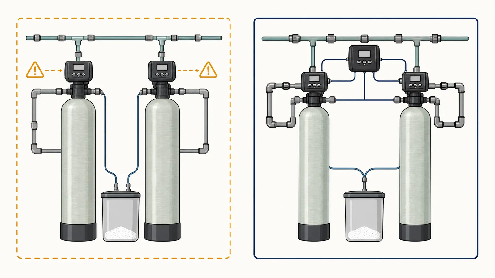
Also identify the media. A conventional cation-exchange softener resin has a salt-brine regeneration cycle. A filter, carbon bed, iron-treatment bed, mixed-media tank, or specialty resin may have a different chemical, flow, or cycle requirement. Penn State describes ordinary water softening as ion exchange and explains that the brine solution is mixed and stored in the brine tank for regeneration. That general description does not establish that every tank using a brine line is interchangeable. (Penn State Extension's water-softening overview)
Use this inventory before you call a dealer:
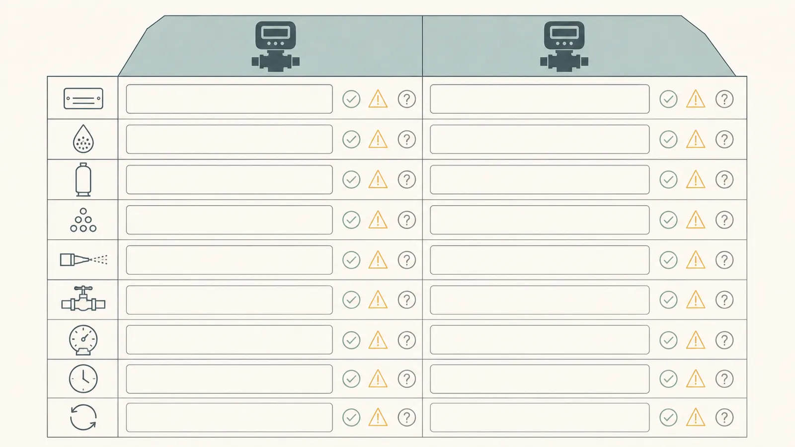
| Field | Valve A | Valve B | Where to verify |
|---|---|---|---|
| Brand and exact model | Control-head label and manual | ||
| Control mode | Display, programming sheet, or manual | ||
| Downflow or upflow | Manual; do not infer from pipe direction | ||
| Mineral-tank diameter and height | Tank label or installation record | ||
| Media type and volume | Installer record, invoice, or service record | ||
| Rated service and backwash flow | Model manual or specification sheet | ||
| Salt dose per regeneration | Job sheet or programming screen | ||
| Injector size | Manual, parts record, or professional inspection | ||
| Brine-line flow control | Manual or identified part | ||
| Refill flow or refill time | Manual and programmed settings | ||
| Regeneration trigger and time | Display and programming settings | ||
| Safety brine valve and float | Brine well, parts list, and manual | ||
| Drain-line flow control and route | Valve and installation inspection |
Do not open the control cover or handle wiring to find these fields. Pentair's service manual says the cover should be removed during installation or maintenance by a qualified service person, warns of electric shock, and directs the technician to disconnect power, isolate the conditioner, and relieve pressure before service. (Fleck 5600 service and safety instructions)
What a missing field means
Unknown is not the same as compatible. If the media volume is unknown, the salt dose cannot be checked. If the valve revision is unknown, the cycle table may not match the installed piston or controller. If the brine-line flow control is not identified, a time-based refill calculation may be meaningless. Mark the field “unknown” and carry it to a professional rather than filling it with a typical value found online.
2. Compare brine dose, fill control, and the two valve cycles #
A brine tank is not just a salt reservoir. Each control valve uses a defined path and a defined sequence to draw regenerant, rinse the media, and refill the tank. The Fleck 5600 job specification sheet separates backwash time, brine and slow-rinse time, rapid-rinse time, brine-tank refill time, drain-line flow control, brine-line flow control, and injector size. Those fields are the mechanical description of what the valve expects. (Fleck 5600 job specification sheet)
For a shared tank, compare the settings side by side. The key question is not “do both valves use the same salt?” It is “can the one tank, its float assembly, and its plumbing deliver the correct brine event to each valve without changing the other valve's event?”
The dose check
Write down each valve's stated salt dose per regeneration. If a manual expresses the setting as pounds of salt, record pounds. If it uses a capacity or percentage setting, record that exact setting and ask the manufacturer how it maps to salt mass. Do not add two capacity numbers and assume the answer is a combined dose; capacity, resin volume, hardness, iron loading, salt efficiency, and reserve settings may all affect programming.
Then identify how the valve controls the brine event:
- Is the draw rate controlled by an injector, an orifice, a brine-line flow control, or a combination?
- Is the refill rate fixed by a flow-control part or calculated from a programmed time?
- Does the safety brine valve include its own flow control?
- Does the manual specify the tank size or media volume that the valve can serve?
- Does the valve use downflow or upflow regeneration, and is that configuration factory-defined?
Clack's WS1/WS1.25 documentation shows why these details cannot be assumed. It describes different regeneration directions and gives the OEM options for pre-fill or post-rinse refill; its cycle tables show that the order changes with those choices. The WS1 product specification separately lists tank application ranges, operating pressure, service and backwash flow, and distinct brine-line and drain-line connections. (Clack WS1/WS1.25 manual; Clack WS1 control-valve specifications)
If Valve A draws a smaller volume over a longer period and Valve B expects a different injector or refill event, a tee may let both access liquid while still delivering the wrong amount to one or both media beds. The failure may not be visible at the salt tank. It can appear later as hard water, salty water, excessive salt use, an overfilled tank, depleted resin capacity, or a regeneration that never completes.
The fill check
Refill is a separate event from brine draw. A valve may refill after the final rinse, or it may pre-fill the tank before regeneration. Clack's manual explicitly documents both options and shows that the cycle order changes with the option. (Clack WS1/WS1.25 cycle options)
For each valve, record:
- Refill-before or refill-after behavior.
- Refill duration or stated flow rate.
- Whether refill water is treated or untreated.
- Whether the valve expects an air check or other brine-well component.
- Whether the refill is controlled by the valve, by a separate brine valve, or by a system controller.
Water-Right's twin-system startup procedure illustrates the level of verification a designed system expects: the installer confirms that the valve draws from the regenerant tank, checks for air leaks or bubbles, then advances to refill and confirms that the tank is refilling. The manual gives 0.5 gpm as the usual residential and light-commercial refill rate for that system. Do not transplant that rate to another brand or model. (Water-Right startup procedure)
3. Prove that regeneration cannot overlap in a harmful way #
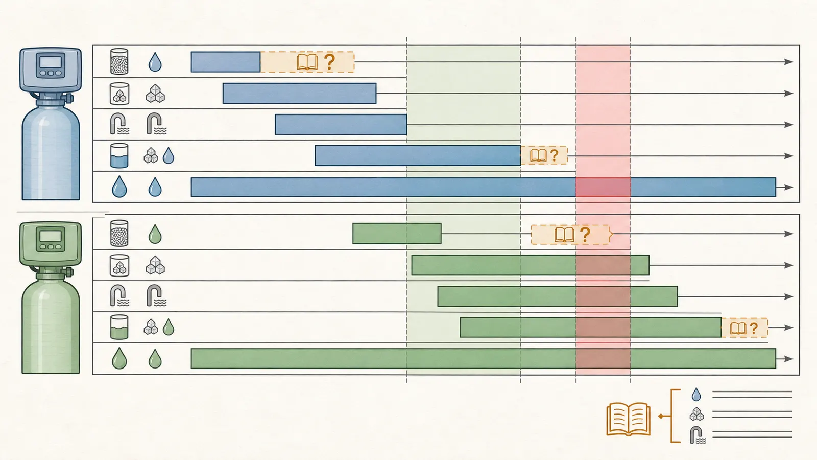
Two independent valves have two independent clocks, meters, controllers, or manual regeneration commands. That is the central compatibility risk. A shared tank can be plausible only if the valves are coordinated so that one does not draw brine while the other is filling, and their backwash or rinse discharges do not exceed the available supply and drain capacity.
Penn State distinguishes scheduled regeneration from demand-controlled regeneration. A time-clock valve may start on its programmed schedule even when the other unit is in service; a demand-control valve may start when its own gallon counter reaches zero. Those triggers are not automatically aware of one another. (Penn State Extension on timed and demand-control softeners)
Make a timing strip for a normal regeneration and a manually initiated regeneration. Use the exact names from each manual, because “brine,” “rinse,” and “fill” may occur in different orders:
| Time from start | Valve A | Valve B | Shared-tank and drain observation |
|---|---|---|---|
| 0–___ minutes | Is A drawing, filling, or backwashing? | ||
| – minutes | Does B start while A is still using brine or drain capacity? | ||
| – minutes | Can either valve be in service while the other regenerates? | ||
| – minutes | Does refill occur before or after rinse? | ||
| End | Does each valve return fully to service? |
The timing screen passes only if all of the following are documented:
- Each valve has a delayed or coordinated start that prevents simultaneous regeneration.
- An immediate regeneration command on one valve cannot unexpectedly start the other valve's brine or fill event.
- The shared tank has time to recover the intended brine concentration before the next draw.
- The drain can accept every backwash and rinse event that can occur in the approved sequence.
- A power outage, clock reset, meter error, or manual regeneration does not create an unreviewed overlap.
A purpose-built twin system handles this differently. Water-Right describes the online tank transferring service to the standby tank before the depleted tank regenerates, and says the two-tank configuration provides uninterrupted conditioned water. That behavior comes from the system's coordinated control logic and plumbing. Two separate controllers connected with a tee do not gain that logic merely by sharing a salt tank. (Water-Right twin-system regeneration sequence)
What not to infer from a quiet test
Do not call the setup compatible because one manual regeneration completed without a leak. A single test may not expose a time-clock conflict, a demand-trigger conflict, a refill-before-regeneration conflict, or a low-salt condition. It also may not reveal a dose error until the media has gone through several cycles.
Do not start a manual regeneration just to watch it unless the manufacturer's homeowner instructions specifically describe a safe procedure for that exact model and the system is not being altered. Never force a valve through positions, disconnect a brine line, or put hands near moving or pressurized parts to observe flow.
4. Check floats, air checks, overflow, and drain paths as separate safety systems #
The brine tank needs more than a shared liquid path. Each valve's brine-control design must be protected against overfill, loss of prime, air leaks, and back-siphonage. A safety float can reduce the chance of an accidental overflow, but it is not a universal substitute for a second valve-specific control path.
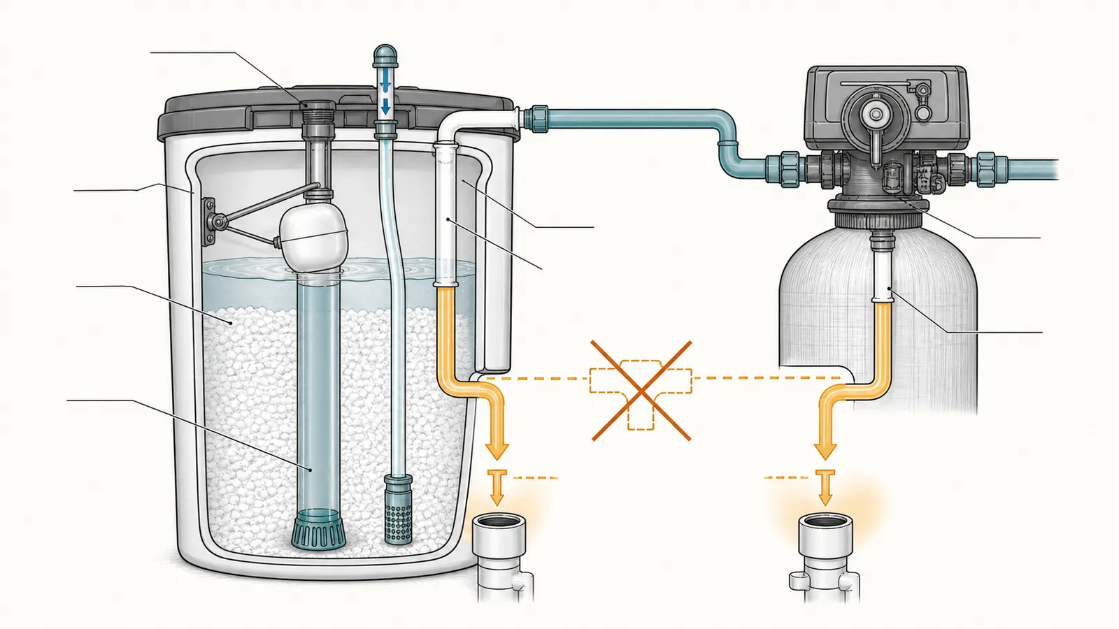
Water-Right directs a tube from the refill elbow to the brine safety float. It recommends an overflow line where an overflow could damage the building, and it says that the overflow line should be a direct, separate line rather than being connected into the control-valve drain line. (Water-Right brine safety and overflow instructions)
Pentair's Fleck 5600 manual identifies the residential air check, brine valve, injector, and brine-line or drain-line flow-control parts as specific components, not generic plumbing ornaments. It also tells the installer to verify brine draw and tank fill during startup, and its troubleshooting material connects failed brine draw or excessive tank water with items such as injectors, flow controls, timers, and the brine valve. (Fleck 5600 startup and troubleshooting guidance)
Use a professional inspection for the following questions:
| Question | Why it matters | Homeowner-safe observation |
|---|---|---|
| Does every brine path terminate in an approved safety-brine-valve or equivalent? | A single float may not control two independent refill commands | Photograph the visible brine-well components; do not remove them |
| Does each valve have the air check or anti-air component its manual specifies? | Air leaks can stop or interrupt brine draw | Look for a labeled part in the manual and service record |
| Is the overflow line separate and gravity-drained? | A failed fill can otherwise discharge onto the floor or share a restricted path | Trace visible tubing without disconnecting it |
| Does each control-valve drain have the required air gap? | Prevents wastewater backflow or back-siphonage | Look at the discharge point; do not insert tubing into a drain or trap |
| Can the drain accept simultaneous worst-case flow? | Backwash and rinse may use more flow than brine draw | Use the manuals' rates for a professional capacity check |
| Is the water pressure within both valves' limits during regeneration? | Low pressure can interrupt brine draw; excessive pressure can exceed component ratings | Read an existing gauge only; do not alter regulators or pressurized fittings |
The manuals are installation instructions, not a substitute for local plumbing requirements. Pentair says plumbing must follow local codes and provides an air-gap and drain-line guide for the Fleck 5600. Water-Right likewise directs attention to applicable plumbing regulations, drain capacity, air gaps, and anti-siphon arrangements. Treat these as installation boundaries, not as a national code summary. (Pentair Fleck 5600 installation limits; Water-Right drain-line instructions)
5. Use the homeowner worksheet to classify the configuration #
Complete the worksheet with the manuals open. A row is “yes” only when you have a model-specific source or written confirmation. “Probably,” “looks similar,” and “a dealer said it should work” are not yes answers.
| Worksheet field | A | B | Evidence or note |
|---|---|---|---|
| Exact valve model and revision | |||
| Softener, filter, or specialty media application | |||
| Media type and cubic-foot volume | |||
| Mineral-tank diameter and height | |||
| Regeneration direction | |||
| Trigger: time clock, meter, or other | |||
| Immediate or delayed regeneration | |||
| Brine draw time and control method | |||
| Salt dose per regeneration | |||
| Injector and brine-line flow control | |||
| Refill timing and rate | |||
| Safety-brine-valve and float part | |||
| Air check or equivalent | |||
| Backwash and rinse flow | |||
| Drain-line route and air gap | |||
| Manufacturer's shared-tank approval |
Now classify each gate:
| Outcome | Use this when | Recommendation |
|---|---|---|
| Green — engineered and approved | Both systems are part of a documented twin arrangement, or the exact proposed shared-tank design has written manufacturer approval and a professional confirms the installation | Proceed only through the approved installation and programming instructions |
| Amber — plausible but unresolved | Model data, dose, timing, safety parts, drain capacity, or local requirements are missing; no exact approval is available | Pause and obtain the manuals, a professional design review, and written confirmation |
| Red — use a second tank or replace with a designed twin system | The valves have incompatible cycle logic, different media requirements, uncontrolled overlap, unknown safety protection, or a drain/supply limit | Keep the systems separate or choose a purpose-built twin configuration |
The worksheet is intentionally conservative because the consequences are not limited to salt waste. A wrong fill can leave too much water in the brine tank. A wrong draw can leave the media under-regenerated. A cycle overlap can reduce pressure or overload a drain. A failed or incorrectly routed overflow can damage the floor, wall, or stored belongings. A back-siphon condition can contaminate the treatment equipment.
Water-quality boundary
That back-siphon warning is about protecting equipment; it is not a test of whether the water is safe to drink. This worksheet cannot determine whether source water is microbiologically safe or safe when its quality is unknown. The CDC says water softeners remove minerals but do not remove parasites, bacteria, or viruses, so a softener is not disinfection. (CDC's home water-treatment guidance)
If harmful germs are suspected, do not drink the water; use bottled water or another known-safe source, contact the local health department, and test after treatment before drinking or using it. Chemical contamination has a stricter boundary: CDC says do not drink or use the water for any purpose, because swallowing, touching, or other contact could be dangerous; boiling does not remove chemicals. Contact the local health department for jurisdiction-specific treatment and testing instructions, and use the testing process or laboratory it recognizes. (CDC's guidance for treating well water) Do not treat a completed regeneration, clear appearance, lack of salty taste, or an intact float as proof of microbiological safety or chemical safety.
A bounded calculation for drain demand
You may estimate whether the drain question deserves immediate escalation, but do not use the estimate as design approval. Record the maximum drain flow for each valve from its manual:
possible simultaneous drain demand = Valve A maximum drain flow + Valve B maximum drain flow
Example with variables only:
A_drain_max + B_drain_max = combined_worst_case_flow
Then ask a qualified installer to compare that worst-case condition with the actual drain line, air gaps, elevation, discharge point, and local requirements. Do not substitute a manufacturer's “continuous service flow” for a backwash or drain flow. Pentair lists separate continuous-flow and maximum-backwash specifications for the 2510 SXT, and Water-Right tells the installer to ensure that the drain can handle the system's backwash rate. (Pentair 2510 specifications; Water-Right drain capacity guidance)
6. Read symptoms without turning them into a compatibility verdict #
A symptom can identify a failed function; it usually cannot identify the exact cause. Use this matrix to decide what to record and what not to touch.
| Symptom | What it may indicate | What to observe | What not to infer | Safest next step |
|---|---|---|---|---|
| Hard water after the conversion | A valve bypassed, a cycle did not complete, a media bed was under-regenerated, or one unit is not serving | Which valve display shows service, bypass position, salt level, and recent error code | That the brine tank is simply too small | Stop the shared arrangement and have the programming and plumbing checked |
| Salty taste after regeneration | Excess brine, incomplete rinse, wrong refill, air leak, or incorrect cycle order | Time of symptom, whether both valves ran, and any manual settings changed | That adding more rinse time is automatically safe | Avoid changing cycle values without the exact manual or professional guidance |
| Brine tank water is higher than expected | Fill control, drain restriction, timer, float, brine valve, or shared refill conflict | Visible water level and whether overflow protection is present | That the float alone proves the tank is compatible | Keep the area dry, place the unit in the manufacturer-approved bypass if instructed, and call service |
| Salt disappears faster than before | Two doses are being delivered, a leak or refill fault exists, or settings changed | Salt additions, dates, programmed dose, and whether both valves regenerated | That high salt use proves the media is working harder | Do not retune by guesswork; have dose and refill measured |
| Drain runs at the same time from two lines | Overlapping regeneration or a shared drain restriction | Which valve is in which documented cycle, without disconnecting lines | That a larger hose automatically fixes the issue | Stop initiating additional regeneration and obtain a drain-capacity review |
| One valve shows an error or loses time | Power, controller, meter, or programming issue can alter regeneration timing | Displayed error, time reset, and whether the outlet is uninterrupted | That the other valve will automatically compensate | Restore only user-level settings named in the manual; use a qualified service person for controls |
The Fleck 5600 troubleshooting guidance links hard water, excessive tank water, failed brine draw, and drain problems to different possible causes, including bypass position, salt level, refill time, flow controls, injectors, timers, pressure, and internal valve issues. That is why a symptom should launch a diagnostic branch rather than a generic “increase the salt” fix. (Fleck 5600 troubleshooting table)
7. Choose the safer practical configuration and prepare the handoff #
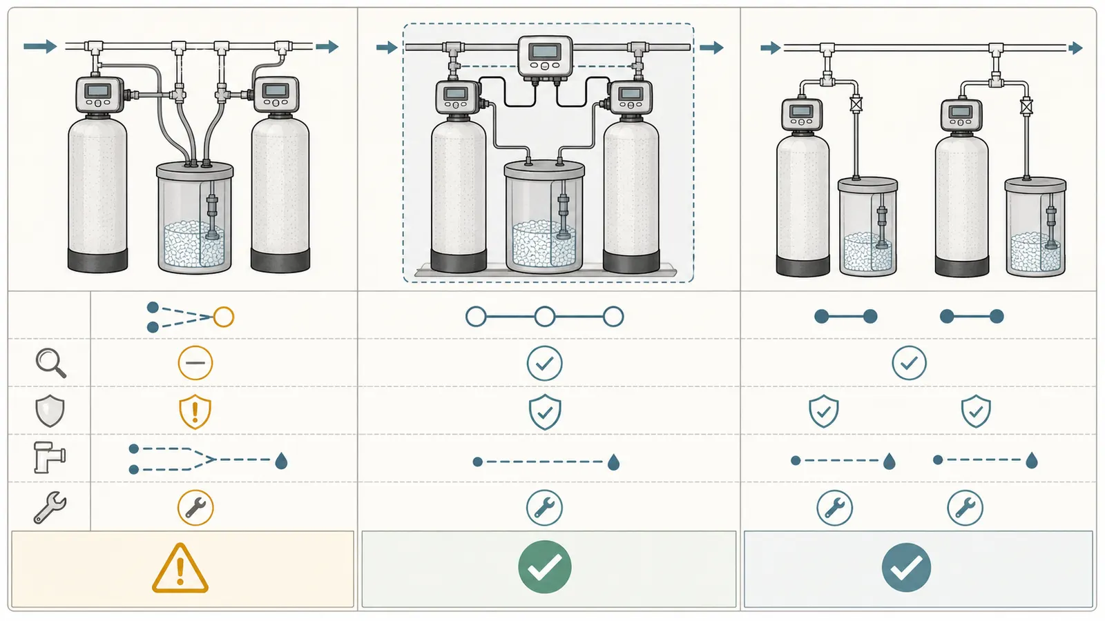
If the worksheet ends amber or red, the practical alternative is usually a second brine tank with each valve retaining its documented brine-control path. A purpose-built twin system is another option when continuous treated-water availability, space, or operating logic justifies a coordinated assembly. A shared-tank retrofit should not be selected solely to save floor space or avoid buying a tank.
| Configuration | Control coordination | Failure isolation | Homeowner decision |
|---|---|---|---|
| Two independent softeners, separate brine tanks | Each system follows its own documented cycle | A problem is more localized and easier to identify | Safer default when models are unrelated |
| Purpose-built twin system | Designed controller transfers service and regenerates the standby tank | Components and sequence are engineered together | Consider when a complete system is warranted |
| Two independent valves, one shared brine tank | Depends on custom synchronization, dose, safety, and drain design | A shared fault can affect both systems | Do not use without exact written approval and professional design |
Before a professional visit, assemble:
- Clear photographs of both control heads, mineral tanks, brine well interiors, visible floats, bypasses, drain outlets, and labels.
- The exact manuals and any installer programming sheets.
- Media type, media volume, tank dimensions, water-hardness result, iron or manganese result if relevant, and household water-use pattern.
- The last three salt additions and the dates of any regeneration or error.
- A sketch showing inlet, outlet, each brine tube, each drain line, overflow tubing, air gaps, and the discharge point.
- The desired outcome: lower salt use, uninterrupted soft water, using an existing tank, or replacing one failed unit.
Ask the professional to answer these questions in writing:
- Are these two exact valve models approved for one brine tank, or is a purpose-built twin controller required?
- What is the combined salt dose and how is each dose metered or limited?
- What prevents simultaneous brine draw, refill, backwash, or rinse?
- What safety-brine-valve or float arrangement protects every refill command?
- Are overflow and control-valve drains separate, correctly air-gapped, and compliant with local requirements?
- What happens after a power outage, meter fault, low-salt condition, or manual regeneration?
- Which settings are homeowner-adjustable, and which service actions require isolation, pressure relief, and electrical disconnection?
Do not open energized controls, test live wiring, disconnect pressurized brine or drain tubing, manipulate a pressure regulator, or force a valve through a regeneration position as a homeowner experiment. Do not enter a confined space, open a well, pull a pump, or alter pressurized well equipment to solve a softener-brine question. Pentair's service instructions specifically require power disconnection, water isolation, and pressure relief before covered service work, and the valve manual says professional installation may be required. (Pentair Fleck service safety instructions)
Maintenance after an approved configuration
An approved shared tank still needs a written maintenance schedule. At each salt check, look for salt bridging or a low-salt condition, keep the tank and surrounding floor dry, and record which valve regenerated. Do not add a resin cleaner or change salt type unless the exact manufacturer permits it; Water-Right cautions that some models do not recommend resin cleaners or cleaning additives in the brine tank. (Water-Right brine-tank maintenance guidance)
At the interval stated by each manufacturer, have the professional verify the brine draw, refill, drain flow, safety float, air check, meter or timer, and return to service. If the system has two independent valves, inspect the timing relationship after any controller replacement, programming change, power event, or plumbing alteration. A shared tank is only as reliable as the least-known component in the sequence.
The final homeowner decision is therefore bounded: share one brine tank only for a documented, coordinated configuration with verified dose, timing, safety, and drain behavior. If the evidence stops at “the valves can be connected,” the evidence has not reached “the valves can regenerate correctly together.”
Cite this guide
Brictale. “Can Two Water Softeners Share One Brine Tank? A Model-Specific Decision Worksheet.” Published 2026-09-05; updated 2026-09-05.
https://brictale.com/water/softeners/can-two-water-softeners-share-one-brine-tank · Read the Markdown version
Sources and scope
Evidence behind this page
- An ion-exchange softener exchanges hardness minerals for sodium or another regenerant ion, and regeneration uses a salt solution to restore the exchange sites; the brine solution is mixed and stored in the brine tank.
Water Softening — Penn State Extension
General ion-exchange softener operation and brine-tank function; not a compatibility approval for two independent valves.
Accessed · Link to this claim - Penn State distinguishes timed softeners, which regenerate on a schedule, from demand-control softeners, which regenerate after a programmed amount of water has been softened.
Water Softening — Penn State Extension
General control strategies; the article does not extend this distinction into a shared-brine design rule.
Accessed · Link to this claim - Pentair lists the Fleck 2510 SXT for filter and softener applications and shows multiple configurations with different timers or meters, injectors, brine valves, and brine-line flow controls.
Fleck 2510 SXT Valve — Pentair
Pentair's listed 2510 configurations; does not establish compatibility with another valve or brine tank.
Accessed · Link to this claim - The Fleck 5600 service manual identifies separate settings for backwash, brine and slow rinse, rapid rinse, brine-tank refill, drain-line flow control, brine-line flow control, and injector size.
Fleck 5600 Service Manual — Pentair
Fleck 5600 service-manual job specification sheet; use only for identifying fields to compare, not for another model.
Accessed · Link to this claim - The Fleck 5600 manual describes a regeneration sequence that includes backwash, brine/slow rinse, rapid rinse, and brine-tank fill, and directs the installer to verify brine draw and refill during startup.
Fleck 5600 Service Manual — Pentair
Fleck 5600 sequence and startup checks; exact steps vary by valve and programming.
Accessed · Link to this claim - The Fleck 5600 manual requires a drain air gap to prevent backflow and gives drain-line sizing guidance based on backwash flow and length; it also says local plumbing codes apply.
Fleck 5600 Service Manual — Pentair
Fleck 5600 installation guidance; not a national plumbing-code statement and not a design approval for combined drains.
Accessed · Link to this claim - The Fleck 5600 manual warns that servicing requires disconnecting power, shutting off or bypassing the conditioner, and relieving pressure; it says the product should be installed by a plumbing professional.
Fleck 5600 Service Manual — Pentair
Pentair safety and installation warnings; used to bound homeowner inspection actions.
Accessed · Link to this claim - Clack's WS1 and WS1.25 documentation says the valves can use demand or time-clock regeneration, can be set for downflow or upflow regeneration depending on model, and can refill the regenerant tank before or after regeneration.
WS1 and WS1.25 Manual — Clack Corporation
Clack WS1/WS1.25 control-valve options; not a statement that an arbitrary WS1/WS1.25 pair may share a tank.
Accessed · Link to this claim - Clack's WS1 documentation lists tank application ranges, operating pressure, backwash and service flow information, and separate brine-line and drain-line connection sizes.
WS1 Water Specialist Valve — Clack Corporation
Clack WS1 product specifications; values are model-family specifications and cannot be substituted for the installed valve's programming.
Accessed · Link to this claim - Clack's manual shows that cycle order differs by regeneration direction and refill option, including separate sequences for downflow or upflow and pre-fill or post-rinse refill.
WS1 and WS1.25 Manual — Clack Corporation
Clack cycle tables; used to show why two independent valves cannot be assumed to have the same timing.
Accessed · Link to this claim - Water-Right's twin-system manual describes a coordinated two-tank arrangement in which the online tank transfers service to the standby tank and the depleted tank regenerates, providing uninterrupted treated water through the designed sequence.
Installation Instructions & Owner's Manual — Water-Right Twin System
A complete Water-Right twin-system design; it is evidence for purpose-built coordination, not authorization for two unrelated valves.
Accessed · Link to this claim - Water-Right directs the brine connection to the brine safety float, says the safety float reduces the chance of accidental overflow, and recommends a separate overflow line where an overflow could damage the building; the overflow line is not to be connected into the control-valve drain line.
Installation Instructions & Owner's Manual — Water-Right Twin System
Water-Right twin-system brine-tank and overflow installation; exact parts and routing must be confirmed for the installed system.
Accessed · Link to this claim - Water-Right says the drain must handle the system's backwash rate, gives a larger drain-line recommendation above 7 gpm, and requires an air gap to reduce the possibility of sewage back-siphoning into the softener.
Installation Instructions & Owner's Manual — Water-Right Twin System
Water-Right installation guidance; local plumbing regulations and the installed system's requirements control.
Accessed · Link to this claim - Water-Right's startup procedure tells the installer to confirm brine draw, then confirm that the brine tank refills; it gives 0.5 gpm as the usual residential and light-commercial refill rate for that system.
Installation Instructions & Owner's Manual — Water-Right Twin System
The cited Water-Right system's refill procedure and typical rate; not a universal refill rate.
Accessed · Link to this claim - CDC says water softeners remove minerals, primarily calcium and magnesium, but do not remove parasites, bacteria, or viruses; different home water-treatment systems remove different germs or chemicals.
About Home Water Treatment Systems — CDC
Public-health boundary for this worksheet; confirms that softening is not disinfection and does not establish any shared-tank compatibility.
Accessed · Link to this claim - CDC says that if well water is contaminated with harmful germs or chemicals, or contamination is suspected, people should not drink it, should use bottled or another safe source, contact the local health department, and test the water after treatment before drinking or using it. For chemical contamination specifically, CDC says not to drink or use the water for any purpose because swallowing, touching, or other contact could be dangerous, and boiling will not remove chemicals.
Guidelines for Treating Well Water — CDC
Public-health response boundary when source-water quality is unknown or contamination is suspected; microbial and chemical contamination require different use restrictions. Not a recommendation about softener plumbing.
Accessed · Link to this claim