What Size Pipe From a Well Pump to a Pressure Tank?
Compare a proposed pipe size from a well pump to its pressure tank using pump connection, flow, friction, elevation, fittings, settings, and local code.
The short answer
Start with the pump’s actual discharge connection: the pipe to the pressure tank is normally no smaller than that connection, then confirm the proposed material and inside diameter against flow, developed length, fittings, elevation, pressure-switch settings, the pump curve, and local requirements. Upsizing can reduce friction; it cannot increase well yield. If the model, flow, or hydraulic inputs are missing, stop and request a documented calculation.The defensible starting point is the pump’s actual discharge connection, not a universal “1-inch” or “1-1/4-inch” rule. For the Sta-Rite shallow-well jet-pump configurations in its manual, Pentair says the pipe from the pump discharge port to the pressure tank must be at least as large as the discharge port. That is a manufacturer minimum for those configurations—not proof that the same nominal size is right for every submersible pump, jet pump, material, run, or local code. Pentair’s pressure-tank connection instructions show why the pump-to-tank connection must be treated as its own pipe section.
For a homeowner comparing a proposed size, use this order: identify the pump type and exact model; record the actual discharge-port size; identify pipe material and inside diameter; measure developed length, elevation, and fittings; establish the flow and pressure-switch settings; compare friction loss against the pump curve; then verify the currently adopted local rule. Upsizing can reduce friction and preserve pressure. It cannot make a low-yield well produce more water. If the model, design flow, water level, or hydraulic calculation is missing, stop sizing remotely and request a documented calculation from the installer or well professional.
1. Decide what “from the pump to the tank” actually means #
There are several pipes that homeowners often collapse into one answer:
| Section | What it connects | What the proposed size must answer |
|---|---|---|
| Submersible drop pipe | Pump in the well to the first fitting above the well seal | Pump discharge, pipe strength, pump manual, well construction, and local rule |
| Surface discharge-to-tank run | Pump discharge or wellhead to the pressure-tank connection | Pump connection minimum plus flow, friction, elevation, fittings, material, and code |
| Pressure-tank offset | Short branch or manifold serving the tank, gauge, and switch | Tank/manifold arrangement, material friction, fittings, and local rule |
| Household service line | Pressure tank or well house to the home and downstream branches | Building demand, available pressure, developed length, elevation, and distribution rules |
The question usually means the second row, but a quote may use “pump line” for the buried service line or for the drop pipe inside the well. Ask the person proposing the size to mark the exact endpoints on a sketch. “One-inch line” is not enough information if nobody says whether it means the pump discharge port, the tank offset, or the house service line.
Pentair’s jet-pump manual labels separate paths from the well, to the pressure switch and tank, and onward to the household system. Its instructions say the discharge-to-tank pipe must be at least as large as the pump discharge port, while its illustrated fittings connect the household system at the tee. That supports a useful first distinction: the pump-to-tank connection is not automatically the same design problem as the house plumbing. See Pentair’s connection diagrams and instructions.
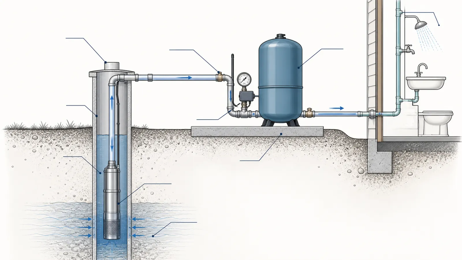
For a submersible pump, also ask whether the proposal covers only the surface line or includes the drop pipe from the pump to the well seal. A Florida Plumbing Code provision indexed by ICC says that, in that jurisdictional text, submersible-pump pipe size is equal to the pump discharge, while other pump piping follows the manufacturer’s specifications and the pressure-tank offset uses friction-loss charts for the material. That is a useful example of how a rule can distinguish components; it is not a national rule. Read the ICC Florida code text and verify the edition currently adopted where the work will occur.
2. Collect the evidence before comparing sizes #
The worksheet below is the minimum useful handoff. A homeowner can fill the observation and document fields without opening a control box or disturbing a pressurized fitting.
| Input | Record this | Why it changes the decision |
|---|---|---|
| Pump type | Submersible, shallow-well jet, deep-well jet, constant-pressure/variable-speed, or unknown | Suction, discharge, controls, and installation rules differ |
| Exact pump model | Photograph the nameplate from a safe, dry location; include horsepower only as a secondary detail | The pump curve and connection requirements are model-specific |
| Pump discharge connection | Nominal port size, thread or fitting type, and where the measurement was taken | This establishes the manufacturer minimum, if the manual gives one |
| Proposed pipe | Nominal size, material, schedule or SDR, and manufacturer-listed inside diameter | Friction depends on the actual bore and surface, not the label alone |
| Design flow | GPM required or measured, plus whether irrigation or simultaneous fixtures are included | Higher flow raises velocity and friction loss |
| Developed length | Centerline distance through every straight segment, not a rough map distance | Friction accumulates with length |
| Elevation | Vertical rise from the pump discharge reference to the tank connection and, separately, to the highest fixture | Elevation consumes pressure even if the pipe is large |
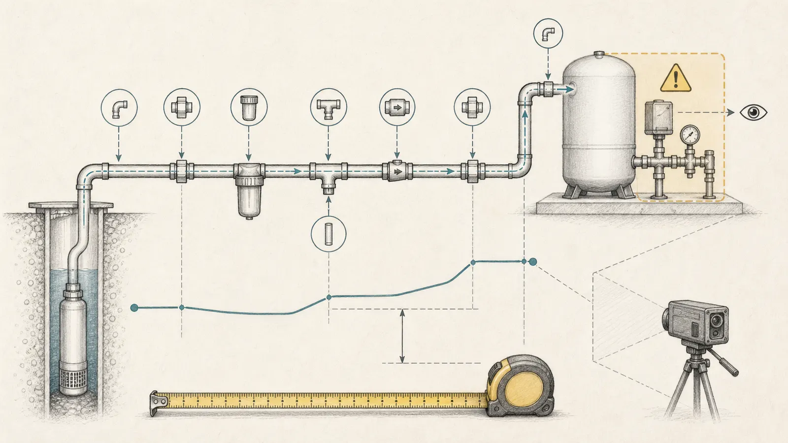
| Fittings and restrictions | Elbows, tees, check valves, unions, filters, meters, reducers, partially closed valves, and treatment equipment | Each can add local loss; valves and fittings can be important contributors |
| Pressure settings | Cut-in, cut-out, tank pre-charge, and any constant-pressure target | The pump must reach the required operating pressure at the actual flow |
| Well supply | Static level, pumping/dynamic level, measured yield, and date/season of the test | A bigger pipe cannot compensate for a source that cannot sustain the demand |
| Local requirement | State, county, city, health department, permit, or water district rule and edition | A manufacturer manual does not replace an adopted code or permit condition |
Grundfos frames domestic groundwater pump sizing around required flow and total head. Its guidance includes the dynamic water level while the pump is operating, the loss and head to the diaphragm tank, the loss to the highest tap, and the minimum pressure at that tap. Grundfos’ domestic groundwater sizing lesson is not a substitute for the exact pump curve, but it is a good test of whether a proposal has enough inputs.
Take photographs of labels, exposed pipe, the pressure gauge, and accessible fittings. Do not remove covers to photograph wiring. Measure the exposed run with a tape only where the route is accessible and safe. For buried pipe, ask for the installer’s as-built route, permit drawing, or a measured estimate with the uncertainty stated. Do not present an estimate as a measured length.
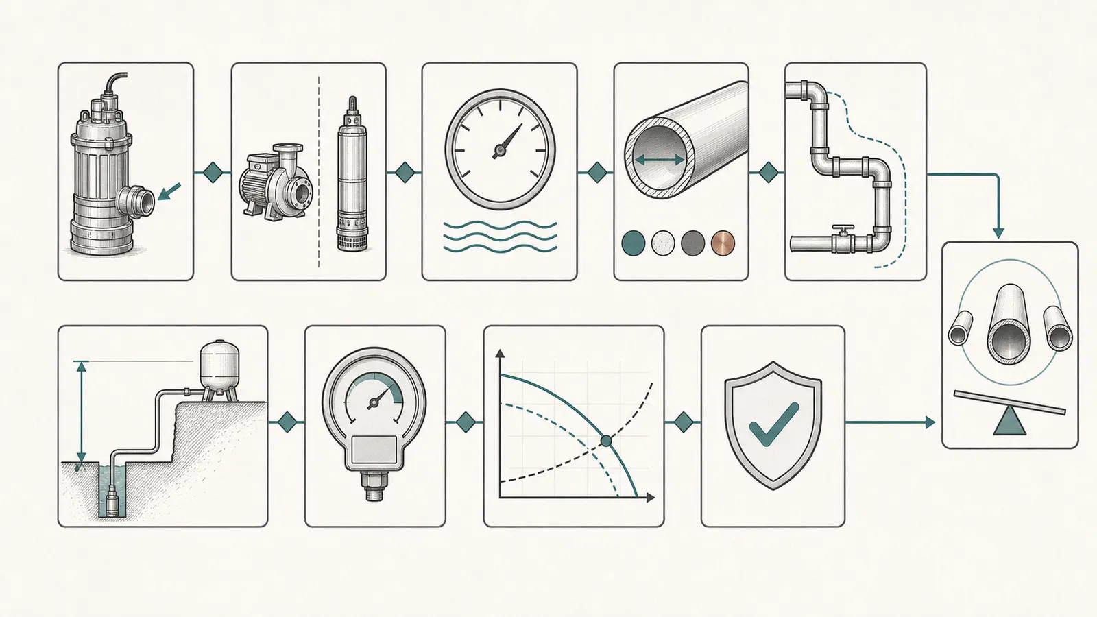
3. Calculate the hydraulic question, not just the nominal size #
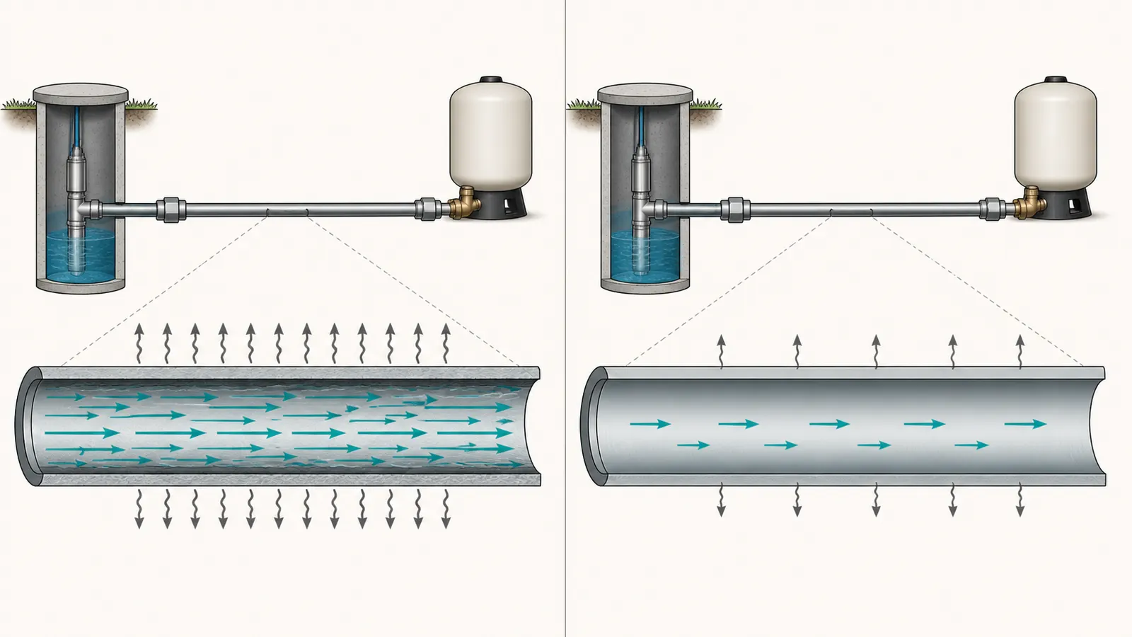
Pipe sizing is a pressure-and-flow comparison. In plain language, the pump must provide enough head to overcome the lift, the desired pressure, and the losses in the pipe and fittings at the design flow. Grundfos explains that flow, head, and power are related; friction loss occurs in the pipe, elbows, and valves; and increasing diameter reduces velocity and friction loss. Grundfos’ basic hydraulics explanation supports the direction of the decision, but the actual number must come from a chart or calculation for the selected material and inside diameter.
A screening equation is:
Required pump head at design flow
= dynamic lift to the tank
  + pressure head required at the tank or control point
  + friction loss in straight pipe
  + equivalent loss from fittings, valves, and equipment
For a domestic pressure system, the pump curve must then be checked at that required head and flow. A pump that can produce 10 GPM at a low head may produce substantially less at the head created by a deep water level, uphill tank location, pressure setting, and long line. Horsepower alone cannot establish the operating point.
A bounded pipe-only example
Suppose a proposed surface run carries 10 GPM through 120 feet of Schedule 40 PVC. A Grundfos SQ handbook friction table lists approximately 6.3 feet of head loss per 100 feet for 1-inch Schedule 40 PVC at 10 GPM and approximately 1.7 feet per 100 feet for 1-1/4-inch Schedule 40 PVC at the same flow. See the manufacturer’s friction-loss table.
The straight-pipe portion of the screening comparison is:
| Proposed pipe | Table loss at 10 GPM | Calculation for 120 ft | Straight-pipe loss |
|---|---|---|---|
| 1-inch Schedule 40 PVC | 6.3 ft per 100 ft | 6.3 × 1.2 | 7.56 ft of head |
| 1-1/4-inch Schedule 40 PVC | 1.7 ft per 100 ft | 1.7 × 1.2 | 2.04 ft of head |
The larger line saves about 5.5 feet of straight-pipe head in this narrowly defined example. That difference can matter when the pump is close to its pressure-switch cut-out or when a long run has several fittings. It does not prove that either pipe is acceptable, because the example excludes elbows, tees, check valves, filters, reducers, elevation, the drop pipe, the well’s dynamic water level, and the pump curve. It also assumes the table’s material and inside-diameter conditions match the proposed product.
This is why “bigger is better” is incomplete. Upsizing can lower friction and make more of the pump’s head available at the tank. It can also add cost, require transition fittings, and still fail to solve a wrong pump selection, inadequate well yield, blocked filter, leaking check valve, or insufficient pressure-control design. The correct comparison is the smallest permitted option that leaves a documented pressure and flow margin for the actual system—not the smallest nominal label someone remembers.
Treat fittings as part of the pipe
Count fittings from the pump discharge reference to the tank connection. Include a check valve even if it is hidden in a well component or pump assembly, and identify filters, softeners, meters, pressure-reducing devices, and narrow flexible connectors. Washington State Department of Health describes friction head as the sum of losses through piping, valves, and fittings and notes that fittings and valves can contribute materially to system friction. Its flow examples are for Group B water-system design, not a private-well residential code, but the measurement lesson transfers: a straight-length-only estimate can understate loss. Review the Washington DOH guidance.
If the proposal says “the fittings don’t matter,” ask for the calculation basis. The answer may be that the run is short and the losses are negligible relative to pump head. That can be reasonable. It is different from omitting fittings without checking them.
4. Check the pump type, well yield, and pressure settings #
The same pipe label can have different consequences depending on the pump arrangement.
Submersible pump
A submersible pump pushes water up the drop pipe. The surface discharge-to-tank line begins after the wellhead or first accessible fitting, but the total pump duty includes the water level in the well, the drop pipe, surface piping, elevation, pressure requirement, and losses. Capture the pump model, set depth, well diameter, static water level, pumping or dynamic water level, and any available well-test result.
The dynamic water level matters more than the static level while the pump is operating. Grundfos specifically tells the designer to use the water level when the pump is in operation and to select the pump from the desired flow and head on its curve. Use the Grundfos groundwater sizing guidance as the model for the input list.
Shallow-well or deep-well jet pump
A jet pump has suction-side concerns that a submersible system does not. The Sta-Rite manual says suction pipe should be at least as large as the suction port in its installation instructions, calls for few fittings, and requires joints to be air- and water-tight because an air leak can prevent the pump from pulling water. Its discharge-to-tank instruction is separate and again uses the discharge-port minimum. Pentair’s manual shows both sides of the arrangement.
Do not use a surface jet-pump rule to size a submersible drop pipe, and do not infer from a large suction pipe that the discharge line can be reduced. The exact manual controls the connection details.
Constant-pressure or variable-speed system
A drive-controlled pump may not operate like a simple 30/50 or 40/60 pressure-switch system. The controller, pressure sensor, target pressure, minimum flow, bypass, and fault logic can change the relevant operating points. Photograph the model and error code from the outside, then use the manufacturer’s manual. Do not adjust a drive or pressure setting because a nominal pipe size seems too small.
Pressure-switch settings and tank connection
Record cut-in and cut-out from the gauge only if the gauge can be observed safely and the readings are stable. Record the tank pre-charge from service paperwork if available; do not remove a valve cap or bleed a tank unless the exact tank procedure is known and the system has been made safe. Pentair’s listed jet-pump manual gives a specific example in which pre-charge is set 2 PSI below the cut-in with the tank at zero water pressure, but that is an equipment instruction, not permission to apply the number to every tank or setting. Read the manufacturer’s tank procedure.
The pipe must let the pump reach the pressure required by the control without excessive loss. If the pump stalls just below cut-out, a larger pipe may help only if friction loss is a meaningful part of the missing head. If the pump cannot reach cut-out because the well level has fallen, the pump is worn, the motor is under-voltage, a valve is closed, or the system has a leak, upsizing the pipe will not cure the cause.
Penn State Extension defines well yield as the maximum rate at which a well can be pumped without lowering the water level below the pump intake. It notes that low-yield wells may need storage when peak demand exceeds the source flow. See Penn State’s water-system planning guidance. A larger pipe cannot increase that yield; it can only reduce loss between the water the pump can obtain and the tank.
5. Use the accept, upsize, or stop decision #
Use this matrix to compare a written proposal. “Accept” means the evidence is complete enough for a reasonable comparison, not that the homeowner is being asked to install the pipe personally.
| Decision | Evidence pattern | Safest next action |
|---|---|---|
| Accept the proposed size for further review | Exact pump manual identified; pump port and proposed pipe are compatible; material and inside diameter are known; flow, developed length, fittings, elevation, settings, and pump curve are addressed; local requirement is checked | Ask for the calculation or chart page and keep it with the quote |
| Consider upsizing | The proposed pipe is permitted but has appreciable friction at the design flow; the run is long; elevation or fittings consume much of the available head; the pump curve has limited margin | Ask the designer to recalculate the larger option and show pressure at the tank and highest fixture |
| Stop and request a documented calculation | Pump model or type is unknown; flow is guessed; dynamic water level is missing; buried length is unverified; the quote treats the service line as the pump-to-tank line; code or manual requirements conflict | Do not accept a universal size claim; request a site-specific hydraulic and installation explanation |
| Stop and investigate the source or pump | The system is losing pressure, running dry, producing air or sediment, or cannot reach its existing cut-out; well yield and pumping level are unknown | Have a qualified well professional test flow, pressure, water levels, and equipment before changing pipe size |
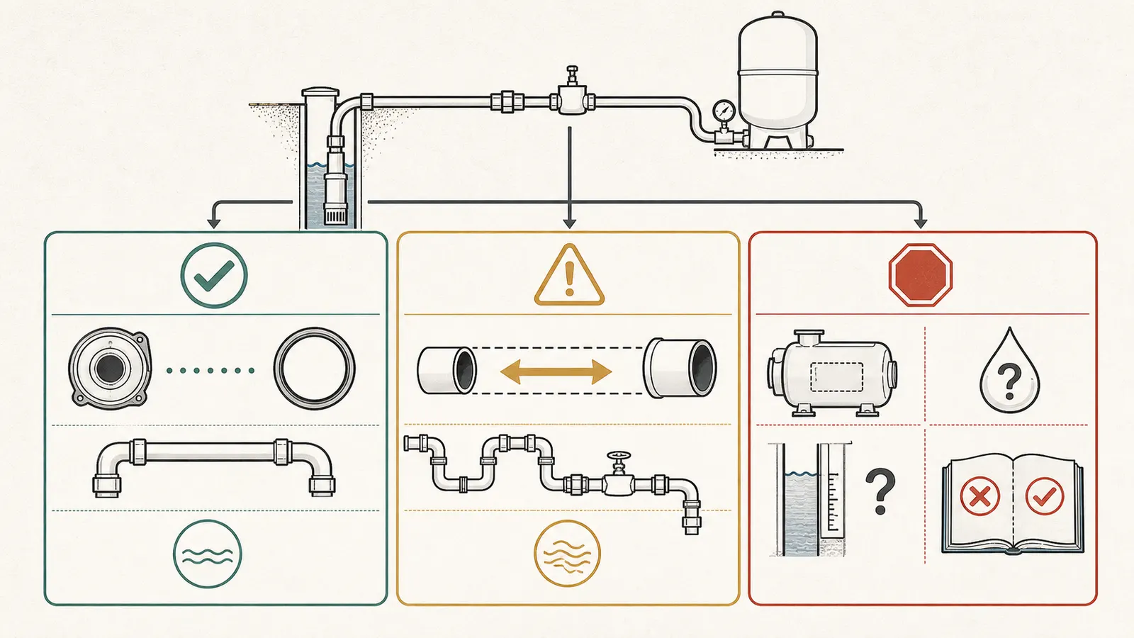
What a defensible proposal should show
Ask for these items in writing:
- The exact pump brand, model, type, discharge connection, and manual revision used.
- The selected pipe’s nominal size, material, schedule or SDR, and inside diameter.
- Design flow in GPM and what simultaneous demand it represents.
- Developed length and the method used to account for elbows, tees, valves, check valves, filters, and reducers.
- Elevation change from the pump discharge reference to the tank connection and to the highest fixture, if the quote includes the house system.
- Cut-in and cut-out settings, tank pre-charge assumption, and required pressure at the tank or highest fixture.
- Pump-curve point showing expected flow and head at the proposed operating condition.
- Well static level, pumping level, yield, and the date or conditions of those measurements when source capacity affects the decision.
- The current local permit or code requirement and the official source used to verify it.
Read the proposal as an evidence chain
A good proposal should let you follow one line of reasoning from the source to the fixture. Start with the required household flow, then ask where that flow is measured or estimated. Follow it through the pump curve to the pressure and head the pump must deliver. Then follow the head budget through the well’s dynamic level, the drop pipe, the surface run, the tank connection, and the service line if that line is included. The pressure that remains at the tank and highest fixture should be visible in the calculation.
This sequence catches several common category errors:
- A contractor may quote the pump’s maximum flow as though it were the required household flow. Maximum flow from a curve is not automatically the design demand.
- A homeowner may provide the distance from the well house to the home when the quote is actually sizing the short pump-to-tank connection. The endpoints must be named.
- A proposal may use nominal pipe size while the friction chart uses a different inside diameter. Ask the proposer to identify the product and chart row.
- A pressure-switch setting may be raised to compensate for an unexamined restriction. That increases the pump’s required head; it does not prove the restriction is gone.
- A larger pipe may be offered for a well that is losing water level during demand. That is a source-capacity issue, not a pipe-friction conclusion.
You do not need to reproduce a professional hydraulic model to spot these gaps. You need the assumptions, the endpoints, the selected chart or calculation method, and the resulting pressure and flow. If a result depends on an unknown, the proposal should say so and identify the measurement needed to resolve it. A range can be honest; a single precise pipe size built on guessed inputs is not necessarily more reliable.
If the proposal has only “1-inch PVC from pump to tank” and a price, it is not yet an evidence-backed sizing decision. It may turn out to be correct. The missing evidence is the problem.
6. Know when upsizing cannot solve the real problem #
Upsizing is a hydraulic remedy for friction loss. It is not a remedy for every low-pressure or long-run symptom.
| Observation | What it may support | What it does not prove |
|---|---|---|
| Pressure falls more than expected only during high flow | Pipe or fitting loss, restricted filter, inadequate pump head, or demand above design flow | That the well is low-yield or that the pipe is the only fault |
| Pump runs but pressure stops below cut-out | Leak, restriction, wrong setting, worn pump, low voltage, low water level, or excessive system head | That a larger pipe will restore shutoff |
| Water level falls toward the pump intake during demand | Source limitation or overpumping | That a larger pressure tank or line will create more groundwater |
| Air or sediment appears during extended pumping | Low pumping level, suction issue on a jet pump, disturbed well, or damaged submerged components | That the pump model or pipe size is wrong |
| Pressure is fine at the tank but weak at the home | Household service-line friction, elevation, treatment restriction, gauge location, or a house-side problem | That the pump-to-tank pipe should be upsized |
Penn State’s low-yield-well guidance says a pressure tank has limited usable storage and that a larger pressure tank alone is not enough to solve a low-yield problem; an intermediate storage arrangement may be considered when source flow is inadequate. Read the low-yield-well explanation. That is the important boundary for this decision surface: do not spend on a larger line as a substitute for a source-capacity diagnosis.
If the system has changed recently, document the change before redesigning the pipe. Examples include a new irrigation zone, treatment backwash, a filter replacement, a pressure-switch adjustment, a well-service visit, drought, flooding, a new building, or a pump replacement. A sudden symptom after one of those events raises the value of checking restrictions, settings, connections, and water level before assuming the original pipe was undersized.
7. Apply local rules and hand off safely #
Manufacturer instructions, code, and hydraulic design each answer a different question. The manufacturer tells you how the listed equipment may be connected. A code tells you what the adopted jurisdiction requires. The hydraulic calculation tells you whether the proposed configuration can deliver the intended flow and pressure. None of those automatically replaces the others.
The ICC-hosted Florida text is a helpful example because it separates submersible pump discharge sizing, other pump manufacturer instructions, and pressure-tank offset friction charts. But the page is identified as the 2010 Florida Plumbing Code. The Florida Building Commission now lists the 9th Edition (2026) Florida Building Code and current supplements on its code-resources page. That change is a direct warning against quoting an old excerpt as a current national rule. Check the Florida Building Commission’s current resource index, then ask the authority having jurisdiction which edition and amendments apply at the property. In another state, use that state, county, city, health department, or water-district source instead.
Keep pipe sizing separate from water quality
Pipe sizing cannot diagnose potability or water quality. Stop using the well water for drinking and cooking, and use a known-safe alternative, if there is an unusual odor, color, or taste; a positive or unknown water test; flooding; or suspected contamination. CDC guidance treats a change in taste, color, or smell and flooding near a private well as reasons to test, while EPA says to contact the local or state health department or environmental agency after suspected flood contamination and not to drink from a flooded well. Review the CDC well-testing guidance and EPA’s private-well safety guidance. Contact the local health authority or a qualified well professional for testing and treatment guidance before resuming drinking or cooking use. A larger pipe, a new pressure setting, or a friction-loss calculation is not water treatment.
Homeowner-safe information gathering
Safe observations can include:
- Photographing model labels, exposed piping, the pressure gauge, and accessible valves from a dry location without removing covers.
- Recording the gauge reading while a normal fixture runs, if the gauge and fixture can be observed without touching equipment.
- Measuring accessible pipe length and counting visible fittings.
- Recording recent changes, symptoms, run duration, and whether irrigation or treatment equipment was operating.
- Collecting the well log, pump invoice, prior pump curve, permit, service records, and any well-yield or water-level test.
Do not open energized controls, test live wiring, bypass a low-water or pressure safety device, pull a pump, open a well, enter a confined space, or manipulate pressurized equipment for this comparison. Do not run a pump against a closed discharge, run it dry, repeatedly reset a tripped control, or raise the pressure-switch setting to force a result. Pentair’s manual warns that pressure must be released before work on system components and power must be disconnected before work on the pump, motor, or tank. Follow the manual’s safety warnings.
Stop and seek qualified help if there is sparking, a burning odor, hot or wet electrical equipment, uncontrolled pressure, no water while the pump runs, sudden air or sediment, an unknown buried route, or a need to access the well or controls. A qualified well professional or plumber can measure flow and pressure; a qualified electrician should handle electrical testing. Ask the professional to record the pump model, operating point, water levels, pressure settings, pipe and fittings, and the calculation used. Those records are more valuable than a nominal size written without context.
Verify the decision after work
The handoff should end with an operating record, not only an invoice. Ask the installer to identify the installed pipe material and size, the accessible connection points, the pump model, the pressure-switch settings, and any check valve or filter included in the path. If the line was upsized, ask which friction-loss assumption made the change worthwhile. If the line was not upsized, ask where the available head margin appears in the calculation.
Under normal, defined household demand, the professional can record the pressure at the tank, the observed flow, the pump start and stop behavior, and any available controller information. The homeowner can keep that record with the well log and future service paperwork. If the system is a conventional pressure-switch arrangement, the normal pressure range and cycle behavior are useful baselines. If it is variable-speed, keep the controller target and fault history instead of assuming a 30/50 or 40/60 pattern.
Do not turn verification into an experiment that risks the equipment. Do not close the discharge to force a pressure reading, intentionally run multiple fixtures until the well runs dry, defeat low-water protection, or ask an unqualified person to measure energized circuits. A qualified professional should choose the test condition and stop it if the well level, pressure, temperature, or equipment behavior becomes unsafe. The goal is to confirm that the documented design point is plausible—not to discover the system’s failure limit.
The homeowner decision is therefore straightforward even when the engineering is not: accept a proposed size only when it starts at the actual pump connection and shows its hydraulic and local-rule checks; consider upsizing when the calculation shows meaningful friction loss and the pump has the head to benefit; stop when key inputs are missing or the problem may be well yield, pump condition, controls, or a restriction. That is the difference between comparing a pipe size and guessing at one.
Cite this guide
Brictale. “What Size Pipe From a Well Pump to a Pressure Tank?.” Published 2026-09-07; updated 2026-09-07.
https://brictale.com/water/pumps/well-pump-to-pressure-tank-pipe-size · Read the Markdown version
Sources and scope
Evidence behind this page
- Pentair’s Sta-Rite shallow-well jet-pump manual says the pipe connected to the pump discharge port for a pressure tank must be at least as large as the discharge port.
Pentair — Sta-Rite Shallow Well Jet Pumps Owner’s Manual
Manufacturer instruction for the listed Sta-Rite SN/HN shallow-well jet-pump configurations; not a universal rule for every pump type, model, material, or jurisdiction.
Accessed · Link to this claim - The same Pentair manual distinguishes the pump discharge-to-tank connection from the household plumbing connection and calls for two tees in the pre-charged-tank arrangement or a tee and tank connection in the standard arrangement.
Pentair — Sta-Rite Shallow Well Jet Pumps Owner’s Manual
Illustrated connection layouts and instructions in the listed manufacturer manual; fittings and arrangement vary by equipment.
Accessed · Link to this claim - Grundfos identifies required flow, dynamic water level, head and loss to the diaphragm tank, loss from the tank to the highest tap, and minimum pressure at that tap as pump-sizing inputs.
Grundfos — Pump Sizing and Installation in Domestic Groundwater Applications
Grundfos educational guidance for domestic groundwater submersible-pump sizing; the example and equipment assumptions are not a site-specific design.
Accessed · Link to this claim - Grundfos explains that friction loss occurs in pipe, elbows, and valves and depends on flow, pipe length, pipe surface, and velocity; increasing diameter reduces velocity and friction loss.
General hydraulic education from the manufacturer; actual losses require the selected material, inside diameter, flow, length, and fitting data.
Accessed · Link to this claim - Penn State Extension defines well yield as the maximum pumping rate that does not lower the water level below the pump intake and says a low-yield well may need storage when peak demand exceeds source flow.
Penn State Extension — Water System Planning: Estimating Water Needs
Pennsylvania State University Extension planning guidance; example minimum flows and tables are planning references, not a national code or a guarantee of any individual well.
Accessed · Link to this claim - Penn State Extension explains that pressure-tank storage is limited and that adding a larger pressure tank alone is not enough to solve a low-yield well problem; intermediate storage may be appropriate.
Penn State Extension — Using Low-Yielding Wells
Pennsylvania State University Extension guidance for low-yield private wells; the system arrangement and costs described there are not a universal design recommendation.
Accessed · Link to this claim - A Florida Plumbing Code pump provision indexed by ICC states that submersible-pump pipe size is equal to the pump discharge, other pump piping follows the manufacturer’s specifications, and pressure-tank offsets use friction-loss charts for the material.
ICC — 2010 Florida Plumbing Code, Chapter 6 Water Supply and Distribution
Florida Plumbing Code text identified as 2010 in the ICC resource; jurisdiction- and edition-specific example only. The currently adopted local code and amendments control.
Accessed · Link to this claim - The Florida Building Commission’s current code-resources page lists the 9th Edition (2026) Florida Building Code and current supplements, demonstrating why an older code excerpt cannot be treated as the homeowner’s current local rule.
Florida Building Commission — Code Resources
Florida statewide code-resource index; it does not determine the code adopted in another state, county, city, or special district.
Accessed · Link to this claim - Pentair warns that pressure must be released before working on system components and that power must be disconnected before working on the pump, motor, or tank; it also calls for local-code-compliant wiring.
Pentair — Sta-Rite Shallow Well Jet Pumps Owner’s Manual
Safety instructions for the listed pump family; a homeowner should not generalize the manual into permission to service other equipment.
Accessed · Link to this claim - Washington State Department of Health describes friction head as the sum of losses through piping, valves, and fittings and notes that fittings and valves can contribute materially to system friction.
Washington State Department of Health — Group B Water System Design Guidelines
Washington Group B public-water-system design guidance; its flow examples and allowances are not a residential private-well code requirement.
Accessed · Link to this claim - Grundfos’ SQ handbook friction table gives different friction-loss values for different Schedule 40 PVC inside diameters at the same flow, illustrating why a size comparison must use the material and actual inside diameter.
Manufacturer table for the listed Grundfos SQ product handbook and Schedule 40 PVC assumptions; use the applicable chart for the actual pipe product and hydraulic design.
Accessed · Link to this claim - CDC advises testing private well water when its taste, color, or smell changes and after flooding or other nearby problems, and directs owners to health departments or certified laboratories for testing guidance.
CDC — Guidelines for Testing Well Water
Public-health guidance for private well owners; it supports a conservative stop-and-test boundary, not a diagnosis of any particular water-quality event.
Accessed · Link to this claim - EPA says that suspected private-well contamination after flooding requires contacting the local or state health department or environmental agency for inspection and testing advice, and says not to drink from a flooded well.
EPA — Protect Your Home’s Water
EPA private-well safety guidance for flooding and suspected contamination; local health authority instructions and test results control the site-specific response.
Accessed · Link to this claim