Private Well Pump TDH Calculator: Check a Replacement Proposal
Calculate a private-well pump's total dynamic head from pumping level, flow, pressure, elevation, pipe friction, and treatment loss—without guessing missing inputs.
The short answer
TDH is the pumping water level lift plus elevation, required pressure converted at 2.31 feet per psi, pipe and fitting friction, and treatment loss at the design flow. Use a pumping level—not total drilled depth or horsepower—and leave friction or well-performance values unknown when the records do not support them.Private Well Pump TDH Calculator: Check a Replacement Proposal
For a private-well replacement, calculate the duty point as:
TDH = pumping-water-level lift + elevation + pressure head + pipe/fitting friction + treatment loss
Convert required pressure to head with pressure head = psi × 2.31. Use the water level while the pump is delivering the design flow—not total drilled depth, not a stale static level, and not horsepower—as the lift input. NC State Extension’s pump-sizing guidance defines total dynamic head from pressure, elevation, and friction terms, while Franklin Water’s pump-testing guidance distinguishes static water level from the deeper pumping level reached under flow.
This worksheet gives you three honest outputs:
- a known-base TDH from supported lift, elevation, pressure, and documented treatment loss;
- a design TDH range when pumping level, pressure requirement, or friction has a documented low and high value; and
- an evidence gap when an input is missing.
It does not select a pump, certify a well yield, predict runtime, or approve an installation. A pump proposal is credible only when its flow requirement and TDH duty point can be traced to records, measurements, product literature, and the correct manufacturer performance curve.
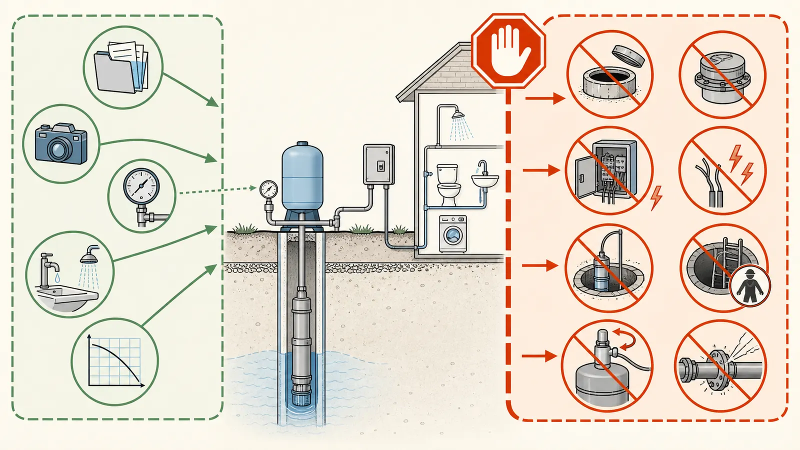
Safety boundary: Use this page for record review and observation. Do not open or remove a well cap, open energized controls, test live wiring, pull a pump, enter a well pit or confined space, change pressure-switch settings, or disconnect pressurized piping to fill in a blank. Those tasks belong to a qualified well or pump professional. If the pump intake, pumping level, system pressure, or pipe route is unknown, leave it unknown and request the missing evidence.
1. What the TDH number means for a homeowner #
TDH is the head, expressed in feet of water, that the pump must overcome at a stated flow. It is a system requirement, not a property of the pump alone. A replacement pump can have the same horsepower as the old one and still be wrong if the required flow, water level, pressure, pipe route, treatment equipment, or elevation has changed.
The terms answer different questions:
| Term | What it represents | The homeowner question it answers | What it cannot prove |
|---|---|---|---|
| Total drilled depth | Depth from the chosen well reference point to the reported bottom | How deep is the drilled hole? | The lift the pump sees or the well’s sustainable yield |
| Static water level | Water depth after the well has rested, with no active production | Where is the water surface before pumping? | The water surface while the pump is delivering the design flow |
| Pumping water level | Water depth while the well is producing at the stated flow | How far must the pump lift water at the duty point? | A universal level for every flow, season, or drought condition |
| Elevation head | Vertical change from the same wellhead datum used for PWL to the delivery point | How much higher or lower is the outlet or tank? | Pipe losses along the route |
| Pressure head | Required residual pressure converted from psi to feet | How much pressure must remain at the delivery point? | Flow capacity or well yield |
| Friction and treatment loss | Energy lost through pipe, fittings, valves, filters, softeners, and similar equipment | What does the route consume at the design flow? | A value when route, flow, or product data are missing |
Washington State Department of Health's Guidelines for Group B Public Water System Approval express total operating head as pumping-level lift to the wellhead, system elevation to the delivery point, friction loss, and residual pressure head. That document applies to Washington Group B water-system approval, not to every U.S. private well, but its explicit head table is useful for auditing a residential proposal.
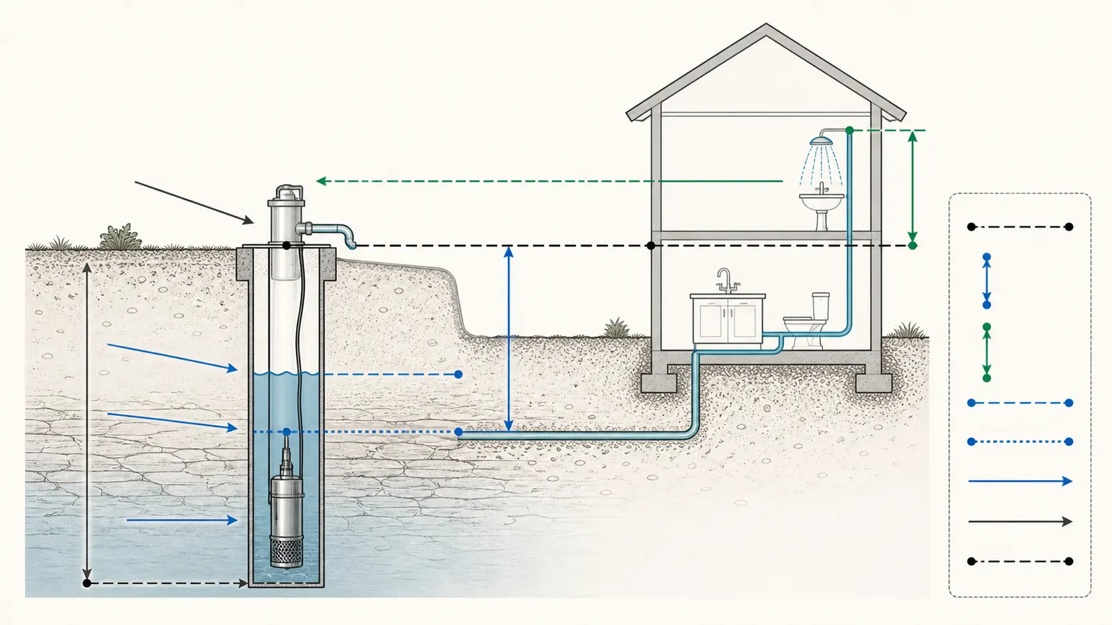
The most common homeowner error is putting total well depth into the lift term. Suppose a record says the well is 420 feet deep, but a professional measurement shows the pumping level is 185 feet below the wellhead while delivering 8 gallons per minute. The pump’s operating lift begins with the 185-foot pumping level, not 420 feet. The total depth may still matter for well construction, pump setting, or a professional’s well assessment; it is not a substitute for the hydraulic operating level.
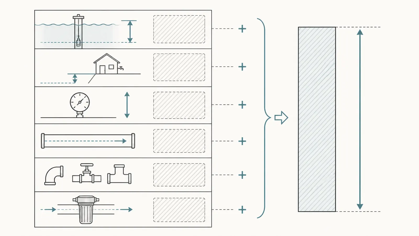
The second common error is using static level as though it were pumping level. Static level is useful context and a starting point for drawdown. It is not the level that exists after the pump has lowered the water surface at the design flow. A proposal that says only “static water level: 90 feet” has not yet shown the lift at 8 or 10 gpm.
The third is treating a pump’s horsepower as its output. Horsepower describes motor capacity under a particular pump assembly and electrical configuration. The useful question is whether the exact pump, speed, impeller or stage configuration, and voltage produce the required flow at the calculated TDH. NC State Extension explains that the pump curve shows the flow available at a given head and that the target flow/head point must lie on or below the curve.
2. Separate total depth, static level, and pumping level #
The three depths to put in separate boxes
Use one fixed reference point for every depth, normally a documented point on the well casing or wellhead. Record the date, unit, and whether the value came from a well record, a current professional measurement, or an installer’s proposal.
| Input | Definition for this worksheet | Acceptable evidence | Do not substitute |
|---|---|---|---|
| Total drilled depth | Depth to the reported or measured bottom of the well | Completion record or professional measurement | Pumping level |
| Static water level (SWL) | Water depth after the well has recovered and is not producing | Dated level measurement with rest condition | Pressure-gauge reading or recovering level |
| Pumping water level (PWL) | Water depth at a stated flow and test condition | Pumping-test report or professional measurement | Static level or total depth |
| Pump intake or setting | Depth of the pump intake or an agreed operating boundary | Installation record or professional confirmation | Total depth |
| Reference point | Exact datum from which each depth was measured | Record or field note | “Ground level” when the record used casing top |
For this worksheet, use the documented wellhead or casing-top point as the single geometry datum. PWL is the vertical distance downward from that datum to the water surface while the pump delivers the stated flow. E is the vertical change from that same datum to the controlling delivery point: positive when the outlet is higher and negative when it is lower. The pump intake or setting remains a separate installation record; do not start E at the pump intake when PWL is already measured from the wellhead, because that can double-count or omit the vertical geometry. This convention follows the Washington DOH well-pump table, which lists distance from pumping level to wellhead separately from elevation difference from wellhead to delivery.
Franklin Water defines static water level as the natural level when the well is not producing and pumping water level as the lower level reached while pumping until inflow and pumped flow balance. That manufacturer guidance describes a controlled pumping-test context; it does not tell a homeowner to perform an improvised test at a wellhead.
If a professional report gives a static level of 78 feet and drawdown of 32 feet at 8 gpm, the corresponding pumping level is:
PWL = SWL + drawdown = 78 ft + 32 ft = 110 ft below the reference point
That 110-foot value is specific to the stated 8-gpm test conditions. If your proposal calls for 12 gpm, do not carry 110 feet forward as a universal truth. Ask whether the professional has a pumping level or well-performance result at the proposed flow, or ask the professional to state the design assumption.
Why total depth can look persuasive and still be wrong
A generic calculator may ask for “well depth” because it is easy to find on a completion record. That shortcut can overstate or understate the hydraulic lift depending on the water level and where the pump is installed. Berkeley Lab’s well-pump energy documentation acknowledges that practical dynamic head depends on depth to water and piping friction, but its simplified energy model uses well depth and ignores friction under an assumption that the terms approximately cancel. That may be acceptable for a national energy model; it is not enough evidence for a site-specific replacement proposal.
Keep the total depth in the evidence sheet, but label it “construction context.” Use PWL for the duty-point calculation. If PWL is unknown, the result should say TDH incomplete: pumping level not established, not silently reuse total depth.
A current level and an old record answer different questions
An old well record may contain a static level measured when the well was drilled. It can establish historical context, but it does not establish today’s pumping level. A current static measurement can show present conditions, but it cannot reveal the pump intake or drawdown at the proposed flow.
Ask for a professional report that identifies:
- the fixed reference point;
- the date and time;
- whether the level is static, pumping, or recovering;
- the pump or flow condition during the reading;
- the rest or recovery condition before a static reading;
- the measurement method and supported precision; and
- any obstruction, sediment, oil, access limitation, or unusual water-use condition.
Do not improve a weak record by averaging incompatible numbers. A 90-foot static level measured from casing top and a 110-foot pumping level measured from grade are not ready to subtract until the datum difference is known.
3. Collect the inputs without inventing friction or well performance #
Build the worksheet before comparing pumps. The source column matters as much as the number column.
| Required input | Unit | What to ask for | If unknown |
|---|---|---|---|
| Design flow | gpm | Maximum simultaneous residential demand or documented required flow | Do not infer it from horsepower |
| Pumping water level | ft below reference | PWL at the design flow, or a stated range | Report TDH incomplete or as a range only if bounded |
| Delivery elevation | ft | Vertical change from the same wellhead/casing datum used for PWL to the highest or controlling outlet; positive upward | Measure or have a professional survey it |
| Required residual pressure | psi | Pressure required at the delivery point while flowing | Do not assume cut-out pressure equals fixture pressure |
| Pressure-switch setpoints (context only) | psi | Cut-in and cut-out from installation or service documentation, or a qualified professional's observation of a normal cycle | Do not infer a setpoint from a gauge; do not change the switch |
| Visible gauge observation (separate) | psi | Current pressure reading, with pump and flow state recorded, from a gauge that is already visible | It is not a switch setpoint or required residual pressure |
| Straight pipe | ft | Actual route length, inside diameter, material, and flow direction | Leave friction unknown |
| Fittings and valves | count/type | Elbows, tees, check valves, restrictions, backflow devices, and control valves | Leave the allowance unknown |
| Treatment loss | ft or psi | Filter, softener, UV, iron treatment, or other device loss at design flow | Use the product manual or professional test |
| Pump curve | ft at gpm | Exact model, speed, configuration, voltage, and curve | Do not approve from horsepower alone |
| Well performance | gpm and test condition | Yield or drawdown test with date and conditions | Do not invent a yield or runtime |
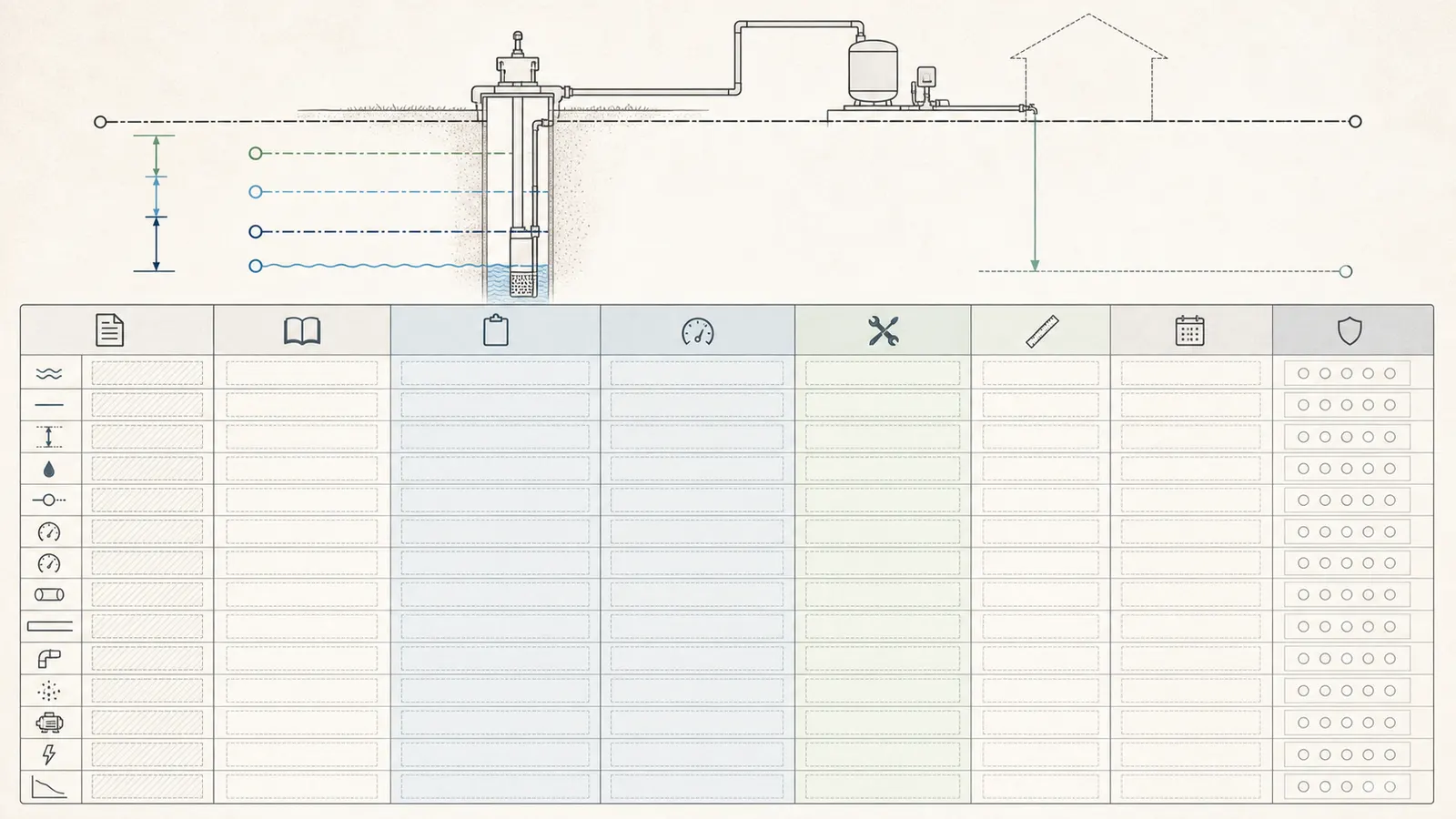
Flow is a design input, not a promise from the well
Define the event the replacement must serve. It might be one shower plus a toilet refill, a shower plus a washing machine, or an irrigation zone that the system is actually intended to run. NC State Extension recommends adding the flows of fixtures that may operate at the same time and using product literature where available.
Write the demand as a scenario:
design flow = simultaneous fixture flow 1 + fixture flow 2 + other required flow
If the proposal says “10 gpm household demand,” ask what was included and whether it is a measured, specified, or assumed number. Do not convert average daily gallons into a peak flow without a stated demand model. Do not use a well-yield number as though it were the pressure-system flow requirement; yield describes what the well can supply under a test, while the duty point describes what the pump must deliver through the system.
Pressure-switch settings are context, not automatic TDH terms
For a conventional pressure-tank system, the switch turns the pump on at cut-in and off at cut-out. NC State Extension describes the pressure switch as engaging the pump when pressure drops and disengaging it when demand ends. Those settings tell you how the control is intended to operate. They do not, by themselves, tell you the pressure at the highest fixture while water is flowing. The fixture also sees elevation, line friction, treatment loss, tank and valve behavior, and possibly pressure variation.
Use documented or professionally observed switch information only as control context:
- Ask the installer what residual pressure must remain at the controlling fixture at the design flow.
- If the proposal is unclear, show separate pressure scenarios using the documented required residual pressure. A cut-in or cut-out value may be shown as a clearly labeled control-setting comparison, but it is not automatically the pressure at the flowing fixture. A current gauge reading is only an observation of system pressure at that moment; it does not establish either switch setpoint or required residual pressure. Do not quietly use a “typical 50 psi” assumption as the homeowner’s requirement.
The Berkeley Lab model uses 50 psi as a typical residential pressurization assumption for energy modeling and converts pressure using 2.31 feet per psi. That documentation explicitly describes a simplified model rather than a site-specific hydraulic calculation. A replacement proposal should show your system’s pressure target and why it was chosen.
Do not invent well yield, recovery, or drawdown
A completion report may list a tested yield, but the date, test method, pumping rate, duration, static level, recovery, and season determine what that number means. A pump nameplate or a bucket test at an indoor faucet does not establish sustainable well yield. If the proposal uses “well produces 12 gpm,” ask for the source and conditions.
The safest notation is:
well yield: unknown — no dated test with conditions supplied
That is a useful result. It tells the installer which question remains open. A TDH calculation can proceed with a documented PWL range even when well yield is not known, but it cannot promise that the well will sustain the proposed flow.
4. Calculate a defensible TDH range #
Use feet of head for the calculation. Keep every term visible so another person can audit the result.
Let:
Q= design flow in gallons per minute;PWL= pumping water level in feet below the well reference point;E= vertical elevation change from the same wellhead/casing datum used for PWL to the controlling delivery point, positive when the delivery point is higher;R= required residual pressure at that point, in psi;Hf= straight-pipe, fitting, valve, and check-valve friction loss atQ, in feet;Ht= treatment-equipment loss atQ, in feet; and2.31= the U.S. customary pressure-to-head conversion used by NC State Extension.
The basic equation is:
TDH(Q) = PWL + E + (R × 2.31) + Hf + Ht
The sign of E must follow the actual geometry. If the delivery point is below the wellhead datum, elevation can reduce the net lift. Do not use pump-intake depth as the start of E when PWL is already referenced to the wellhead. If the proposal has multiple outlets, calculate the controlling path—the path with the greatest required head at its own design flow. Do not add the head for every fixture together; the flows may be simultaneous, but the pump serves a system path and demand scenario.
Use ranges when the evidence supports ranges
If the professional gives a PWL range, pressure requirement range, and treatment-loss range, calculate the endpoints:
TDH lower = PWL lower + E + (R lower × 2.31) + Hf lower + Ht lower
TDH upper = PWL upper + E + (R upper × 2.31) + Hf upper + Ht upper
Only use a term’s lower and upper values when both are supported. If pipe diameter or treatment loss is unknown, do not substitute a national average. Report:
TDH known base = PWL + E + pressure head
TDH additional friction/treatment = unknown
This is more useful than a fabricated range because it identifies exactly what the installer must measure or document.
Illustrative worked example — not a measurement of a real home
Assume a proposal is for 8 gpm. A professional report supplies a PWL range of 150–175 feet below the wellhead at that flow. The controlling fixture is 12 feet above the wellhead reference. The required residual pressure is 40–50 psi. The pipe and fitting calculation gives 18–26 feet of friction at 8 gpm, and the treatment manufacturer gives 6–10 feet of loss at 8 gpm.
| Term | Lower case | Upper case | Evidence status |
|---|---|---|---|
| Pumping water level | 150 ft | 175 ft | professional report at 8 gpm |
| Elevation | 12 ft | 12 ft | stated route measurement |
| Pressure head | 40 × 2.31 = 92.4 ft | 50 × 2.31 = 115.5 ft | documented design pressure range |
| Pipe and fitting friction | 18 ft | 26 ft | route and flow calculation |
| Treatment loss | 6 ft | 10 ft | product literature at 8 gpm |
| TDH | 278.4 ft | 338.5 ft | bounded design range |
The proposal should therefore show a duty point of 8 gpm at roughly 278–339 feet of head, subject to the stated assumptions. That is not a pump recommendation. It is the system requirement to plot against the exact pump curve.
If the proposal instead says “420-foot well, 1 hp pump,” the evidence is incomplete. Total drilled depth is not PWL, horsepower is not a duty point, and friction/treatment loss has not been shown. Ask for a revised proposal with the missing terms.
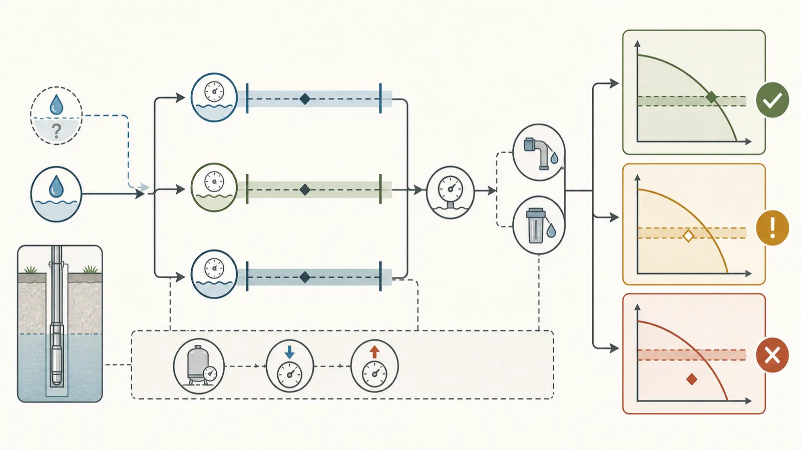
Check the pressure conversion, not just the arithmetic
At 40 psi, pressure head is 92.4 feet. At 50 psi, it is 115.5 feet. A 10-psi change moves the TDH requirement by 23.1 feet before any change in flow or friction. That is why a proposal that simply copies a pressure-switch cut-out value without stating the required residual pressure can be misleading.
5. Handle pipe friction and treatment loss transparently #
Friction is not a universal percentage of well depth. It depends on flow, pipe inside diameter, pipe material and condition, route length, fittings, valves, check valves, and restrictions. NC State Extension explains that friction includes pipe-wall and fitting losses, recommends an equivalent-length method for fittings, and says filtration loss must come from the filter product literature because it varies with filter type and flow.
What a defensible friction line includes
Ask the proposal to identify:
- the design flow used for the friction calculation;
- the actual pipe size and material, not only the connection size;
- the total developed pipe length, including vertical and horizontal runs;
- each material change or restriction;
- fitting and valve counts or equivalent lengths;
- check-valve assumptions;
- the friction source or calculation method; and
- whether the treatment train is included separately.
The straight pipe may be long inside the well and short between the wellhouse and the home, or the reverse. A proposal that lists “10% friction” without flow, pipe, and route evidence is not auditable. Mark it friction allowance unsupported and ask the installer to supply the calculation.
Treatment loss belongs at the design flow
A sediment filter, cartridge filter, softener, iron filter, UV unit, backflow device, or other treatment component can consume head. The loss can change as a filter loads or as flow changes. Use the manufacturer’s pressure-drop table or a professional measurement at the stated flow. If the product literature provides pressure loss in psi, convert it with the same 2.31 factor and keep the original psi value in the worksheet.
Franklin Water notes that adding treatment equipment or water-using components can change surface head conditions and require updated hydraulic calculations. That is a practical proposal check: a pump that worked before a treatment train was added may no longer meet the same duty point.
Do not double-count or hide losses
Ask whether the proposal’s “total head” already includes the drop pipe, pitless adapter, check valve, treatment equipment, and house-side piping. Add each term once. If the installer has rolled them into a single friction number, request the supporting schedule. A single number can be valid, but it must be traceable to the actual system.
If the proposed route or treatment equipment is changing, calculate the existing and proposed configurations separately. A replacement pump proposal that uses the old friction number after a pipe-size change is not a like-for-like comparison.
6. Validate the duty point against the pump curve #
Once the system requirement is calculated, compare the required flow and TDH to the performance curve for the exact proposed pump. Request the curve as a document or manufacturer link that identifies:
- model and pump-end configuration;
- motor horsepower and voltage;
- frequency and speed;
- impeller diameter or stage count when applicable;
- flow axis and head axis units;
- any stated efficiency or operating range; and
- the curve date or catalog revision when the product has variants.
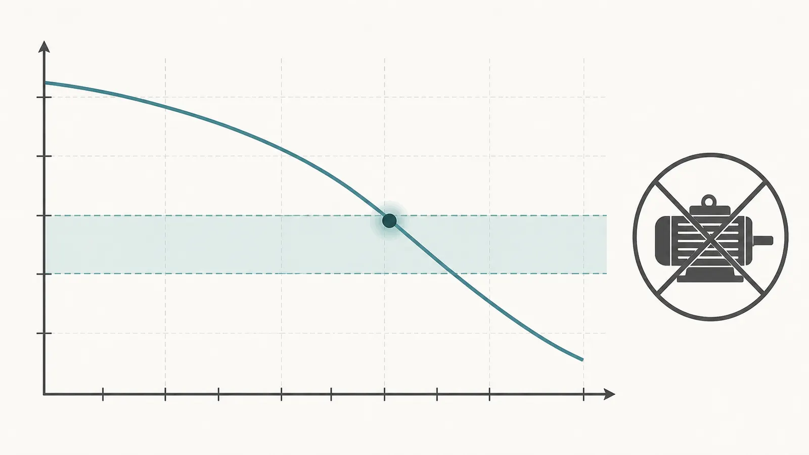
Plot the illustrative duty point at 8 gpm and 278–339 feet of head as a vertical range band. The curve should show what flow that exact configuration produces across that head range. NC State Extension says the target flow/head should be on or below the pump curve and notes that the target discharge should be in the middle third of the curve for overall efficiency.
Treat “meets the head” and “meets the flow at the head” as different statements. A pump may generate high shutoff head but deliver too little flow at the household’s operating head. It may also deliver the flow at low head but fail when the pumping level drops, the pressure target rises, or treatment loss increases.
The proposal comparison table
| Proposal field | Proposal A | Proposal B | Evidence to request |
|---|---|---|---|
| Exact pump model/configuration | Manufacturer model and curve | ||
| Motor hp, voltage, speed | Nameplate and curve match | ||
| Design flow, gpm | Demand scenario or measured requirement | ||
| PWL used, ft | Pumping-level report and flow condition | ||
| Residual pressure, psi | Required pressure at controlling outlet | ||
| Elevation, ft | Wellhead-to-fixture route | ||
| Pipe/fitting friction, ft | Calculation and assumptions | ||
| Treatment loss, ft or psi | Product data at design flow | ||
| TDH lower/upper, ft | Formula with every term visible | ||
| Duty point on curve? | Marked curve, not a horsepower claim | ||
| Well yield evidence | Dated test and conditions | ||
| Low-water protection and controls | Equipment schedule and manual |
If a proposal provides only a pump model and horsepower, ask for the curve and the calculation sheet before deciding. Washington DOH documentation guidance, although written for a different public-system category, illustrates the value of identifying the pump, tank, pipes, valves, gauges, pressure switch, relief valve, and other key components rather than describing a system by motor size alone.
Do not treat a generic model as a private-well specification
Online calculators often use typical depth, typical pressure, or assumed efficiency. Berkeley Lab’s documentation is candid about those simplifications: it uses a national-model default depth, a typical 50-psi pressurization value, and an assumption that ignored friction approximately cancels the difference between well depth and depth to water. Those assumptions are not evidence for your well.
Similarly, an overseas or state-specific technical guide can explain a concept without creating a rule for your property. Ontario’s current equipment-installation guidance describes meaningful differences among centrifugal, jet, submersible, variable-speed, and turbine pumps, including pump-type limits and manufacturer instructions. Its regulatory requirements apply in Ontario, not in the United States. Use it as a reminder to match pump type and installation details to the actual well, then check your state and local requirements with the installer.
7. Interpret the result and flag proposal gaps #
Use the result as a decision surface. The right next step depends on what is known, not just on the number of feet.
| Result or proposal pattern | What it supports | What it does not support | Next action |
|---|---|---|---|
| PWL, flow, route, pressure, treatment loss, and curve are documented | A traceable duty-point comparison | A guarantee of future well yield or water quality | Compare the curve and keep the evidence sheet |
| Total depth is supplied but PWL is missing | Construction context only | Site-specific TDH | Request a pumping-level assumption or measurement |
| Static level is supplied but no drawdown or PWL | Starting water-level context | Lift at design flow | Ask for a test condition or professional estimate |
| Friction is a percentage or “typical allowance” | An unverified proposal assumption | A defensible TDH | Request pipe, fittings, flow, and calculation source |
| Filter loss is omitted after treatment is added | An incomplete system model | Same performance as the old layout | Add product pressure drop at design flow |
| Horsepower is supplied without curve | Motor label only | Flow at TDH | Request the exact pump curve and configuration |
| Curve covers only a low-head point | Partial match | Performance at the required upper TDH | Plot the full TDH range and ask for redesign if needed |
| Well yield is called out with no dated test | A sales statement | Sustainable flow or recovery | Request the test report or mark yield unknown |
| TDH is below the curve but far from the efficient region | Possible hydraulic match | Best operating cost or life | Ask the professional to explain the operating point |
| Current pressure problem appeared after treatment or piping changes | A changed system condition | A failed pump diagnosis | Recalculate the changed head terms before replacing equipment |
When the result is bounded but not complete
If the known base is 260 feet and friction plus treatment loss is not documented, write:
TDH = 260 ft + unknown friction/treatment loss at 8 gpm
That result is actionable. It tells you the minimum evidence that the curve must cover, while warning that the actual operating point is higher. Do not convert “unknown” into a guessed 10%, 20%, or “typical residential” allowance.
If the PWL is 150–175 feet and all other terms are documented, the range is meaningful. Ask whether the pump curve covers the upper end, not only the midpoint. If the PWL range is merely “could be 150–250 feet” with no measurement or test basis, label it an unverified scenario and request better evidence.
When a proposal used static level as the lift
Ask the installer to state:
- the static level and its date;
- the pumping level or drawdown used at the requested flow;
- whether the pump curve is checked at the deeper level;
- what low-water protection is provided; and
- whether the proposal assumes a particular seasonal or drought condition.
Do not conclude that the pump is necessarily wrong. The installer may have a conservative calculation that was summarized poorly. Give the proposal a chance to supply the missing page.
When a proposal used total depth
Ask whether “well depth” means total drilled depth, pump setting, static level, or pumping level. Those are not interchangeable. If the proposal intentionally uses total depth as a conservative design proxy, ask the installer to show the reason, the resulting duty point, and the exact curve. A conservative proxy can still be explained; an unexplained number cannot be audited.
8. Hand the evidence to a qualified professional #
The best outcome of this worksheet is a shorter, safer conversation with the person who can access the well and test the system.
Homeowner-safe preparation checklist
- Find the well completion record, pump installation record, prior service invoices, and treatment manuals.
- Photograph visible model labels without opening electrical covers or removing guards.
- Record the pressure shown on an already-visible gauge without touching the switch or piping.
- Write down pressure-switch cut-in and cut-out only from installation or service documentation, or from a qualified professional's observation of a normal cycle; a gauge's current reading is not a setpoint, and you must not adjust the switch.
- List fixtures or irrigation zones that must run at the same time and their documented or measured flow.
- Note the well reference point used by each record.
- Ask the installer for a dated pumping level, design flow, drawdown or yield evidence, and recovery condition.
- Ask for the exact pump curve and the calculation sheet behind every friction and treatment-loss number.
- Preserve unknowns. “Not supplied” is better evidence than a made-up value.
Professional-only boundaries
Do not remove a sanitary well cap or create an access opening to measure water. Do not lower improvised equipment into the casing. Do not open a pressure-switch cover or energized control box. Do not test live voltage, change switch settings, pull a pump, disconnect the drop pipe, open a pressurized filter housing, or enter a pit, vault, or confined space.
There is a practical reason to keep those boundaries clear. Ontario’s well-equipment guidance, while legally limited to Ontario, requires clean equipment in a well, describes watertight below-grade connections, and directs installers to manufacturer recommendations. Those installation controls are a useful reminder that access, cleanliness, connection, and equipment compatibility are part of the system—not afterthoughts to a head calculation.
The handoff request
Give the professional this concise request:
Please provide the design flow in gpm, the pumping water level or documented drawdown at that flow, the wellhead reference point, delivery elevation, required residual pressure, pipe and fitting friction calculation, treatment pressure loss at the design flow, the exact pump model and curve, and any well-yield evidence with date and test conditions. Please identify every assumption and leave unsupported inputs marked unknown.
That request does not tell a professional what pump to install. It asks for the evidence needed to compare a proposal. It also protects you from a familiar substitution: total drilled depth for pumping level, static pressure for residual pressure, a typical friction percentage for an actual route, or horsepower for a flow-head duty point.
The final record should fit on one page of notes even when the underlying work is technical: flow, PWL, elevation, pressure, friction, treatment loss, TDH range, pump curve, well-performance evidence, and open questions. If any of those remain unknown, the correct conclusion is not a confident pump size. It is a specific next measurement or a professional explanation.
Cite this guide
Brictale. “Private Well Pump TDH Calculator: Check a Replacement Proposal.” Published 2026-09-03; updated 2026-09-03.
https://brictale.com/water/pumps/private-well-pump-total-dynamic-head-calculator · Read the Markdown version
Sources and scope
Evidence behind this page
- NC State Extension defines total dynamic head as operating or pressure head plus elevation difference plus friction loss, and says pump selection should be based on the required flow and total head.
NC State Extension — Choosing a Pump for Rainwater Harvesting
University Extension pump-sizing guidance written for rainwater systems; the TDH terms are used here for a residential well worksheet, while rainwater-specific examples and code references are not generalized to private wells.
Accessed · Link to this claim - NC State Extension gives the conversion feet of head = psi multiplied by 2.31 and defines elevation head as the vertical distance from the pump intake to the water outlet.
NC State Extension — Choosing a Pump for Rainwater Harvesting
The unit conversion is used as a transparent U.S. customary calculation; the outlet and pump reference points must be adapted to the actual well system.
Accessed · Link to this claim - NC State Extension says friction includes pipe-wall, elbow, valve, and fitting losses; it provides an equivalent-length approach, and says filter head loss varies by filter type and flow and should come from product literature.
NC State Extension — Choosing a Pump for Rainwater Harvesting
University Extension methodology; its sample pipe tables are not treated as a universal friction allowance or as a substitute for the actual pipe, fittings, flow, and treatment product data.
Accessed · Link to this claim - NC State Extension says a pump curve shows the flow available at a given head, the target flow and head should lie on or below the curve, and horsepower alone is not the pump-selection test.
NC State Extension — Choosing a Pump for Rainwater Harvesting
University Extension pump-selection guidance; the curve must be the correct curve for the proposed model, configuration, speed, voltage, and operating conditions.
Accessed · Link to this claim - Franklin Water distinguishes static water level from pumping water level, describes pumping level as the level reached when inflow and pumped flow balance, and says static level should be fully recovered before a test.
Franklin Water — Troubleshooting Vertical Turbine Pumps
Manufacturer technical guidance for controlled well-pump testing, including a vertical-turbine example; the distinction is applied conservatively to residential proposal review, not as a prescribed homeowner test.
Accessed · Link to this claim - Franklin Water describes TDH in its pump-curve analysis as pumping water level plus above-ground pressure converted to head plus column friction loss, and says changes in treatment or water-using components can require updated hydraulic calculations.
Franklin Water — Troubleshooting Vertical Turbine Pumps
Manufacturer technical guidance; the column-friction wording is specific to that pumping context, while the article uses the broader residential equivalent of pipe and fitting losses.
Accessed · Link to this claim - Washington State Department of Health's Guidelines for Group B Public Water System Approval express total operating head as pumping-level lift to the wellhead plus system elevation difference to the delivery point, friction losses, and residual pressure head.
Washington State Department of Health — Guidelines for Group B Public Water System Approval
Washington Group B public-water-system approval guidance, not a national rule and not a private-well homeowner code; the cited table and formula are used only as a government technical reference for the structure of the head calculation.
Accessed · Link to this claim - Washington State Department of Health design guidance says drawings and specifications for a well-pump system should identify pumps, pressure tanks, pipes, valves, gauges, pressure switches, relief valves, and other key components.
Washington Group A transient non-community system documentation guidance; it is not a U.S. residential code, but it supports asking a proposal to identify the system components it relies on.
Accessed · Link to this claim - Berkeley Lab’s Home Energy Saver documentation notes that practical dynamic head depends on depth to water and piping friction, but its simplified energy model uses well depth and ignores friction under an assumption that the factors approximately cancel; it also converts 50 psi to head using 2.31 feet per psi.
Lawrence Berkeley National Laboratory — Well-pump energy calculation method
Berkeley Lab engineering documentation for an energy model; the article uses it to explain why a simplified energy estimate is not an adequate site-specific pump proposal.
Accessed · Link to this claim - Ontario’s water-well guidance lists pump-type differences, including that jet-pump output changes as vertical distance to water increases and that submersible pumps require protection against low-pressure or loss-of-prime conditions; it also directs users to manufacturer recommendations.
Ontario — Water Supply Wells: Requirements and Best Practices, Equipment Installation
Ontario regulatory and best-practice guidance updated March 31, 2026; its legal requirements apply in Ontario only and are not presented as U.S. code.
Accessed · Link to this claim - Ontario’s equipment-installation guidance requires equipment installed in a well to be clean, describes watertight below-grade drilled-well connections, and says manufacturer recommendations should be followed.
Ontario — Water Supply Wells: Requirements and Best Practices, Equipment Installation
Ontario-specific well regulation and best practice; included as a regional example of sanitary installation documentation, not a national U.S. requirement.
Accessed · Link to this claim