How to Measure Well Pump Flow Rate: A Pressure-and-Flow Worksheet
Measure installed well-pump output at a known pressure, calculate repeatable GPM, and check whether household or treatment demand is supportable.
The short answer
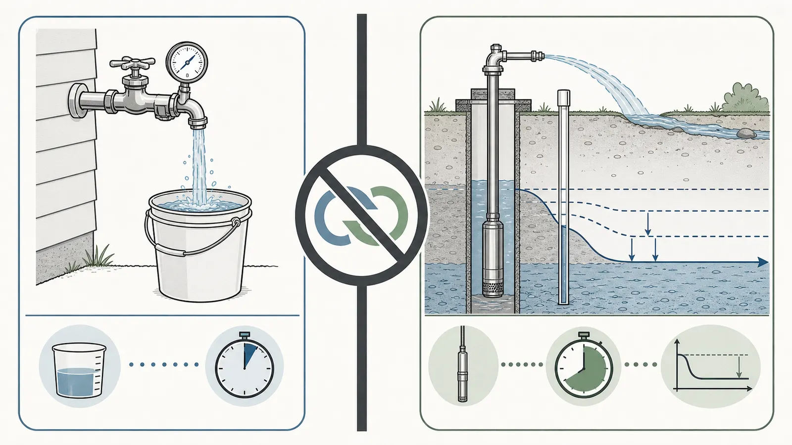
Measure a known volume at a safe spigot as close to the pressure tank as practical while the pump is running, and record gauge pressure at the same moment. Calculate GPM = gallons × 60 ÷ seconds, then repeat under load. This documents installed pump-system output at that location—not sustainable well yield. Compare it with actual peak demand and each treatment unit’s published service, minimum-pressure, and backwash requirements.How to Measure Well Pump Flow Rate: A Pressure-and-Flow Worksheet
The homeowner-safe screening test is simple: measure a known volume at a suitable spigot as close as practical to the pressure tank, time the capture while the pump is operating, and record the pressure-gauge reading at the same time. Calculate GPM = gallons × 60 ÷ seconds. Repeat the capture under the same load and keep the readings together with the test location and pressure.
That number is useful, but it has a narrow meaning. It is the installed pump-system output observed at that location, at that pressure, on that day. It is not automatically the pump’s catalog rating, the household’s peak demand, or the well’s sustainable yield. The distinction matters when you are deciding whether a filter, softener, ultraviolet unit, aeration system, or other whole-house treatment device can operate correctly.
This guide turns the measurement into a record a homeowner can reuse. It does not ask you to open a well, touch pump wiring, adjust a pressure switch, remove a fitting, or create a temporary high-pressure test rig.
1. Separate the four numbers before you measure #
“How many gallons per minute does my well produce?” can describe several different questions. Write the question beside the number so a precise-looking result does not get reused for a decision it cannot answer.
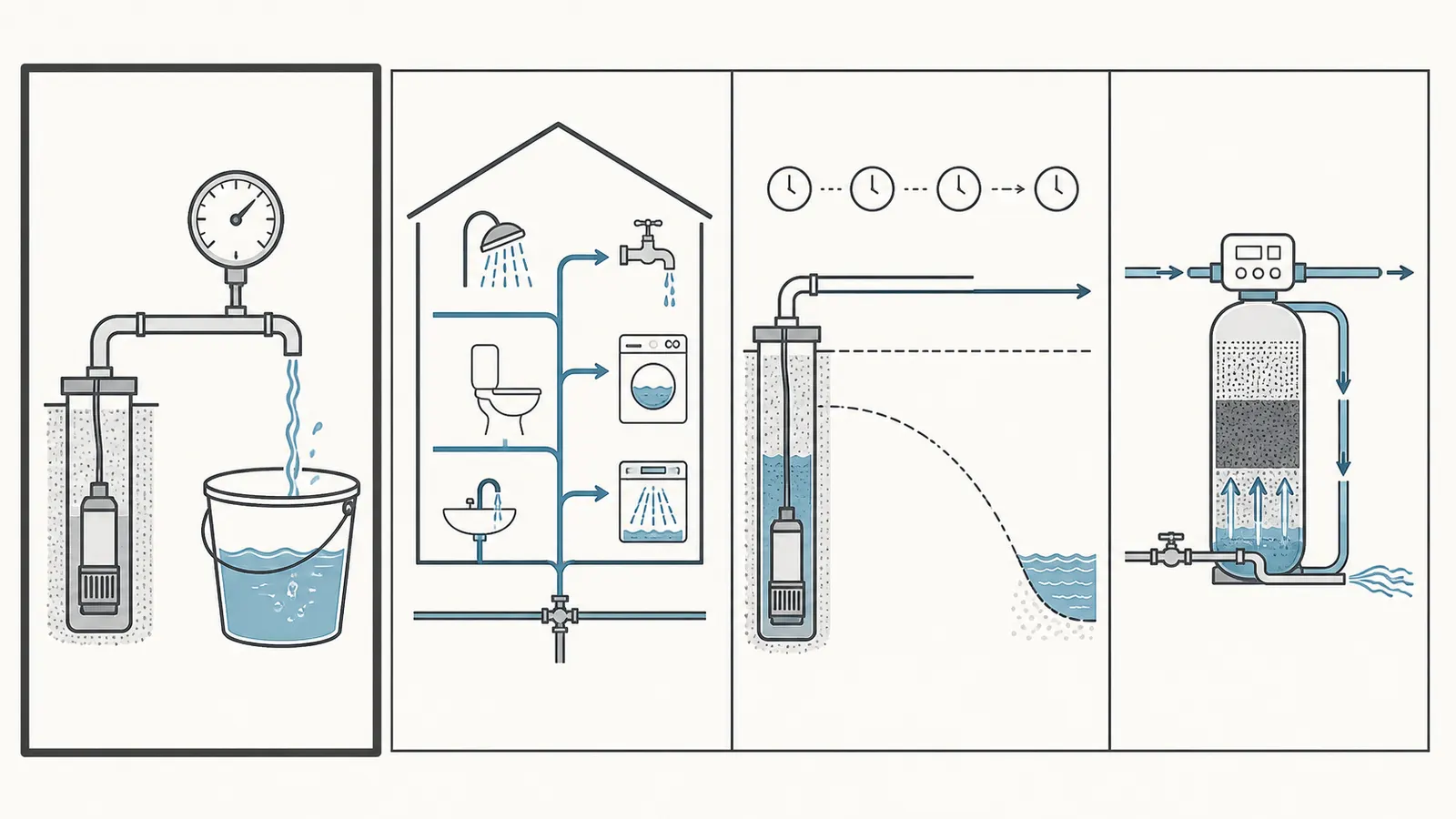
| Quantity | What it means | How this guide treats it | What it can support |
|---|---|---|---|
| Installed pump-system output | Water delivered at a named outlet while the system is operating under a named pressure and load | Homeowner measurement target | Screening a treatment proposal or documenting a symptom |
| Pump rating | A model’s published or recorded capacity under specified head, speed, and conditions | A reference only; not a substitute for current measurement | Identifying the equipment and giving a professional a starting point |
| Household peak demand | Water the home may need at the same time from fixtures and appliances | A separate estimate or measured demand | Deciding whether the house can serve simultaneous uses |
| Well yield or safe yield | The rate the source can deliver over a sustained pumping condition without unacceptable drawdown or loss of the pump intake’s water supply | Professional evaluation when this is the question | Assessing source adequacy, drought vulnerability, or low-yield options |
The Water Quality Association’s residential-treatment design guidance tells designers to study a private-well pump rating, pressure-switch setting, and main-pipe diameter, then evaluate output, pressure, daily volume, household demand, and the treatment manufacturer’s specifications. That is a design workflow, not permission to collapse all of those inputs into one bucket result.
The Penn State Extension explanation of low-yielding wells makes the same distinction from the source side: well yield is the maximum rate that can be pumped without lowering the water level below the pump intake. A well can refill enough over a day yet fail during a morning or evening peak. A measured outlet flow can therefore be perfectly repeatable and still leave the source-capacity question unanswered.
The decision this worksheet can answer
Use the test to answer:
“At this outlet, with the pump operating and the gauge reading about this pressure, what flow did the installed system deliver repeatedly?”
That answer is valuable for comparing a proposed treatment unit’s published requirements with an observed operating condition. It can also show that a low-flow complaint deserves follow-up. It cannot establish aquifer yield, water-level drawdown, pump horsepower, wiring condition, or the cause of a changing flow rate by itself.
2. Gather the record before opening a safe outlet #
The best test is not the one with the most equipment. It is the one whose conditions can be described and repeated. Before starting, fill in the top of the printable flow-and-pressure log or use a blank sheet with the same fields.
Record the system identity
Write down the date, time, address or system identifier, weather or drought concern if relevant, and the person observing. If you know them without opening anything, record:
- pump type or model and the model’s published flow information;
- pressure-tank model or nominal size, if shown on an exterior label;
- pressure-switch cut-in and cut-out settings from a readable label, service record, or existing documentation;
- pressure-gauge range and whether the gauge is at the tank or farther downstream;
- main pipe size if it is already documented;
- filter, softener, iron or sulfur treatment, ultraviolet unit, reverse-osmosis equipment, or other devices that were in service during the test;
- whether the test outlet is before or after those devices.
The WQA source identifies the pump rating and pressure-switch setting as private-well supply inputs, and the University of Florida IFAS pump-capacity publication explains why pressure and flow belong in the same record. If a label is unreadable, write “unknown.” Do not guess from a common household setting.
Assemble only homeowner-safe measuring equipment
Use:
- a container with a known volume, such as a bucket whose volume has been verified rather than assumed;
- a stopwatch or phone timer that can show seconds;
- a pen and the worksheet;
- a flashlight for observing a gauge or outlet, if needed;
- a hose or discharge path that will not flood the building, damage landscaping, or create a slip hazard.
For a rough estimate, the WQA procedure uses a five-gallon bucket or container. The UF/IFAS publication also describes a known-volume container and stopwatch as an approximate volumetric method, while noting that a flow meter is more direct. A larger container can reduce timing error, but it must be stable and its actual volume must be known. Never hold a heavy container in an awkward position beside energized or wet equipment.
Set the safety boundary first
This is an observation-and-measurement task, not pump service. Do not:
- open an electrical control box, pressure-switch cover, well cap, well seal, or wellhead;
- test live wiring, probe terminals, bypass a control, or reset an unknown electrical protection device;
- pull a pump, insert a water-level probe, lower a line into the well, enter a pit or confined space, or excavate a buried wellhead;
- loosen a gauge, relief valve, union, plug, hose connection, or other pressurized fitting;
- adjust the pressure switch, air charge, relief valve, pump setting, valve position, or treatment-control setting for this test;
- deliberately close a valve to create shutoff pressure or leave a pump running against a closed outlet;
- run water where it can reach electrical equipment, freeze, erode soil, contaminate a drain, or create a fall hazard.
The New Jersey Department of Environmental Protection private-well FAQ warns that opening a well can compromise sanitary integrity and that inserting a water-level device can damage pumping equipment. Its homeowner guidance also points owners with suspected well or pumping-equipment problems to licensed well drillers or pump installers. If the only possible test point requires service work, stop and request a qualified local evaluation.
3. Choose the test point and establish a baseline #
The test point determines what your result describes. Select the safest accessible outlet that is as close as practical to the pressure tank and upstream of treatment equipment, if the plumbing provides one. A tank-side spigot or discharge point is useful because it reduces the amount of house piping and treatment pressure loss between the pump system and the measurement. If that outlet is unavailable, use a suitable spigot and document its location.
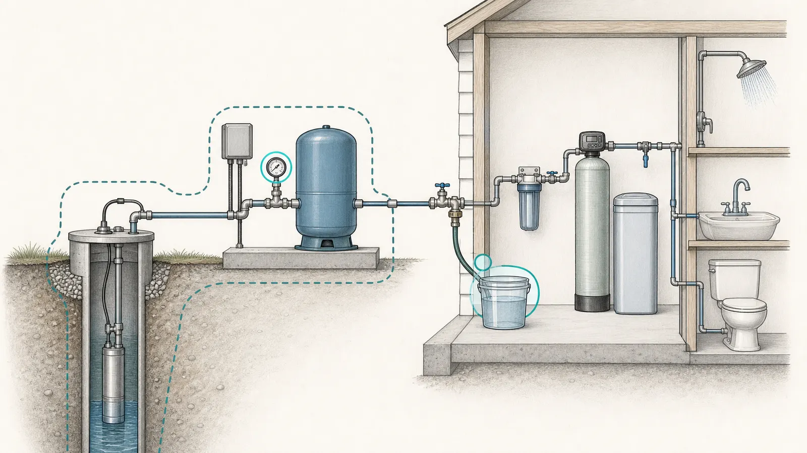
Do not remove a fixture or disconnect piping to create a test port. A normal hose bib or spigot that you can open and close without tools is the boundary assumed here. If you are unsure whether a valve is a service isolation valve, a relief valve, or a normal outlet, do not manipulate it.
Observe the starting condition
Before opening the outlet, note:
- Gauge pressure: Record the static reading visible before water is drawn. Call it “before flow,” not “pump pressure.”
- Pump state: Record whether the pump is off, running, or cycling, but do not open an enclosure to determine this. Audible operation or a visible gauge response may be enough; if it is unclear, write “unknown.”
- House demand: Turn off ordinary fixtures and appliances that would change the result. Do not interrupt a process that would be unsafe to stop; instead record it as a concurrent demand.
- Treatment state: Record whether cartridges, softeners, UV equipment, or other devices are in service, bypassed by an existing normal operating control, or unknown. Do not change a control merely to improve the number.
- Water appearance and sound: Note unusual sand, cloudiness, discoloration, air sputtering, a pump sound that differs from normal, or a long run time. These are observations, not diagnoses.
The NJDEP FAQ lists changing water appearance, altered pump sound, longer pump run time, and lower pressure as possible warning signs, while also noting that mechanical or electrical issues can look similar. A flow test should document those observations, not conceal them by repeatedly restarting the pump.
Define the load you are testing
A pressure-and-flow reading is meaningful only with a stated load. For the basic screen, the chosen outlet is the open load and the rest of the home is quiet. If the purpose is to assess a treatment unit, use the outlet and normal system arrangement that best represent the unit’s service path, then document every device between the gauge and the container.
If you need to know how the system behaves while a shower, hose bib, or appliance is also running, make that a separate labeled test. Do not mix a quiet-house result and a simultaneous-demand result into one average. A treatment designer or well professional may need both.
4. Measure GPM while recording pressure under load #
The following procedure is a conservative homeowner screen derived from the WQA field flow method and the UF/IFAS guidance to measure both discharge rate and pressure under operating conditions. It is deliberately narrower than a formal well-yield test.
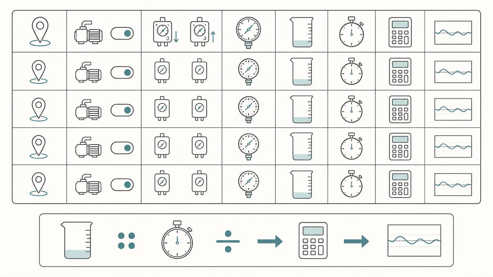
One test run
- Put the known-volume container where it will not tip or cause a hazard. Direct water to a safe discharge location.
- Confirm that the selected spigot is fully closed before the run and that the pump system is in its ordinary operating state.
- Open the spigot enough to produce a steady stream that can be captured. Do not force a valve, use a pressure-reducing restriction, or close an outlet against the pump.
- Watch the gauge from a dry, safe position. Note the pressure when the container begins filling. If the gauge is moving materially during the capture, record the beginning and ending values instead of pretending there was one stable pressure.
- Start the timer as the container begins collecting water. Stop it when the known volume is reached. Record the exact volume and elapsed seconds.
- Note whether the pump started, continued running, stopped, or cycled during the capture, using only safe observation. If the pump state cannot be determined, write that down.
- Close the spigot normally, confirm that water is not discharging where it should not, and let the system return to its normal condition. Do not open a control box or handle electrical equipment to do this.
The WQA worked example uses five gallons collected in 40 seconds: 5 ÷ 40 gallons per second, multiplied by 60, equals 7.5 GPM. Treat that as the source’s example, not a target for your home. Your worksheet should use your measured volume and time.
The calculation
Use this formula:
GPM = (known gallons ÷ elapsed seconds) × 60
Examples using hypothetical arithmetic only:
| Known volume | Elapsed time | Calculation | Result |
|---|---|---|---|
| 5 gal | 40 sec | (5 ÷ 40) × 60 | 7.5 GPM |
| 2 gal | 30 sec | (2 ÷ 30) × 60 | 4.0 GPM |
| 5 gal | 75 sec | (5 ÷ 75) × 60 | 4.0 GPM |
Use enough decimal places to avoid rounding a marginal result into a false pass. For a homeowner decision, one decimal place is usually easy to read, but preserve the original gallons, seconds, and pressure in the log so someone can recompute it.
Repeat the measurement without changing the question
Take at least three runs if the system remains stable and the discharge can be safely managed. Keep the test point, container, house-demand state, and treatment state the same. Let the system return to its ordinary condition between runs; do not deliberately drain or stress the well to manufacture a number.
For each run record:
- known gallons;
- elapsed seconds;
- calculated GPM;
- gauge pressure at the beginning and end, or a single reading only if it stayed visibly steady;
- pump state as observed;
- any sputtering, sand, cloudiness, unusual sound, cycling, or pressure collapse.
Use the median of three similar readings as the worksheet’s screening value only when the pressure and operating state are also similar. The median is a way to avoid letting one timing mistake dominate the record; it is not a certified test statistic. If the readings are widely separated or the pressure changes, report the range and the conditions instead of averaging away the problem.
The UF/IFAS discussion of pump capacity explains that manufacturer specifications do not include all site-specific effects and that measured capacity is valid only when operating conditions remain comparable. That is why the pressure column and notes column are not optional decoration.
5. Interpret the result with a diagnostic matrix #
Start with the evidence, not a diagnosis. Compare the runs, pressure, and symptoms in this matrix.
| Observation | What it supports | What it does not prove | Safest next step |
|---|---|---|---|
| Three similar GPM readings, similar pressure, no unusual symptoms | A repeatable installed-output screen at that test point | Sustainable well yield, pump health, or output at every fixture | Use the documented condition for a preliminary treatment check; retain the log |
| GPM is similar but pressure falls during capture | Flow was obtained across a changing pressure condition | That a treatment unit will receive its required pressure while flowing | Get the exact unit’s minimum pressure and pressure-drop data; consider qualified system review |
| GPM changes substantially between runs | The system is unstable or the test conditions changed | The average is a reliable design value | Stop repeating; document the range, pressure, pump behavior, and symptoms |
| Pressure drops and pump runs longer than usual | A possible well, water-level, mechanical, electrical, or flow-path issue | That the well is “dry” | Conserve water if appropriate and contact a qualified well/pump professional |
| Air, sputtering, sand, cloudiness, or discoloration appears | A condition worth recording and investigating | A specific failed part or unsafe-water conclusion | Stop if the change is significant; use a qualified evaluation and follow local water-testing advice |
| Good tank-side flow but poor flow after treatment | The pump-side screen may be adequate while downstream loss is limiting | That a new unit will work without pressure-loss data | Measure or obtain clean/loaded pressure-drop and flow specifications for the treatment train |
| Low tank-side flow at a stable-looking pressure | The installed system is not delivering the expected observed output | Whether the cause is pump wear, restriction, water level, controls, or source yield | Do not adjust controls; provide the log, equipment records, and symptom history to a professional |
When readings disagree
A single low reading can be a timing error, an incompletely filled container, a partially open outlet, or a gauge-reading mistake. A pattern is more informative. If the first run is high and later runs decline while the outlet and gauge remain open, note the time and change. That pattern may reflect the source, pump, control, a restriction, or the water level; it is not enough to name the failure.
If the pressure cycles during every capture, do not force the test into a single “operating pressure.” Record the cycle: for example, pressure at start, lowest visible pressure, pressure at finish, and whether the pump switched. A treatment unit may have a published minimum pressure and a service-flow range, so a GPM number without its pressure context can be misleading.
The NJDEP guidance emphasizes that low pressure and unusual run time can have more than one explanation. If there is a recent change from normal, preserve that history for the professional instead of trying to correct it through switch adjustments.
What the pressure gauge can and cannot tell you
The gauge tells you the pressure at its location at the moment you observe it. It does not tell you the pressure at a distant shower or at the inlet of a treatment unit unless those are the same point or pressure loss has been measured. Elevation, pipe size, fittings, filters, treatment media, and flow can change the pressure available downstream.
Likewise, a pressure-switch label tells you a control setting only if the label is legible and still corresponds to the operating system. It is not a homeowner instruction to open the switch or recalibrate it. Record the setting from existing documentation or a safely readable label; leave adjustment to qualified service.
6. Compare installed output with real demand and treatment requirements #
Once you have three comparable runs, make a second worksheet. List the demand you are trying to support and the exact requirements of every treatment device between the source and the house.
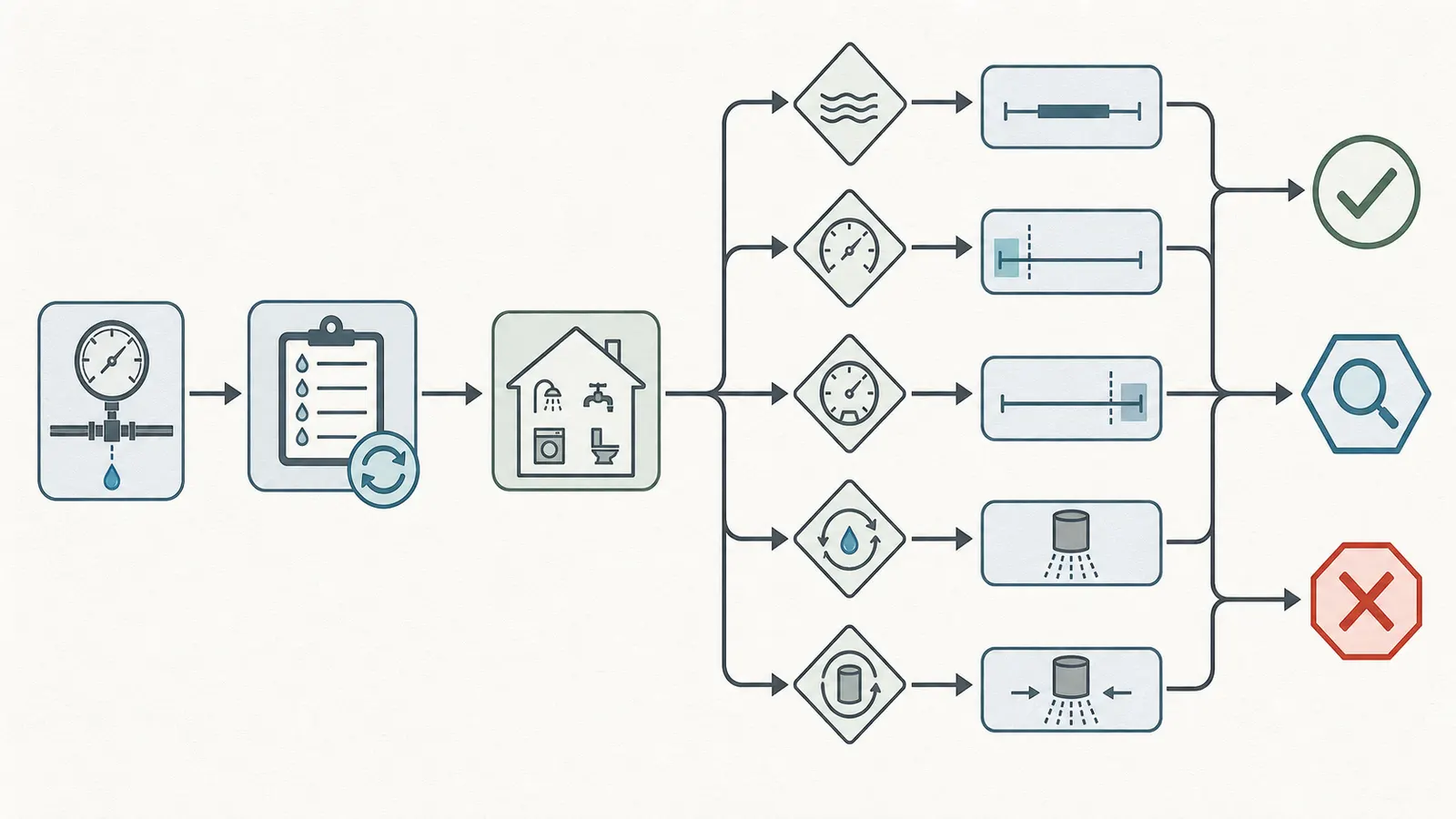
Household demand is not a pump test
Peak demand is the water the home may request at one time: simultaneous showers, toilet refill, a clothes washer, dishwasher, kitchen sink, hose bib, or other fixtures. Count the realistic combinations for your household, not an idealized occupancy. Record whether the proposed design assumes conservation fixtures, zoning, storage, or a limit on simultaneous use.
The WQA article explains that demand is often estimated from fixtures and local plumbing-code procedures, but it also notes that real peak demand can differ from code-based estimates and that local codes should be referenced. Do not copy a fixture-unit table from another state into a permit or design decision. For this worksheet, label the demand source as one of:
- observed simultaneous flow at a named fixture combination;
- a manufacturer, designer, or local-code calculation;
- a household estimate with stated assumptions;
- unknown.
If demand is unknown, the result is “not demonstrated,” not “pass.”
Treatment flow requirements are model-specific
For each proposed or existing unit, collect the exact model number and manufacturer literature. Record:
| Requirement to copy from the exact source | Why it matters |
|---|---|
| Service-flow range or maximum service flow | Too much flow can reduce contact time or cause contaminant breakthrough in some treatment designs; the unit’s own documentation controls |
| Minimum operating pressure | A flow number is not useful if the unit cannot operate at the pressure available while water is flowing |
| Maximum operating pressure | The system must remain within the unit’s rated or published pressure limits |
| Backwash, rinse, or regeneration flow | The source must support the required flow at the stated pressure and duration, not merely a daytime faucet flow |
| Pressure drop at a stated flow | Existing filters and treatment media can consume pressure before the next device or fixture |
| Drain, waste, and electrical requirements | Backwash or regeneration may need a suitable drain path and power; verify the exact installation requirements |
| Water-quality and pretreatment assumptions | Flow compatibility does not prove the treatment technology is appropriate for the contaminant or concentration |
The WQA design article says treatment equipment must be matched to supply flow rate, daily volume, pressure, and manufacturer specifications. It also warns that excessive flow can contribute to contaminant breakthrough in undersized equipment and that inadequate flow can interfere with regeneration. Those are reasons to copy the exact published requirement into the log rather than use a universal “well pump GPM” rule.
A conservative compatibility screen
For an initial screen, compare like with like:
Observed installed output at the relevant pressure
        versus
the exact unit's required service or backwash flow at its stated pressure
Then account for the rest of the train. If the tank-side test is 8.0 GPM at a stated gauge pressure but a treatment unit’s requirement is 8.0 GPM at a different pressure, the comparison is incomplete. If a filter, softener, or other device is already between the gauge and the proposed unit, its pressure drop must be included. If the pump produces enough flow only at a pressure below the unit’s minimum, that is not demonstrated compatibility.
Use these labels in the worksheet:
- Supportable at this test condition: repeat readings meet or exceed the exact published flow requirement, pressure is within the unit’s stated range, and downstream pressure loss and drain requirements are accounted for.
- Not demonstrated: the model requirement, operating pressure, pressure drop, backwash condition, or downstream path is missing.
- Do not proceed on this result: flow is unstable, pressure collapses, the pump runs abnormally, the source shows low-water signs, or the unit’s requirement exceeds the observed condition.
These labels describe evidence quality, not a product approval. A treatment professional still needs the water-quality test and the full equipment specifications to select appropriate technology.
7. Know when a formal well-yield or pump evaluation is required #
The homeowner screen should end when the unanswered question moves below the outlet. Request qualified local help when you need to know the water level, drawdown, source recovery, pump setting, pump condition, electrical behavior, or sustainable yield.
Source-side questions
Stop treating the bucket number as sufficient when:
- the result falls with continued pumping or changes materially between otherwise comparable runs;
- the pump runs longer than usual, pressure is lower than normal, or water appearance changes during drought or seasonal low-water conditions;
- the home has a history of running out of water, air in the lines, sand, or a pump that loses delivery;
- you need a sustained yield for a new home, irrigation, pool filling, commercial use, or a major treatment/backwash design;
- a well log, purchase inspection, or old pump test is being used as proof of current capacity;
- the test requires opening the well, inserting a probe, accessing a buried wellhead, removing equipment, or changing controls.
The Connecticut Department of Public Health safe-yield guidance describes yield as water that may be pumped continuously and discusses extended pumping, stabilization, and local requirements. Its suggested approach for checking an older home’s present yield uses a discharge-line water meter and a stabilized discharge with a licensed plumber or well driller. Its test periods and code references are Connecticut-specific; they are not a national homeowner rule. The transferable lesson is that sustained yield needs a different observation window and professional controls than a bucket capture.
Pump- and system-side questions
Ask a qualified well/pump professional to evaluate the system if you see:
- a gauge that does not respond normally or a pressure reading that is implausible for the documented system;
- rapid cycling, failure to stop, failure to build pressure, unusual motor or pump sounds, or an electrical trip;
- large differences between tank-side and downstream readings that cannot be explained by a known filter or treatment device;
- flow that is erratic, full of air, visibly sandy, or associated with a new taste, odor, or discoloration;
- a need to change a pressure-switch setting, inspect a control, work on a pump, handle a pressurized fitting, or access the well.
The professional should be chosen according to local licensing and scope. NJDEP specifically distinguishes licensed well drillers and pump installers for well and pumping-equipment work; another state may use different licenses or titles. Use your state or local health department and well-permitting authority for the applicable route.
What to bring to the professional
Send the log before the visit if possible. Include:
- the test location and whether it was before or after treatment;
- pressure before flow and during each capture;
- volume, seconds, calculated GPM, and all repeat values—not only the best one;
- pump state as observed and any long-run, cycling, or sound changes;
- recent water appearance, taste, odor, sediment, or air observations;
- pump, tank, pressure switch, gauge, treatment, and water-test records;
- the actual decision you need made: household peak demand, treatment service flow, backwash flow, drought resilience, or source yield.
That packet lets the professional decide whether to perform a flow-meter test, pressure and electrical diagnostics, water-level/drawdown work, well rehabilitation review, storage assessment, or treatment redesign. You do not have to decide which hidden component failed before requesting help.
8. Turn the result into a reusable decision record #
The final record should preserve uncertainty as carefully as it preserves the GPM calculation. On the printable log, fill in the summary only after the repeat rows are complete.
Summary fields
Record:
- test date and time;
- outlet and gauge location;
- pressure-switch settings, if known from safe documentation;
- treatment devices in service and any known bypass state;
- house-demand condition;
- each run’s volume, seconds, pressure, pump state, and GPM;
- the range and, only if appropriate, the median of comparable readings;
- exact treatment model requirements and their source documents;
- the decision label: supportable at this test condition, not demonstrated, or professional review required;
- what this test did not establish: sustainable yield, drawdown, electrical condition, pump condition, or downstream pressure unless separately measured.
Maintenance and repeat timing
Keep the log with the well and treatment records. Repeat a comparable screen when there is a meaningful change: a new pump or tank, new treatment equipment, a new pressure complaint, a change in pump run time, seasonal or drought concern, or a major household demand change. Do not compare numbers from different outlets or pressure conditions without labeling the difference.
The UF/IFAS source notes that changes in water level and other site conditions can change pump output. The Penn State source notes that well yield and low-yield behavior are tied to peak demand and limited storage. A seasonal log can therefore show a trend worth professional attention, but it still does not become a formal safe-yield certification.
The one-sentence handoff
When someone asks, “What is your well pump flow rate?” answer with the full condition:
“At the [named outlet], with [treatment state] and about [pressure] psi during capture, the installed system delivered [range] GPM across [number] comparable runs on [date]. This was not a sustainable well-yield or drawdown test.”
That sentence is less convenient than a single number and much more useful. It tells a treatment designer what was actually observed, gives a pump professional a starting point, and keeps an unresolved source-capacity question visible.
Well-Pump Flow and Pressure Log
A printable, reusable log for test location, pressure, known volume, elapsed time, repeat GPM, household demand, treatment requirements, and professional follow-up.
Download the worksheet (PDF)Cite this guide
Brictale. “How to Measure Well Pump Flow Rate: A Pressure-and-Flow Worksheet.” Published 2026-08-24; updated 2026-08-24.
https://brictale.com/water/pumps/measure-well-pump-flow-rate · Read the Markdown version
Sources and scope
Evidence behind this page
- For a private-well water system, a supply review should record the pump rating, pressure-switch setting, and main water-system pipe diameter before evaluating output capability.
Residential Water Treatment Design
WQA residential water-treatment design article, pages 5-6; source-specific design guidance, not a national code or universal pump test standard.
Accessed · Link to this claim - A known-volume container and stopwatch can estimate well-pump flow by opening a spigot at or near the well-tank piping, observing pump operation, timing the fill, and converting gallons per second to gallons per minute.
Residential Water Treatment Design
WQA on-site well flow-test procedure and worked example, page 6; supports a field estimate at that test location and condition.
Accessed · Link to this claim - Treatment equipment should be matched to water-supply flow rate, pressure, daily volume, and the equipment manufacturer's operating specifications; excessive service demand or inadequate regeneration flow can cause performance or equipment problems.
Residential Water Treatment Design
WQA treatment-design guidance, pages 4, 6, and 9-10; not a performance guarantee for any unlisted treatment model.
Accessed · Link to this claim - Pump capacity has both discharge-rate and discharge-pressure components, and both should be measured under normal operating conditions; a known-volume container and stopwatch provide an approximate flow estimate while a gauge measures pressure.
Measuring Pump Capacity for Irrigation System Design
University of Florida IFAS publication; irrigation design context, applied here only for the measurement principle that flow and pressure are paired operating-condition observations.
Accessed · Link to this claim - Pump capacity can change with well water level, aquifer or source conditions, pump wear, pipe size, intake or check-valve condition, and other site factors; a measurement is valid only when operating conditions are comparable.
Measuring Pump Capacity for Irrigation System Design
University of Florida IFAS publication, factors affecting head-discharge curves; the source discusses irrigation systems and does not establish a residential well-yield test duration.
Accessed · Link to this claim - Well yield is the maximum rate a well can be pumped without lowering the water level below the pump intake, and a low-yielding well may fail to meet peak household demand even if its daily production could be large enough when spread across a full day.
Penn State Extension publication updated September 8, 2025; household and farm low-yield well planning context.
Accessed · Link to this claim - A pressure tank primarily maintains pressure and has limited usable storage; Penn State gives an approximate example of about 20 percent of nominal tank capacity as usable water in common cases, while noting that larger tanks alone may not solve a low-yield problem.
Penn State Extension pressure-tank storage discussion; examples are approximate and not a substitute for the exact tank chart or measured drawdown.
Accessed · Link to this claim - A short household flow capture is not the same as a formal safe-yield or well-yield test; Connecticut guidance describes yield as continuously deliverable water and discusses extended pumping, stabilization, and drawdown-related evaluation.
Private Well Guidance for Determining Well Safe Yield
Connecticut Department of Public Health Publication No. 28, June 2009; Connecticut-specific guidance and code references, not a national duration requirement.
Accessed · Link to this claim - For an older home, Connecticut guidance suggests that a licensed plumber or well driller can install a low-capacity water meter on the discharge line and run the well until discharge stabilizes when a present-yield check is needed without removing the pump.
Private Well Guidance for Determining Well Safe Yield
Connecticut Department of Public Health guidance, page 2; explicitly assigns the discharge-line meter and stabilized test to licensed professionals.
Accessed · Link to this claim - NJDEP lists longer-than-usual pump run time and lower water pressure among possible signs of a drought or private-well problem, while noting that electrical or mechanical pump issues can produce similar symptoms.
New Jersey Department of Environmental Protection homeowner FAQ; symptom guidance, not a diagnosis or nationwide regulatory rule.
Accessed · Link to this claim - NJDEP directs owners with suspected well or pumping-equipment problems to licensed well drillers or pump installers and warns that opening a well or inserting water-level devices can compromise sanitary integrity or damage equipment.
New Jersey Department of Environmental Protection FAQ; licensing and well-opening statements are New Jersey-specific, while the conservative safety boundary is used here as homeowner guidance.
Accessed · Link to this claim