Whole-House Carbon Filter EBCT Calculator: A Quote-Check Worksheet
Calculate whole-house carbon EBCT from real media volume and flow, reverse-solve the quote, and expose the contaminant and maintenance evidence still missing.
The short answer
EBCT is empty-bed volume divided by flow. Convert the quoted carbon bed to gallons, divide by the measured or design peak flow, and compare the result only with a contaminant-specific manufacturer, pilot, or comparable-system basis. Use the worksheet to compare single-vessel and lead/lag layouts, but do not treat EBCT as proof that a carbon tank removes a named contaminant.Whole-House Carbon Filter EBCT Calculator: A Quote-Check Worksheet
EBCT is a useful way to compare the hydraulic part of a whole-house granular activated carbon (GAC) quote, but it is not a universal “carbon removes this contaminant” calculator. EPA defines empty-bed contact time as empty-bed volume divided by volumetric flow rate. EPA also says the required value changes with the contaminant, removal target, carbon type, competing chemicals, and other influent-water conditions, and is best established through pilot work or experience with similar water. (EPA’s GAC design documentation)
Use this page to do four things:
- turn a quote’s actual media volume and design flow into EBCT;
- reverse-solve the maximum flow or minimum media volume for a documented EBCT basis;
- compare a single vessel with a two-vessel lead/lag arrangement; and
- identify the evidence still needed before treating a carbon system as a credible answer to a private-well contaminant result.
The result is a quote comparison, not a treatment approval. If a proposal names PFAS, a volatile organic compound, pesticide, radon, fuel-related chemical, taste-and-odor problem, or any other contaminant, keep the water safe according to your laboratory, state or local health authority, and qualified treatment professional while the design is being evaluated. Do not infer removal from tank size, black media, a generic “carbon” label, or EBCT alone.
1. Decide whether the number you have is usable #
Before doing arithmetic, identify what the quote is actually describing. “One cubic-foot carbon tank” can mean a vessel marketed by nominal size, a vessel filled with less than one cubic foot of media, or a system whose performance was tested at a particular flow and contaminant concentration. EBCT uses the volume of the empty bed occupied by the carbon media, not the outside dimensions of the tank and not automatically the number printed in a product name.
EPA’s GAC model treats contaminant, flow, carbon life, removal requirement, number of contactors, bed depth, and contactor dimensions as design inputs. (EPA’s GAC model input documentation) Treat each blank in the following table as a decision gate.
| Input to collect | What counts as usable evidence | If it is missing |
|---|---|---|
| Target contaminant | Dated laboratory report naming the compound or parameter, concentration, units, sample point, and method or lab report details | Do not compare a generic carbon claim |
| Treatment objective | A stated treated-water target, applicable benchmark, or manufacturer performance claim tied to the exact water conditions | EBCT is screening only |
| Carbon identity | Media manufacturer, grade or product name, raw material if specified, and current technical data | Do not treat “premium carbon” as a design input |
| Empty-bed volume | Media volume in cubic feet or gallons, with fill level and whether the number is per vessel or total | Ask the seller to separate vessel, media, and total-bed volume |
| Vessel arrangement | One vessel, lead/lag series, parallel branches, or another flow path with a diagram | Do not add volumes until the flow path is known |
| Design flow | Flow used for the carbon performance claim, including whether it is peak, average, continuous, or intermittent | The EBCT result is not comparable |
| Home flow evidence | A measured peak-use observation, a pump or system design flow, or a documented flow limit | Do not substitute horsepower or pipe size |
| Pretreatment | Sediment, iron, manganese, oxidant, softening, or other upstream treatment and its maintenance requirements | Ask what fouling or competing chemistry the design assumes |
| Breakthrough basis | Capacity, replacement trigger, treated-water limit, bed volumes, or a test/monitoring plan | Do not accept a calendar promise without its basis |
| Pressure and head loss | Inlet/outlet pressure or differential-pressure limits at the stated flow, plus required flow limiter | A tank can pass EBCT and still starve the home of pressure |
| Verification | Exact certification, lab data, pilot results, or comparable system evidence for the named contaminant | Route to a qualified professional or certified lab |
One state example illustrates why these fields matter without becoming a national rule. New York’s appendix for activated-carbon systems serving individual water supplies addresses flow control, sample taps, pressure gauges before and after the carbon, pretreatment where appropriate, disinfection, and pressure limits in addition to its EBCT language. (New York Appendix 75-B.2) That is a New York requirement and technical example, not a rule that automatically governs a home elsewhere.
Stop if the water-quality question is unresolved
EPA recommends that private-well owners test annually for total coliform bacteria, nitrates, total dissolved solids, and pH, test for additional contaminants when local conditions or symptoms suggest them, and use a laboratory certified for drinking-water testing. (EPA’s private-well testing guidance) A carbon quote cannot tell you what is in the well. A color, odor, or taste can prompt investigation, but it cannot identify a contaminant or establish a safe concentration.
Connecticut’s private-well guidance describes GAC as commonly used for chemical contaminants and taste and odor, while cautioning that it is not considered effective for microorganisms, some metals, or nitrates. It also says effectiveness depends on the carbon type, contaminant type and concentration, and filter size. (Connecticut Department of Public Health’s GAC guidance) Treat that list as a screening warning, not as permission to use GAC for a contaminant without claim-specific evidence.
2. Enter the EBCT inputs and convert the units #
The base equation is:
EBCT (minutes) = empty-bed volume (gallons) ÷ flow (gallons per minute)
If the quote gives cubic feet of carbon media, convert first:
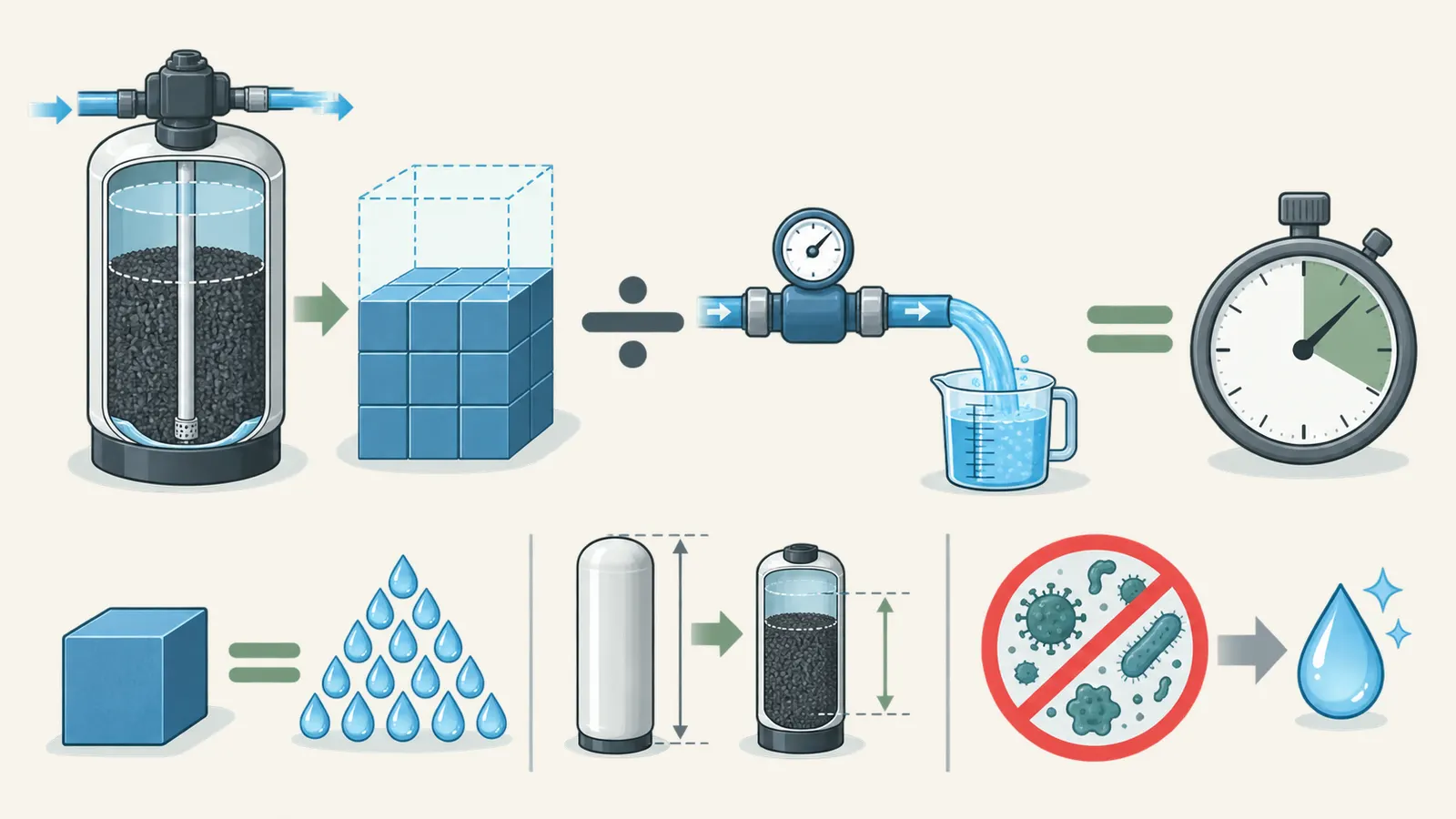
empty-bed volume (gallons) = media volume (cubic feet) × 7.48052
Combined in one line:
EBCT (minutes) = media volume (cubic feet) × 7.48052 ÷ flow (gpm)
The reverse calculations are just as important when checking a proposal:
required media volume (cubic feet) = flow (gpm) × target EBCT (minutes) ÷ 7.48052

maximum flow (gpm) = media volume (cubic feet) × 7.48052 ÷ target EBCT (minutes)
Use the flow that belongs to the quoted design basis. A measured faucet flow can help expose a mismatch, but it is not automatically the pump’s available flow at all pressures and fixtures. A peak-flow value from a treatment quote may be a continuous flow, a design flow, or a short-duration maximum; ask which one. If a flow limiter is part of the design, record its setting and what happens when demand exceeds it.
A worked comparison with no contaminant promise
Suppose a quote documents one cubic foot of GAC media and a 5 gpm design flow. The hydraulic screening result is:
1.0 cubic foot × 7.48052 gallons per cubic foot ÷ 5 gpm
= 1.496 minutes EBCT
Now suppose a second quote uses two vessels in series, each with one cubic foot of media, at the same 5 gpm:
vessel 1: 1.0 × 7.48052 ÷ 5 = 1.496 minutes
vessel 2: 1.0 × 7.48052 ÷ 5 = 1.496 minutes
total series EBCT: 1.496 + 1.496 = 2.992 minutes
The second design has about twice the total empty-bed volume at that flow. That does not mean it removes twice as much contaminant, lasts twice as long, or meets a health target. It means the hydraulic contact-time calculation is different and the arrangement creates a place to monitor the water between vessels.
If the same two-vessel system is asked to support 10 gpm, each vessel’s EBCT becomes 0.748 minutes and the total becomes 1.496 minutes. The system’s result changed because flow changed. The homeowner’s peak demand, not the marketing flow printed on a low-demand product page, is the comparison that matters.
Record the result without false precision
Use enough decimals to show the arithmetic, then round the displayed EBCT sensibly. The input quality usually does not justify reporting a result such as 1.496104 minutes as if the home’s flow were known to six decimal places. Keep the unrounded calculation in the worksheet, but report “about 1.50 minutes” and document the source and date of each input.
| Field | Entry |
|---|---|
| Media volume per vessel | ______ cubic feet |
| Number of vessels contributing in the stated flow path | ______ |
| Total active empty-bed volume | ______ cubic feet or ______ gallons |
| Flow used for the calculation | ______ gpm |
| Per-vessel EBCT, if series | ______ minutes |
| Total series EBCT | ______ minutes |
| Flow source and date | ______________________________ |
| Quote or manual page | ______________________________ |
| Result status | comparable / flow-limited / evidence missing |
Do not count a bypass branch, an empty vessel, a vessel isolated for maintenance, or a parallel vessel that does not receive the same flow. If the quote does not include a piping diagram, ask the installer to draw the normal operating path and the maintenance path.
3. Reverse-solve the quote’s flow limit or media requirement #
A quote may publish “20 minutes EBCT” without saying whether that value is at average daily flow, peak flow, or a controlled maximum. EPA’s GAC documentation distinguishes average and design flow and makes flow a core design input. (EPA’s GAC design documentation) Ask the seller to identify the flow basis before comparing the number with your house.
Reverse-solve the maximum flow
If the manufacturer or qualified designer provides a contaminant-specific target EBCT, calculate the flow ceiling implied by the quoted media:
maximum flow = media volume × 7.48052 ÷ target EBCT
Example: a two-vessel series train has 2.0 cubic feet total media and a documented target of 3 minutes total:
2.0 × 7.48052 ÷ 3 = 4.987 gpm maximum flow
That is a hydraulic result under the stated assumptions. It does not prove the carbon has the right adsorption properties or capacity. If household demand can reach 8 gpm, the proposal either needs more media, a lower controlled flow, a different treatment train, a documented storage strategy, or a professional redesign. A flow limiter can protect EBCT only if the whole system still delivers acceptable pressure and the owner understands what happens when the limit is exceeded.
Reverse-solve required media volume
If a qualified design basis specifies 10 minutes at 6 gpm:
6 × 10 ÷ 7.48052 = 8.02 cubic feet of media
The result is not a recommendation to install 8.02 cubic feet. It is the amount of empty-bed media implied by that particular target and flow before vessel geometry, bed depth, backwash, pressure drop, carbon grade, and contaminant-specific performance are checked. A quote offering 1 cubic foot for that same stated basis has an arithmetic mismatch; a quote offering 8.02 cubic feet still needs evidence that the basis is appropriate.
Do not borrow a target from another contaminant
EPA reports example EBCT values for several treatment designs, but the same document says the required EBCT varies by contaminant, removal percentage, GAC type, and influent characteristics. It describes typical values and model assumptions in their specific contexts, including pilot-derived or peer-reviewed design assumptions. (EPA’s discussion of contaminant-removal requirements) A value that appears in a PFAS design, a radon design, or a public-water rule is not a default for your private well.
New York’s 2021 GAC recommendations make the same decision point explicit: if small-scale or pilot testing is not completed, the design parameter values should be justified from systems with similar water quality, contaminant concentrations, and treatment requirements. (New York’s GAC design-review recommendations) For a homeowner, that means asking the quote writer to provide the basis in writing instead of asking a generic calculator to invent it.
4. Compare single-vessel and lead/lag layouts #
The arithmetic and the risk-management layout are separate decisions. A single vessel may have the same total media volume as two smaller vessels, but it does not provide a sampling point between beds or a second bed ready to polish water after the lead bed begins to exhaust. Two vessels in series can also impose different pressure-drop, backwash, footprint, and maintenance requirements.
EPA describes a series arrangement in which the first vessel acts as a roughing vessel and later vessels act as polishing vessels; when the roughing carbon is spent, the vessels can be repositioned so new carbon becomes the polishing bed. (EPA’s GAC series-operation discussion) Connecticut DPH likewise describes pre-, mid-, and post-filtration sampling for two filters in series and a changeout sequence based on the midstream sample. (Connecticut’s GAC testing guidance) Those sources support asking for a monitoring plan; they do not make every lead/lag installation safe or effective.
| Comparison point | Single vessel | Lead/lag series |
|---|---|---|
| EBCT math | Total active media ÷ design flow | Sum of each vessel’s EBCT at its actual series flow |
| Breakthrough visibility | Usually only before/after evidence unless internal ports exist | Pre-, between-, and post-vessel sampling can show the lead bed approaching exhaustion |
| Maintenance continuity | May require bypass or outage during media service | Can allow planned changeout and vessel-role rotation if valves and procedures support it |
| Failure consequence | One exhausted bed can send untreated water downstream | Lag bed may provide additional protection, but only while it has capacity and the flow path is correct |
| Pressure and footprint | Fewer vessels, but not automatically lower pressure loss | More fittings and media; head loss must be checked per vessel and at peak flow |
| Quote evidence needed | Exact media volume, capacity, flow, replacement trigger | All of the single-vessel fields plus vessel order, switch-over procedure, sample locations, and role labels |
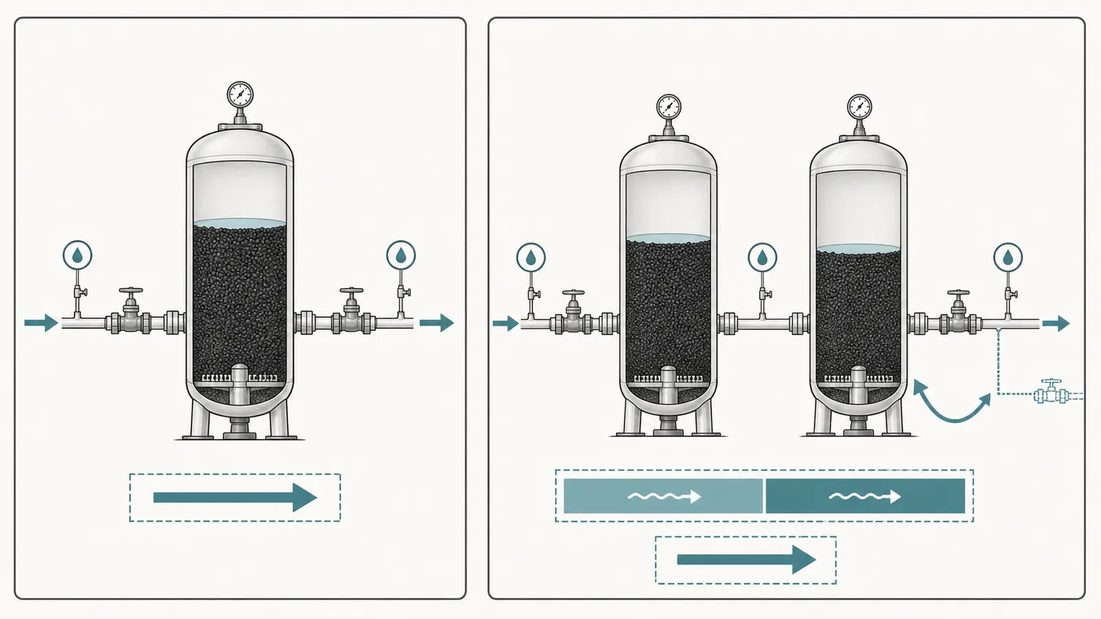
New York’s recommendations say contactors may be series, parallel, or another approved configuration in their reviewed context, and that each contactor should be able to provide the required treatment when operated alone during certain maintenance states. They also call for anticipated head loss, pressure gauges, flow meters, isolation valves, and sample taps in the design and operating plan. (New York’s GAC operating considerations) Treat this as a high-quality checklist for a quote, not as a universal homeowner code requirement.
Check parallel layouts differently
In a parallel design, flow divides between branches. The total-volume-over-total-flow shortcut is valid only when the stated flow distribution and active bed volumes are known and the branches are hydraulically balanced. If one branch receives more flow, its EBCT is lower than the system average. Ask for the per-branch flow, media volume, balancing method, and the condition used to rate the contaminant claim.
If the seller says “two tanks in parallel double capacity,” ask whether “capacity” means flow capacity, media adsorption capacity, or redundancy. Those are different. Parallel vessels can increase available flow while leaving each vessel at a lower EBCT than a series train with the same total media. The quote should state which performance outcome the arrangement is intended to achieve.
5. Keep EBCT separate from contaminant removal #
Carbon is an adsorbent, not a universal sieve. EPA says GAC service life varies with carbon properties and site conditions, and it describes breakthrough as the point when treated-water concentration reaches the unacceptable level selected for the design. (EPA’s carbon-life documentation) EBCT tells you how much empty bed and flow were used. It does not tell you the contaminant’s adsorption affinity, the capacity before breakthrough, or the treated concentration at the outlet.
The design evidence should answer these questions:
- What exact contaminant or compounds are being treated?
- What are the influent concentrations, units, sample date, and sample location?
- What treated-water concentration or reduction target is required?
- What carbon grade and media properties were used to support the claim?
- What competing organics, pH, dissolved organic carbon, iron, manganese, turbidity, chlorine, or other chemistry was assumed?
- What flow, temperature, pressure, bed depth, and EBCT were used in the test or comparable installation?
- What breakthrough concentration or replacement trigger ends the claim?
- What sampling and laboratory method will verify startup and ongoing performance?
NSF explains that residential treatment certification is claim-specific: certification to an NSF/ANSI standard or protocol does not mean a filter reduces every possible contaminant, so the exact contaminant of concern must be matched to the applicable listing. (NSF’s standards guidance) A logo, a standard number without a named reduction claim, or certification of a component rather than the complete system is not enough to establish the result you need.
Recognize the unsafe inference branches
| What the quote says | What you may conclude | What you may not conclude |
|---|---|---|
| “1 cubic foot of carbon” | You can calculate a provisional EBCT after confirming actual media volume and flow | The tank meets a contaminant target |
| “20-minute EBCT” | The seller has stated a hydraulic basis, if flow and volume are documented | Twenty minutes is right for every contaminant |
| “Removes chemicals” | The quote is making a broad marketing statement | It removes your named compound to a safe level |
| “NSF certified” | A certification claim may be verifiable in a directory | All contaminants are reduced or the whole installed train is certified |
| “Two tanks in series” | There may be a lead/lag monitoring and maintenance path | The lag vessel will prevent breakthrough without capacity and maintenance evidence |
| “Replace annually” | The seller has offered a maintenance interval to investigate | One year is safe regardless of use, concentration, carbon, or breakthrough |
| “Peak flow 5 gpm” | The quote uses a stated flow basis | Your home never exceeds 5 gpm or the pump can sustain it |
If the treated water may contain a harmful contaminant, do not keep drinking it while waiting for a filter to be installed or verified. Connecticut DPH describes bottled water or another alternative source as a possible temporary option in some contamination situations, and EPA directs private-well owners to certified laboratories and local health contacts for testing questions. (Connecticut’s private-well GAC guidance, EPA’s private-well guidance) The correct exposure boundary depends on the contaminant and local health advice.
6. Measure household flow without servicing the system #
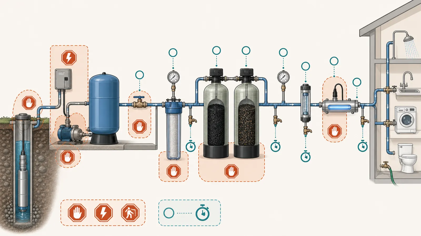
The safest homeowner contribution is a repeatable observation from a normal fixture, not an adjustment inside the well system. Do not open an energized control enclosure, test live wiring, open the well, pull a pump, enter a well pit or other confined space, loosen pressurized fittings, remove a relief valve, change pressure-switch settings, open a filter vessel, handle spent carbon, or manipulate a pressurized component. Do not disconnect a sample line or alter a bypass to create a test condition. A qualified professional should perform pressure, flow, electrical, pump, vessel, media, valve, and treatment-train service.
A safe timed-flow procedure
Use only a normal household cold-water fixture that can be operated without removing plumbing or exposing electrical or pressurized parts. Stop if the fixture, floor, drain, or vessel area is wet, damaged, unstable, or otherwise unsafe.
- Choose one fixture and write down its location, date, time, and whether the carbon system is in its normal operating position. Do not change the valves.
- Use a container with a known volume. A marked 1-gallon container is easier to compare than an unmarked bucket. Keep the container stable and keep water away from electrical equipment.
- Open the fixture to the same practical position each time. Start a timer and collect for a measured interval, such as 15 or 30 seconds. Stop if the fixture sputters, the drain backs up, or the system behaves abnormally.
- Convert the result to gpm:
flow (gpm) = collected gallons × 60 ÷ seconds
- Repeat at least twice under the same conditions. Record the range, not just the largest number. If the pump cycles or pressure changes during the test, record that event.
- Repeat at the fixture most likely to represent peak whole-house use only if it can be done safely. A single faucet is not the same as simultaneous showers, laundry, toilets, irrigation, or other demand.
- Give the observations to the installer or pump professional and ask whether the quote’s design flow is a measured system flow, a controlled maximum, a pump-curve point, or an assumption.
This test can identify an obvious mismatch, such as a quote rated at 5 gpm when a safe fixture observation repeatedly reaches a higher flow before the system’s normal pressure cycle. It cannot prove pump capacity, well yield, carbon performance, or contaminant removal. A professional may need pump-curve, pressure, storage, or system-level measurements that are outside homeowner service.
Record pressure drop, don’t create it
If the installed train already has accessible gauges before and after the carbon, photograph or transcribe the readings from a safe dry location while the system is operating normally. Do not install gauges, remove plugs, or open a vessel for this page. A difference between inlet and outlet pressure is evidence to discuss with the installer; it is not a universal pass/fail value. New York’s GAC recommendations specifically call for anticipated head loss and gauges before and after contactors in their reviewed designs. (New York’s pressure and flow considerations)
7. Turn the calculation into a quote decision #
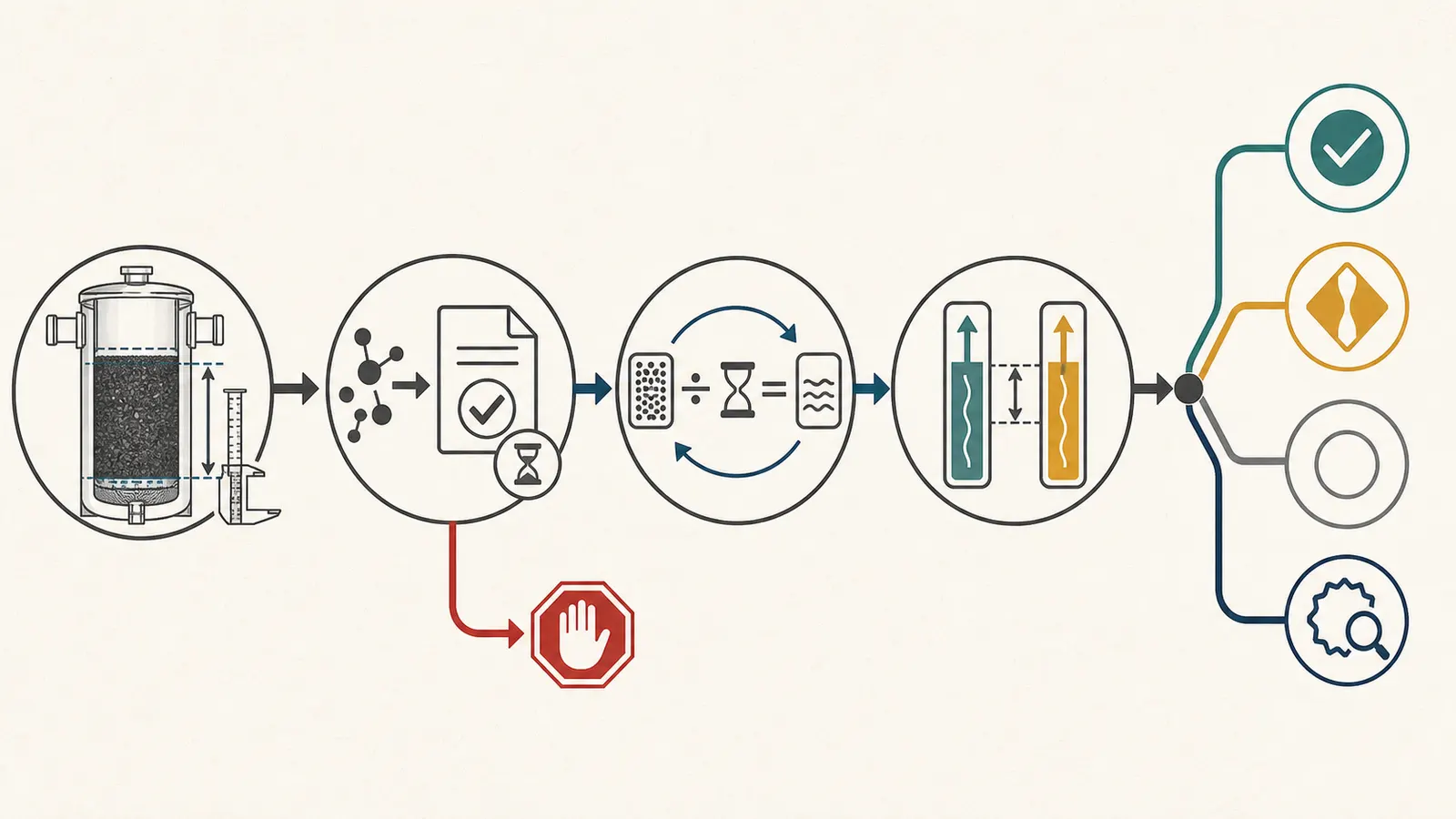
Use the following status logic after you calculate EBCT.
| Status | Conditions | Safest next action |
|---|---|---|
| Comparable hydraulic screen | Exact media volume, flow basis, vessel path, and a documented contaminant-specific EBCT basis are present | Compare price and installation scope only after the performance and maintenance fields also match |
| Flow-limited | The quoted bed volume meets the stated EBCT only below your observed or documented peak demand | Ask for a flow limiter, more media, storage, another train, or a redesign; do not assume pressure will remain acceptable |
| Arithmetic mismatch | The quote’s claimed EBCT does not equal the documented volume divided by documented flow | Ask for a corrected quote and explanation before authorization |
| Evidence missing | The quote names a contaminant but has no exact claim, test, pilot, comparable-system basis, capacity, or replacement trigger | Pause the purchase and obtain a certified lab result and qualified design review |
| Layout unclear | Series, parallel, bypass, and maintenance flow paths are not documented | Request a labeled piping diagram and valve-position operating plan |
| Water-quality mismatch | The proposed carbon is being used for a parameter the available evidence does not support, such as bacteria or nitrate | Stop treating EBCT as relevant; ask the health authority or qualified professional about another treatment path |
| Maintenance mismatch | No media-change method, sample locations, waste plan, or owner record is included | Require a written maintenance and verification plan before comparing totals |
Normalize two quotes line by line
Copy this checklist into your notes and mark each item “same,” “different,” or “unknown.” Two totals are not comparable when one proposal includes pretreatment, flow control, sample taps, disinfection, startup testing, media disposal, or future changeout and the other does not.
- Same target contaminant or contaminants, with the same units and concentration basis.
- Same treated-water target and same certification, pilot, or comparable-system evidence.
- Same carbon manufacturer, grade, media volume, and whether the volume is per vessel or total.
- Same vessel count, series or parallel layout, bypass path, and normal valve positions.
- Same design flow, peak-flow assumption, flow limiter, and pressure-drop condition.
- Same pretreatment for sediment, iron, manganese, chlorine, dissolved organics, or other chemistry.
- Same sample-tap locations and laboratory plan for raw, intermediate, and treated water.
- Same breakthrough trigger, media capacity, changeout interval basis, and who pays for media.
- Same backwash or drain destination, septic or sewer constraints, and waste handling.
- Same startup flushing, disinfection, commissioning, and post-install test responsibilities.
- Same space, access, connection, support, pressure rating, temperature, and service-clearance assumptions.
- Same warranty, exclusions, monitoring responsibilities, and change-order terms.
Ask the seller to fill every “unknown” in writing. A blank is not neutral when the missing field controls whether the carbon sees the right flow, the right water chemistry, or the right maintenance.

What to send with a professional review request
Prepare one compact evidence packet:
- The latest raw-water laboratory report, including sample point and date.
- Any post-treatment result, with the exact treated-water sample point and date.
- The complete quote, product data sheet, installation diagram, and manual.
- Media manufacturer, grade, fill quantity, vessel model, and normal flow direction.
- Your timed-flow notes, fixture locations, repeats, and any observed pressure-cycle behavior.
- Inlet/outlet pressure readings if gauges are already installed and visible safely.
- Pretreatment equipment, maintenance records, bypass status, and previous carbon changeouts.
- The questions you want answered: EBCT basis, peak flow, breakthrough trigger, sample plan, waste handling, and what happens during maintenance.
The professional should be able to state what the quote assumes and what would cause the design to change. For a health-sensitive contaminant, ask who will verify the treated result, which laboratory will be used, and what water uses remain acceptable while the result is unknown.
8. Plan maintenance and verification before purchase #
A carbon tank is a continuing treatment obligation. Connecticut DPH says media can channel, become saturated, and reach breakthrough; it recommends manufacturer-directed maintenance, regular media changes, and keeping service records. It also notes that maintenance frequency varies with filter size, household water use, contaminant concentration, and overall water quality. (Connecticut’s GAC maintenance guidance)
Put these fields in the quote or owner record:
| Record | At installation | During ownership |
|---|---|---|
| Raw-water result | Compound, concentration, method, sample date | Repeat when the lab, health authority, or plan requires |
| Treated-water result | Startup result from the correct downstream point | Repeat at the documented frequency and after changeout |
| Flow | Commissioning flow and any limiter setting | Record unusual demand or changes in pressure/flow |
| Pressure | Normal inlet/outlet readings and differential at the stated flow | Watch for a trend only if gauges are already installed and readable safely |
| Carbon | Grade, amount, vessel order, installation date | Record media change date, amount, supplier, and disposal route |
| Breakthrough | Target concentration or other replacement trigger | Record the observation, sample, and action that followed |
| Pretreatment | Equipment and baseline condition | Record cartridge, media, oxidant, or other service separately |
| System state | Normal flow path, bypass status, sample-tap labels | Record every authorized valve or vessel configuration change |
Connecticut DPH recommends comparing untreated and treated water at a state-certified laboratory after installation and says that, for two filters in series, pre-, mid-, and post-filtration samples can help identify service needs or breakthrough. (Connecticut’s post-installation testing guidance) That is a strong model for a homeowner record, but the actual sampling method, frequency, and exposure response should follow the contaminant-specific plan and local requirements.
Do not open a vessel or handle spent carbon to “check” whether it is exhausted. Spent media may contain the chemicals removed from the water, and disposal requirements can depend on the contaminant and concentration. Connecticut DPH specifically advises asking about waste handling before choosing a GAC system. (Connecticut’s GAC waste-handling guidance) Have the installer or qualified service provider document media changeout, flushing, disinfection, and disposal.
The final decision is therefore not “Does this tank have enough minutes?” It is:
documented media volume
      + documented flow path and peak flow
      + a contaminant-specific EBCT and performance basis
      + pressure, pretreatment, and maintenance compatibility
      + a sampling and breakthrough response plan
      = a quote that can be responsibly compared
If one of those terms is missing, the correct output is not a confident yes. It is a documented follow-up question, a safer temporary water-use decision when health risk is possible, and a review by the certified laboratory, health authority, manufacturer, or qualified water-treatment professional who can supply the missing evidence.
Cite this guide
Brictale. “Whole-House Carbon Filter EBCT Calculator: A Quote-Check Worksheet.” Published 2026-09-03; updated 2026-09-03.
https://brictale.com/water/filtration/whole-house-carbon-filter-ebct-calculator · Read the Markdown version
Sources and scope
Evidence behind this page
- EPA defines EBCT as empty-bed volume divided by volumetric flow rate and states that the minimum EBCT varies with the contaminant, required removal percentage, GAC type, and other influent characteristics such as competing chemical species; EPA says EBCT is best determined from pilot studies or comparable GAC experience for similar influent water.
EPA's GAC engineering model documentation, especially the contaminant-removal and EBCT discussion on pages 40–42; it supports the formula and the screening limitation, not a universal homeowner target.
Accessed · Link to this claim - EPA's GAC model identifies contaminant, design and average flow, carbon life, removal requirements, number of contactors in series, bed depth, and contactor dimensions as design inputs.
EPA's GAC model input-sheet documentation on pages 36–38; these are engineering-model inputs and do not establish that every residential installation needs every listed component.
Accessed · Link to this claim - EPA says GAC service life varies with site-specific conditions and carbon quality, including carbon type, surface area, pore-size distribution, and surface chemistry; theoretical isotherm calculations do not account for all factors such as fouling, other organics, and carbon losses.
EPA's carbon-life discussion on pages 38–41; it supports a request for site-specific evidence and does not predict a particular home's replacement interval.
Accessed · Link to this claim - EPA describes multiple GAC vessels in series as a lead/lag arrangement in which the first vessel is a roughing vessel and later vessels are polishing vessels; when the roughing vessel is spent, media replacement and vessel repositioning can extend overall bed life compared with a single vessel of similar total bed volume.
EPA's pressure-GAC series-operation discussion on pages 42–43; the described arrangement is a design concept, not a blanket recommendation for every private well.
Accessed · Link to this claim - EPA's Drinking Water Treatability Database identifies breakthrough, EBCT, and design flow rate as primary factors in determining GAC contactor volume and explains that longer EBCT can be achieved by increasing bed volume or reducing flow.
US EPA — Drinking Water Treatability Database: Activated Carbon
The EPA Treatability Database page for activated-carbon treatment; the page is a technical reference and does not certify a residential product or set a private-well health endpoint.
Accessed · Link to this claim - Connecticut Department of Public Health says GAC is commonly used for chemical contaminants and taste and odor, but its private-well guidance does not consider GAC effective for microorganisms, some metals, or nitrates; it also says effectiveness depends on the media type, contaminant type and concentration, and filter size.
Connecticut Department of Public Health — Granular Activated Carbon Treatment of Private Well Water
Connecticut DPH private-well guidance dated May 19, 2026; its contaminant examples are state guidance and must not be broadened into a universal treatment claim.
Accessed · Link to this claim - Connecticut DPH says channels can form in GAC media and decrease effectiveness, and that GAC systems require manufacturer-directed maintenance and media replacement; it notes that replacement frequency varies with filter size, household use, contaminant concentration, and overall water quality.
Connecticut Department of Public Health — Granular Activated Carbon Treatment of Private Well Water
Connecticut DPH private-well guidance dated May 19, 2026; it supports a maintenance and breakthrough evidence request, not a universal replacement calendar.
Accessed · Link to this claim - Connecticut DPH recommends testing untreated and treated water at a state-certified laboratory after installation, comparing the results, and testing annually or more frequently when untreated contaminant levels are high; for two filters in series it describes pre-, mid-, and post-filtration sampling to identify service needs or breakthrough.
Connecticut Department of Public Health — Granular Activated Carbon Treatment of Private Well Water
Connecticut DPH private-well installation and water-testing guidance; the testing frequency is guidance, not a national rule, and local requirements may differ.
Accessed · Link to this claim - New York Department of Health defines EBCT for GAC as empty-bed volume divided by design flow rate and notes that different raw materials produce GAC with different properties, including affinity for a specific contaminant.
New York State Department of Health Bureau of Water Supply Protection recommendations, version 1.0 dated April 26, 2021; the document is written for reviewed GAC installations and is not a national residential design standard.
Accessed · Link to this claim - New York Department of Health recommends small-scale or pilot testing to determine GAC design parameters, or a documented justification based on systems with similar water quality, contaminant concentrations, and treatment requirements; it lists media selection, EBCT, adsorption competition, and anticipated lifespan among the minimum design topics.
New York State Department of Health recommendations for GAC design review; the recommendation is used here to define questions for a quote, not to impose a New York approval process nationwide.
Accessed · Link to this claim - New York Department of Health says at least two contactors should be provided unless approved otherwise for the reviewed public-water-system context, and it says anticipated GAC head loss, downstream pressure, pressure gauges, flow meters, and sample taps should be addressed in the design and operating plan.
New York State Department of Health recommendations for reviewed GAC installations; the two-contactor recommendation and local approval language are not presented as a national private-well requirement.
Accessed · Link to this claim - New York's Appendix 75-B.2 for activated-carbon treatment systems serving individual water supplies specifies a three-minute minimum EBCT and says this should be achieved with at least two equal-size units in series, while also addressing flow control, sampling, pressure gauges, pretreatment, disinfection, and component pressure limits.
New York Codes, Rules and Regulations — Appendix 75-B.2 Activated Carbon Treatment Systems
A New York state-specific appendix effective December 1, 1990; it is included only as an example of a local or program-specific rule and must not be generalized to all US homes.
Accessed · Link to this claim - EPA recommends annual private-well testing for total coliform bacteria, nitrates, total dissolved solids, and pH, additional testing when other contaminants are suspected, and use of laboratories certified for drinking-water testing.
US EPA — Protect Your Home's Water
EPA consumer guidance for private-well owners; the listed annual panel is a baseline recommendation and does not identify every contaminant relevant to every site.
Accessed · Link to this claim - NSF says certification to an NSF/ANSI standard or protocol does not mean a treatment system reduces all possible contaminants; homeowners should verify certification for the specific contaminant of concern, and NSF's reduction-claims guide lists whole-house systems for some claims but not others.
NSF — Standards for Water Treatment Systems and Contaminant Reduction Claims
NSF consumer guidance on voluntary residential treatment standards and claim-specific listings; it supports exact-claim verification, not a conclusion that a particular product is certified.
Accessed · Link to this claim