How to Prepare a New-Home Building-Envelope Materials Compatibility Register Before Ordering
Use a layer-and-interface worksheet to verify envelope materials, accessories, sequence, responsibility, evidence, warranties and open approvals before ordering.
The short answer
Before ordering, make one register row for every envelope layer and interface—not just each product. Record the exact revision, substrate, adjacent materials, compatible accessory, sequence, exposure limit, code or evaluation evidence, responsible person, inspection record, warranty condition and unresolved question. Release only rows that are documented, assigned and verified; route structural, fire, vapor-control, hygrothermal and local-code questions to the architect, engineer, builder or building official.How to Prepare a New-Home Building-Envelope Materials Compatibility Register Before Ordering
Before ordering, make one register row for every envelope layer and interface—not just each product. Record the exact revision, substrate, adjacent materials, compatible accessory, sequence, exposure limit, code or evaluation evidence, responsible person, inspection record, warranty condition and unresolved question. Release only rows that are documented, assigned and verified; route structural, fire, vapor-control, hygrothermal and local-code questions to the architect, engineer, builder or building official.
1. Set the release rule before anyone orders #
Do not release a new-home envelope package until every material and critical interface has a named decision owner, a traceable source, an installation sequence and a verification record; a familiar brand name or a visually plausible wall section is not enough.
This guide is for a United States single-family home at pre-order or pre-installation stage. “United States” is not a building jurisdiction. The applicable requirements are those adopted and enforced for the project by the responsible state, county or city authority—often a building department or code official—with any amendments, permit conditions and special requirements that authority applies. The current official ICC-ES ESR-1993 report identifies the named product, evaluated properties, code editions and conditions, but it is not an endorsement and does not prove unaddressed attributes or the performance of your complete wall. Its cover is reissued August 2024 and marked “Subject to renewal August 2026.” ICC-ES’s official report directory says downloadable reports remain valid when a re-examination date has passed if they are under re-examination or covered by a legacy extension; that status note does not make the report a local approval. The project team must still confirm the locally adopted code, permit conditions and the authority’s acceptance of this product and use.
The homeowner’s job is coordination and evidence collection, not remote approval. The architect or engineer owns the design assumptions and any required structural, fire, vapor-control or hygrothermal analysis. The builder owns procurement coordination, means and methods, subcontractor scope and construction quality unless the contract allocates those duties differently. The siding, masonry, roofing, window, insulation and waterproofing trades own their work within the approved documents and must identify conflicts before covering a preceding layer. A third-party energy rater, program verifier or inspector has only the authority assigned by the program, contract or jurisdiction.
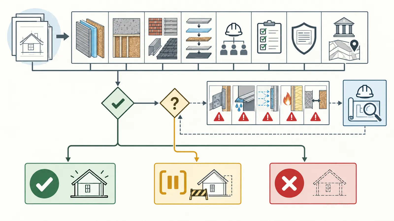
The release decision has three possible outcomes:
- Release: the exact product and revision are identified; adjacent materials and accessories are documented; the sequence can be built; the applicable code or evaluation path is assigned; a responsible person has accepted the item; and verification evidence is defined.
- Release with a bounded hold: materials that are unlikely to change the unresolved question may be ordered, but the affected interface, accessory, quantity or installation cannot be released. The purchase order must say what is excluded and who must approve it.
- Do not release: a missing substrate, unknown product revision, unsupported sealant, unverified attachment, missing flashing, incompatible sequence, unassigned code question or warranty condition could change the package. Stop that package until the question is answered in writing.
The point is not to prove that every brand works with every other brand. The point is to show why the selected combination is acceptable for this project—or expose the exact question that prevents a safe order. That distinction protects the schedule: a clear “not yet” on one interface is more useful than a broad order that later forces demolition, substitution or a design change. For the broader material-method decision around this register, continue with materials planning and systems after the open interface has an owner.
For a homeowner, the register is most useful when it changes a conversation into a traceable decision. Before approving a purchase, ask the builder to point from the purchase-order line to the corresponding register row, drawing detail and verification record. If the row depends on a pending window dimension, attachment calculation, manufacturer response or local interpretation, mark that dependency instead of hiding it in an email thread. A bounded hold can keep unrelated procurement moving, but it must name the excluded material and the event that releases it. This makes the next handoff visible: the person answering the question knows what evidence is needed and the homeowner knows what remains undecided.
The compact originality brief
Current answers are fragmented across DOE and EPA enclosure guidance, code-evaluation reports, and individual manufacturer manuals, warranties and compatibility FAQs. The missing decision is whether the selected materials can be released as one coordinated package before purchase. The original contribution is the Envelope compatibility register and pre-order release gate: a source-comparison worksheet with a row for every layer and interface, followed by an illustrative two-wall-package review and a sensitivity showing how exterior insulation thickness and cladding weight change attachment and review needs.
You can check the contribution by asking another person to recreate the same result from the same product revisions. They should be able to identify every material, see which source supports each statement, find each unresolved owner and reproduce the example’s calculations. If they cannot, the register is incomplete. This is a modeled editorial tool, not collected field data, laboratory testing, a code document or professional design approval.
What this register does not decide
It does not remotely select a wall assembly, size framing, calculate wind or seismic loads, approve a masonry veneer, select a fire-resistance-rated assembly, determine condensation risk, decide a vapor-retarder class, approve a window installation, or replace a permit review. Those decisions depend on the project’s drawings, climate, exposure, geometry, materials, code edition, engineering and local authority.
It also does not turn a manufacturer’s word “compatible” into a whole-system warranty. A product page may describe one item’s properties. A warranty may cover a named product or a named set of accessories. An evaluation report may cover a product under listed conditions. None by itself covers every adjacent product, fastener, substrate, exposure duration and installer decision. The register keeps those claims separate.
2. Freeze the inputs that make compatibility meaningful #
Compatibility cannot be reviewed until the project team freezes the wall geometry, climate and code inputs that determine what each product must do and what can touch it.
Start a register only after the design team can issue a coordinated wall section, even if it is marked “for procurement coordination” rather than “issued for construction.” The section should identify the exterior cladding, drainage or ventilation space, water-resistive barrier, sheathing, framing, insulation, interior air or vapor control layer, interior finish, openings, base, top, corners, roof-to-wall conditions and penetrations. A list saying “fiber cement over insulation over WRB” is not enough. It omits the support plane, fastener path, drainage path, flashing, transitions and responsibility. If those inputs are still being chosen, return the handoff to the home design and layout brief before treating the register as a purchasing record.
Record these inputs on the first page of the register:
| Input | What to record | Why it changes the decision | Owner to confirm |
|---|---|---|---|
| Project jurisdiction | State; county if relevant; city or town; building department; adopted code edition and amendments; permit status | A model code, program checklist or ESR is not automatically the local rule | Homeowner with architect or builder; building official for interpretation |
| Climate and exposure | IECC climate zone if used by the design; moisture zone; wind-driven-rain exposure; wind, wildfire, snow or marine concerns where applicable | Vapor control, drying, fire provisions, flashing and exposure limits are not universal | Architect or engineer |
| Wall geometry | Framing spacing; sheathing; wall height; corners; offsets; parapets; roof and foundation transitions | Determines lap, fastening lines, movement and continuity | Architect or engineer |
| Openings | Window and door type, flange or non-flange condition, sill, head, jamb, rough-opening size and sequence | Opening flashing is an interface, not an accessory afterthought | Window supplier and builder, reviewed by design lead |
| Cladding | Product family, profile, weight per area, joint pattern, attachment method, finish and clearances | Changes furring, fastener, joint-flashing and substrate needs | Architect, cladding trade and builder |
| Exterior insulation | Exact product; thickness; facer; board dimensions; compressive or attachment guidance; number of layers | Changes cladding support depth, screw length, thermal and drainage geometry | Architect or engineer with insulation and cladding trades |
| Interior control layers | Air barrier, vapor retarder or smart membrane, location, penetrations and service cavity | Air leakage and vapor diffusion are different control problems | Architect or enclosure consultant |
| Procurement state | Approved product, acceptable alternate, lead time, storage location, lot or revision record | A substitution can change warranty, accessory and sequence | Builder and homeowner |
The DOE distinction between air barriers and vapor retarders is a useful guardrail. An air barrier limits air-transported moisture; a vapor retarder reduces vapor diffusion. Whether, where and how a vapor retarder is used depends on climate and construction. Therefore, do not put “vapor barrier” in a purchasing list as if it were interchangeable with “housewrap,” and do not infer the needed interior layer from a product’s water-resistance label. The design professional must resolve the assembly’s control-layer strategy.
Record the physical facts, not marketing categories
For each selected item, record the exact product name, model or grade, dimensions, thickness, facer or coating, package unit, manufacturer document title, document revision or publication date, access date, and any identified lot or batch information. A product family can include several housewraps, tapes, sealants or flashings with different conditions. “Brand X tape” is not a traceable item.
For each adjacent pair, record the actual contact or separation. “Insulation next to WRB” may mean direct contact, a drainage mat between them, a taped insulation face, or a cladding attachment cavity. “Cladding over insulation” may mean screws through furring into studs, clips into structure, masonry ties, a proprietary rail or an assembly not yet designed. Each is a different interface.
Use units consistently. Record insulation in inches or millimeters, cladding weight in pounds per square foot, furring in inches, fastener diameter and embedment in the units used by the source, and exposure time in days. Do not convert a manufacturer’s threshold silently. If the drawing uses millimeters and a manual uses inches, show both and retain the original value in a notes field.
Separate five kinds of evidence
Every row should label the evidence type. This prevents a common category error in which a product test result is treated as a code approval or a warranty term is treated as an installation instruction.
- Physical fit: the layers can occupy the available space without crushing, buckling, blocking drainage or misaligning the opening.
- Documented compatibility: the manufacturer’s instruction, technical bulletin, detail or FAQ specifically permits the contact, accessory or sequence under stated conditions.
- Code or evaluation evidence: the local authority’s adopted provisions, an approved alternate path, or an evaluation report covers the named product and use. The current official ICC-ES ESR-1993 report illustrates the limit: its scope applies to the named DuPont Tyvek ThermaWrap LE product and listed conditions, not to every WRB or every wall. Its cover still shows “Subject to renewal August 2026,” while the ICC-ES report-directory status note says downloadable reports remain valid when a re-examination date has passed if they are under re-examination or covered by a legacy extension. Treat that as report-directory status, not as a blanket local approval; the project team must confirm the applicable authority and use.
- Verification evidence: a photograph, delivery record, marked-up drawing, inspection checklist, fastener log, product label or signed trade confirmation that shows the work or material matches the decision.
- Warranty evidence: the actual warranty document, term, covered property, listed accessory set, exclusions and required installation conditions.
Mark any conclusion supported only by the first category as open. A board that fits between two layers may still be unsupported, have the wrong perm or facer, require a different fastener, violate an opening detail or fall outside the warranty.
3. Build the layer-and-interface worksheet #
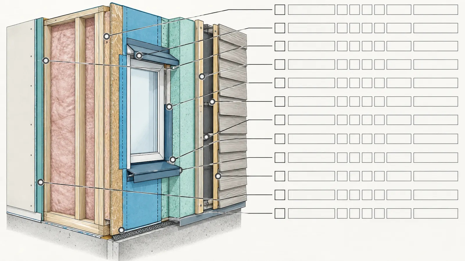
The usable worksheet has one row for each layer and one additional row for each place where a layer changes, stops, is penetrated or meets another material.
Copy this structure into a spreadsheet or project-control document. The “status” is deliberately strict: green means documented and assigned, amber means bounded but not releasable at the affected interface, and red means an unresolved condition can change the order or installation.
| ID / layer or interface | Exact product and revision | Substrate and adjacent materials | Code / ESR / manufacturer evidence | Compatible accessory and sequence | Exposure or use limit | Responsible person | Verification record | Warranty condition | Unresolved risk / next handoff | Status |
|---|---|---|---|---|---|---|---|---|---|---|
| L1 structural frame and sheathing | Species or framing system; sheathing panel and thickness; drawing revision | Studs, headers, OSB or plywood, openings | Structural drawings and locally adopted requirements; APA moisture guidance | Frame, sheath, dry-in, inspect before WRB | Jobsite wetting and storage limits from supplier | Architect or engineer; builder | Framing and sheathing inspection, panel labels, photos | Panel maker’s exposure and installation conditions | Confirm moisture condition and hold points with builder | Amber until inspected |
| L2 WRB field | Exact WRB, roll width, document revision | Sheathing or approved insulation face; cladding side | Product manual; DOE drainage-plane guidance | Approved tape or sealant; install shingle-style and integrate with flashing | Product’s stated uncovered time, UV and substrate limits | WRB trade, builder | Roll labels, seam and lap photos before cladding | Product-only or system warranty, exact accessories | Confirm product is the specified family, not a substitute | Amber until documents match |
| L3 WRB seams and corners | Same WRB plus named tape or sealant | WRB to WRB, corners and transitions | Manual and chemical-compatibility bulletin | Tape, primer or sealant named by manufacturer; clean and dry substrate | Temperature, dust, moisture and cure limits | WRB trade | Lot numbers, temperature/weather note, close-up photos | Listed accessory and installation method | Ask manufacturer if mixed-brand sealant is proposed | Red if unnamed |
| L4 base, top and roof-to-wall | Flashing type and membrane revision | WRB, foundation, roof underlayment, cladding | EPA water-managed wall checks; details and local code | Lower layer receives upper layer; provide outward drainage; sequence before cladding | Exposure and compatible substrate from each product | Builder and waterproofing or roofing trade | Detail photo before cover; marked-up section | Warranty may require specified flashing | Design lead resolves laps and transitions | Red if no detail |
| L5 windows and doors | Manufacturer, model, flange condition and installation guide | Rough opening, sill, jamb, head, WRB and flashing | Window manual, WRB manual and local approved detail | Sill pan or membrane, jamb/head flashing, backdam or sealant as specified | Opening size, temperature and temporary exposure limits | Window installer; builder coordinates WRB trade | Sill/head/jamb photos and product labels | Window and WRB warranty conditions | Window supplier and architect approve interface | Red until sequence is issued |
| L6 penetrations | Each vent, pipe, light, hose bib, electrical box and bracket | Penetration, WRB, flashing and cladding | Product detail and local electrical/plumbing/mechanical requirements | Boots, collars, sealant or flashing; install before or after WRB as detailed | Movement, temperature, UV and service access | Relevant trade; builder coordinates | Penetration map and photos | Sealant/accessory conditions | Assign every penetration to one trade | Amber if mapped |
| L7 exterior continuous insulation | Exact board, thickness, facer and revision | Sheathing or WRB; furring or clips; cladding | Insulation guide; energy and fire design; ROCKWOOL attachment guidance | Mechanical attachment, washers, furring, long screws or engineered clips | Board support, moisture and temporary exposure limits | Architect or engineer; insulation and cladding trades | Board labels, layout, fastener log and photos | Warranty and tested assembly conditions | Recheck when thickness or cladding weight changes | Red if support path absent |
| L8 furring / cladding support | Size, species or gauge; spacing; rail or clip model | Insulation, sheathing, studs, cladding | Structural attachment design and product guide | Screws penetrate designed framing; maintain drainage cavity | Wind, gravity, corrosion, edge distance and movement | Engineer or architect; builder | Layout, screw type and embedment record | Cladding system conditions | Engineer resolves load path and corrosion class | Red until designed |
| L9 cladding field | Exact cladding, profile, finish and installation revision | Furring or structural backup, WRB and joint flashing | Cladding manual; local code; Hardie lap-siding guidance where applicable | Starter, joints, trim, flashing and fasteners in sequence | Clearance, joint, finish and weather limits | Cladding trade | Course, joint and flashing photos | Cladding warranty’s substrate and installation terms | Confirm local flashing dimension and substrate | Amber until mock-up |
| L10 masonry or stucco transition | Veneer/stucco system and accessories | WRB, bond-break drainage plane, lath, shelf angle, weeps | EPA wall checklist, engineered/detail package | Bond break, flashing, weeps or screed in sequence | Mortar, curing, drainage and corrosion conditions | Masonry/stucco trade; architect | Pre-cover photo and inspection record | Assembly and manufacturer conditions | Design lead resolves non-structural vs structural masonry | Red if bond break absent |
| L11 interior air / vapor control | Exact membrane, coating or gypsum strategy | Interior finish, framing, insulation and penetrations | Climate-specific design and adopted code; DOE air/vapor guidance | Sealants, tapes, gaskets and service cavity; sequence before closing | Climate, drying direction and penetrations | Architect or enclosure professional; builder | Air-seal checklist and photos before drywall | Product and assembly conditions | Professional resolves condensation risk | Red if merely labeled “vapor barrier” |
| L12 cladding-to-roof and base handoff | Metal, membrane, drip edge, kickout or termination products | Roof, wall WRB, siding, gutters, foundation | Roof and wall details; EPA flashing checks | Install drainage from upper to lower layer; coordinate gutter discharge | Rain, snow, sealant and corrosion limits | Roofing and siding trades; builder | Handoff photo and checklist sign-off | Each product’s termination conditions | Builder schedules joint inspection | Red if trades install independently |
| L13 storage and protection | All products and packaging | Ground, weather, sunlight and site traffic | Each product’s storage and handling instructions | Store flat or supported; protect from water and contamination | Exposure limit starts at delivery if product says so | Builder or site superintendent | Delivery photos, dates and damaged-material log | Warranty may exclude damaged or misused material | Quarantine damaged or wet stock | Amber until logged |
The row is not complete when a URL is pasted into it. Add the exact claim from the document, the page or section, the date checked and the condition that makes the claim applicable. If a PDF changed between design and ordering, preserve the reviewed copy in the project record and recheck the current revision. Do not overwrite the earlier decision without recording the change.
The interface inventory that people forget
Walk the wall section with a highlighter and mark every interruption. Typical omissions include the bottom of wall, window sill and head, door threshold, roof-to-wall step, parapet, deck ledger, porch roof, outside and inside corners, change from siding to masonry, utility penetrations, hose bibs, exterior outlets, light fixtures, exhaust terminations, dryer vents, refrigerant lines, satellite brackets, railings, gutters and cladding butt joints.
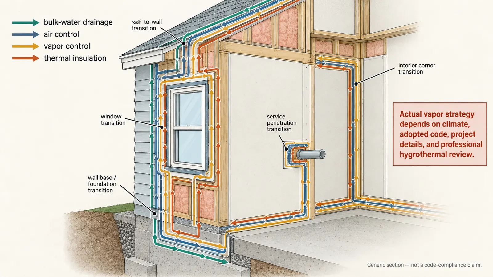
The DOE drainage-plane guidance says the WRB should be continuous behind cladding, with seams sealed, and should lap over flashing around openings, penetrations, the wall top and base. That is a coordination rule for the register, not a universal detail dimension. The practical translation is: if you cannot draw the water path from the highest exposed joint to the exterior without crossing an unassigned trade’s work, the row is not green.
For non-structural masonry, stucco or another cladding that can hold water against the wall, add a separate bond-break or drainage-plane row rather than hiding it in “WRB.” EPA’s Indoor airPLUS Version 2 checklist lists a continuous WRB behind cladding, a bond-break drainage plane for non-structural masonry, flashing or drainage at horizontal interruptions and wall bottoms, weeps for masonry or a weep screed for stucco, and fully flashed windows and doors. Indoor airPLUS is a voluntary program, not automatically the project’s code, but its checklist is a useful completeness test.
4. Review each compatibility question in the right order #
Review the register from structure to weather exposure, then from water control to air and vapor control; do not approve a top layer while the support and drainage path beneath it remain uncertain.
Use this review order for every row and interface:
- Can it be built in the stated geometry? Check thickness, gaps, offsets, opening sizes, furring depth, fastener length and access. Measure from the coordinated section rather than from a product photograph.
- Can the substrate accept it? A tape, membrane, flashing or fastener may require clean sheathing, a particular facer, dry concrete, wood framing or a specified backing. Record “substrate not confirmed” as an open issue.
- Is the contact documented? Find a manual detail, technical bulletin, compatibility table, warranty condition or written manufacturer response for the proposed adjacent material. If the document says “compatible with standard sealants,” identify whether that means a class of products, a named list or a surface condition.
- Does the assembly drain and dry? Trace rainwater, incidental water, construction moisture and vapor movement. The APA moisture guidance identifies missing or improper flashing, WRB installation, wall intersections and penetrations as important contributors to wall water damage, and says WRB lapping, sealing and integration with flashing are critical. It also notes that rain-screen construction can add protection in wind-driven-rain areas; that does not by itself determine cavity depth or screen design.
- Can the next trade install its layer without destroying the previous one? A screw through a membrane, a masonry tie through a flashing, a window fin installed after the WRB or a furring strip blocking drainage is a sequence issue. Write the order in verbs: sheath, inspect, flash sill, install window, integrate WRB, flash head, install insulation, install furring, inspect cavity, install cladding.
- Does the evidence cover this exact product and use? A report for Tyvek ThermaWrap LE does not automatically cover Weathermate Plus. A product page for a Hardie weather barrier does not automatically approve a mixed-brand flashing. A board insulation guide’s baseline fasteners do not replace the attachment design for heavy cladding.
- Who can accept the decision? Assign the homeowner for scope and budget choices, the builder for coordination and procurement, the design professional for design and performance, the relevant trade for installation feasibility, the manufacturer for a product-specific response, and the building official for jurisdictional interpretation or approval when required.
- What record proves completion? Choose the record before work is covered: photo with a location reference, marked-up detail, product label, delivery docket, fastener log, moisture reading by a qualified person, inspection report or signed trade checklist.
Read manuals for conditions, not slogans
Start at the “scope,” “limitations,” “substrate,” “installation,” “facade considerations,” “chemical compatibility,” “storage,” “exposure,” “warranty” and “technical support” sections. Search the document for the exact adjacent material and the words “not,” “only,” “approved,” “minimum,” “maximum,” “must,” “shall,” “except,” “compatible,” “cover,” “exposure” and “penetrate.” Capture the surrounding condition, not just the favorable sentence.
DuPont’s March 12, 2025 typical wall drawing is a good example of conditional evidence. It shows a residential wood-frame assembly with Tyvek WRB over Styrofoam XPS, OSB, studs with batt insulation, an interior vapor retarder where required and gypsum board. It calls for taped WRB joints, shows vertical seam overlap of 6–12 inches and a minimum 6-inch horizontal lap, and says the applicable installation guideline should determine the WRB for the cladding type. It also directs vapor-retarder use to applicable building codes and sealant questions to chemical-compatibility guidance. Treat these as inputs to a review, not as permission to copy the drawing into a different wall.
The manufacturer’s wording may deliberately stop short of whole-wall approval. James Hardie says in its weather-barrier product information that no exterior cladding prevents 100% of water intrusion and describes a suite of separate housewrap, Pro-Flashing, Flex Flashing and Seam Tape products. Its page also says availability may be limited by location. A package using a James Hardie cladding with another company’s WRB therefore needs a project-specific interface review, even if both products are individually reputable.
Benjamin Obdyke’s HydroCorner FAQ says that product is compatible with most caulks, sealants and straight-flashing tapes and that a mechanical fastener is sufficient to hold it before sill flashing. The words “most” and “before sill flashing” matter. They do not mean every sealant, every tape or every sequence is approved. Put the proposed sealant and tape names in the row and ask for a written response if the combination is outside the named guidance.
Verify the control-layer logic separately
A wall can be rain-tight at the surface and still have an unresolved air or vapor strategy. The DOE guidance says a vapor retarder’s location and need depend on climate and construction, and recommends continuity and sealing to limit moist air entering a cavity. This is why the register needs separate rows for exterior water control, air control and vapor control, even where one product may perform more than one function.
The homeowner can ask the design professional to identify, in a section, the intended control layers and their transitions. Ask: Which layer is the water-resistive barrier? Which layer is the primary air barrier? Where is the vapor retarder, if any? How does each cross a window, roof, foundation, corner and penetration? Which layer must remain continuous after furring and services? What drying direction was assumed? What change would require hygrothermal review?
Do not answer those questions by comparing perm numbers alone. DuPont lists a 5 perm minimum water-vapor transmission rating for Weathermate Plus Housewrap, but that product fact does not determine the whole wall’s vapor profile. A product’s permeability, the sheathing, insulation ratio, interior finish, climate and air leakage all interact. Record the number as a product input and let the design professional decide how it is used.
5. Coordinate attachment, weight and the construction sequence #
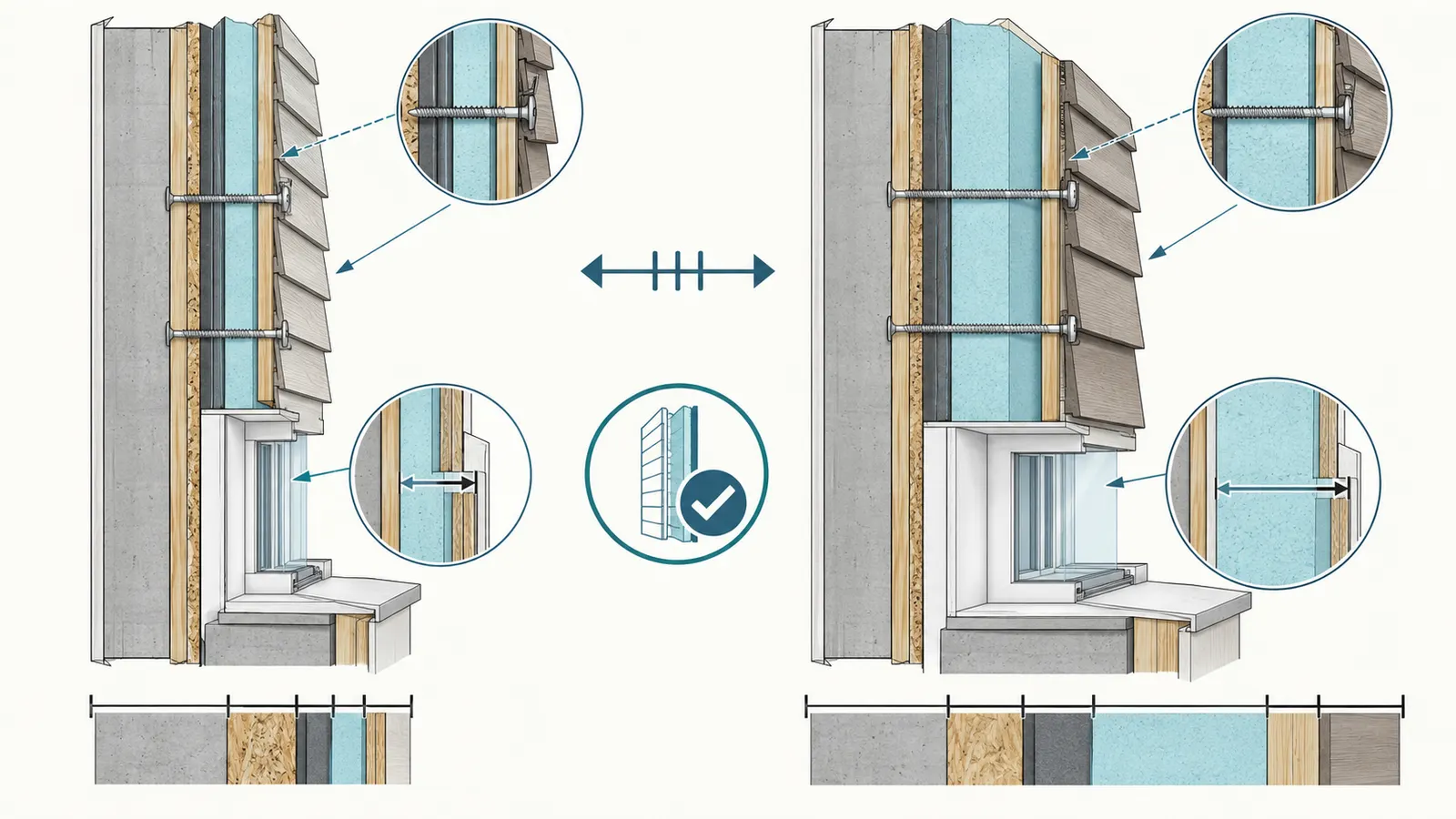
Treat exterior insulation and cladding support as a load-path and sequencing decision; increasing insulation thickness or cladding weight can change fastener length, spacing, furring, engineering review and the number of trades involved.
This is the interface most likely to be falsely marked “compatible” because the boards physically fit. A cladding system has gravity, wind, movement, corrosion and edge-distance demands. The support may need to transfer loads through insulation and sheathing into studs, blocking, masonry or an engineered clip. The WRB, flashing and drainage cavity must remain functional while that support is installed.
ROCKWOOL’s Comfortboard 80 residential guide recommends permanent mechanical attachment and mechanical fasteners with minimum 2-inch-diameter washers. It recommends at least five attachments per board when only mechanical fasteners or impaling pins support the board, but it also says requirements may vary when the boards are installed within a cladding attachment system. Put both statements in the register. The five-attachment baseline is not a substitute for the cladding attachment design.
ROCKWOOL’s official Board Insulation Attachment Guide organizes attachment around exterior insulation thickness, cladding weight, stud spacing, fastener diameter, embedment and strapping. It specifically states that long screws must penetrate framing members and that project-specific cladding loads affect specification. This gives the homeowner a practical change-control trigger: a change in board thickness, cladding mass or stud spacing reopens the attachment row.
Worked example: two illustrative wall packages
The following is an illustrative modeled example, not a recommendation, tested result, estimate of code compliance or professional design. Its purpose is to show how the register changes when one input changes. Assume a hypothetical two-story wood-framed home in the United States with 16-inch-on-center studs, OSB sheathing, a continuous exterior insulation layer, vertical furring over studs and a lap cladding. No wind pressure, seismic demand, fire rating, opening geometry, fastener withdrawal value, structural capacity or local amendment is supplied; therefore the attachment remains a professional review item.
Package A inputs
- Exterior insulation: 2 inches thick.
- Cladding: illustrative light-to-medium lap cladding, modeled at 4 pounds per square foot.
- Furring: a proposed 3/4-inch-deep vertical strip, subject to design confirmation.
- Sheathing: OSB, exact thickness not assumed.
- Fastener: proposed long screw, exact diameter and embedment not selected.
- WRB: an exact product must be selected; a brand family is not enough.
Package B inputs
- Exterior insulation: 5 inches thick.
- Cladding: illustrative medium-to-heavy cladding, modeled at 9 pounds per square foot.
- Furring: a proposed 3/4-inch-deep vertical strip, subject to design confirmation.
- All other assumptions remain the same.
The simplified geometric relationship for a first coordination check is:
minimum screw length for the proposed stack = insulation thickness + furring thickness + sheathing and finish allowance + required structural embedment + washer or head allowance
This formula only checks whether the screw can span the stack and reach the intended framing. It does not prove capacity, spacing, pull-through resistance, corrosion suitability, edge distance or code compliance. Let the unknown design allowance be A and required structural embedment be E.
For Package A, the known exterior stack before the unknown allowances is:
2.0 in insulation + 0.75 in furring = 2.75 in
So the coordination length is:
L_A = 2.75 in + A + E
For Package B:
5.0 in insulation + 0.75 in furring = 5.75 in
L_B = 5.75 in + A + E
The modeled thickness change alone is:
L_B - L_A = 5.75 in - 2.75 in = 3.0 in
The result is not “buy a screw three inches longer.” It is “reopen the attachment design because the fastener must cross three additional inches before reaching the same structural target, while the cladding load and the insulation support condition also changed.” The architect or engineer and the attachment or cladding manufacturer must select the actual system.
The register should show the sensitivity like this:
| Modeled input change | Direct coordination effect | Decision that reopens | What cannot be inferred |
|---|---|---|---|
| Insulation from 2 to 5 inches | Exterior stack grows 3 inches; screw path, furring alignment and opening returns change | Fastener length, embedment, strapping and window/door extension details | Capacity, wind resistance or code approval |
| Cladding from 4 to 9 lb/ft² | Gravity and wind-support demand may increase; joint and trim support may change | Attachment schedule, furring size, fastener diameter, backing and engineer review | That any particular screw or spacing is adequate |
| Same WRB but a different cladding | Facade guidance, exposure and accessory compatibility may change | WRB selection, seam treatment, flashing and warranty review | That a cladding-neutral drawing covers the new facade |
| Same cladding but mixed-brand flashing | Product contact and warranty evidence changes | Named compatibility response and warranty condition | That “standard sealant” means every product |
| Same layers but a window changes from flanged to non-flanged | Opening geometry and sequencing change | Sill, jamb, head and WRB integration detail | That the old window flashing detail transfers |
Use sensitivity to control substitutions. If a supplier says the 5-inch board is unavailable and proposes 3 inches, that is not necessarily a harmless saving. It may change energy calculations, window returns, screw lengths, furring, thermal bridges, cladding alignment and the interior or exterior moisture strategy. If the owner selects a heavier brick veneer instead of lap siding, the support path and drainage details may change. The next handoff is design review, not a purchasing preference.
Sequence the handoffs on a real wall
Write the construction sequence with a responsible person beside each verb. One possible coordination sequence, to be replaced by the approved project detail, is:
- The framing trade builds the wall and openings to the issued drawings.
- The sheathing trade installs and records the panel product, fastener pattern and any damaged or wet panels.
- The builder or design lead inspects the substrate and confirms that the specified WRB can be installed on it.
- The window supplier and installer confirm rough openings and the sill, jamb and head sequence before the WRB is covered.
- The waterproofing or window trade installs the sill flashing or pan, window and opening flashings as detailed.
- The WRB trade installs the field membrane, tapes or seals seams, and integrates it with opening and transition flashings.
- The builder records penetrations and confirms which trade owns each boot, collar, seal or patch.
- The insulation trade installs the exact board with the approved attachment method, preserving drainage and opening transitions.
- The engineer, architect or delegated inspector verifies the furring and attachment layout before cladding covers it.
- The cladding trade installs starter, joints, trim, flashing and field pieces according to the issued detail and product guide.
- The builder and design lead inspect bases, corners, openings, penetrations, roof-to-wall transitions and cladding joints before closeout.
The sequence may differ, especially with exterior insulation over a WRB, a self-adhered WRB, a non-flanged window or masonry veneer. The rule is not that one sequence is universal; the rule is that the team must choose a sequence and identify the handoff where one trade’s work becomes another trade’s substrate. Carry that approved sequence, inspection point and unresolved-risk owner into construction decision and inspection planning before the first covering trade starts.
6. Verify exposure, accessories, warranties and substitutions #
Order only the product-and-accessory combination whose exposure, storage, installation and warranty conditions are recorded for the actual project; a product’s standalone specification is not a system warranty.
Track temporary exposure from delivery, not memory
Temporary exposure is a schedule input. DuPont says Weathermate Plus Housewrap may remain uncovered for up to 120 days and lists product properties including a 5 perm minimum vapor-transmission rating. The same page says to review instructions and the safety data sheet and to contact a local DuPont Tyvek specialist before writing specifications. Record “up to 120 days” only in a row naming that exact product and revision. Do not copy it to another housewrap, to a taped XPS face or to an assembly with unprotected seams.
Ask the builder to record the date each exposure-sensitive layer is installed, the date it is covered, weather events, damaged areas and repair material. The safest interpretation of a manufacturer’s maximum is a limit, not a production target. If the cladding schedule may exceed the limit, ask the manufacturer and design lead for a written plan before ordering; do not assume extra tape or paint extends the period.
Storage deserves its own row because damage can happen before installation. For each product, record whether it must be kept dry, elevated, supported, wrapped, shaded or protected from traffic. Photograph deliveries before unloading if the contract makes the builder responsible for damage. Quarantine torn, crushed, wet or contaminated rolls and boards until the responsible supplier or design lead decides whether they may be used. The homeowner can document the condition; a qualified person should decide whether damaged material remains fit for the assembly.
Read a warranty as a boundary map
The DuPont U.S. residential warranty overview distinguishes a 10-year product-only water warranty for Weathermate Plus Housewrap with Weathermate accessory products from listed Tyvek wrap systems paired with specified DuPont self-adhered flashing and, for some systems, DuPont continuous insulation. The table also distinguishes product and labor coverage and water, air, thermal or drainage coverage. That is precisely why the register needs a warranty column.
For every warranty claim, record:
- named product and accessory set;
- covered property, such as water, air, thermal or drainage;
- term and start date;
- required installer or installation method;
- substrate and cladding assumptions;
- exclusions for damage, exposure, incompatible materials or alterations;
- documents the owner must retain; and
- the person who will request written clarification.
Do not say “the wall is under warranty” when the document covers only a product or named product combination. Do not say “mixed-brand accessories are fine” because one FAQ says “most” sealants are compatible. If the package departs from the named set, mark the warranty as not established until the manufacturer gives a written answer or the owner accepts the risk after professional review.
Make substitutions follow the same gate
The builder should not substitute an “equivalent” envelope product by brand category. A substitution request should show the original row beside the proposed row and compare:
| Comparison | Original | Proposed | Release question |
|---|---|---|---|
| Product identity | Exact model, thickness, facer and revision | Exact model, thickness, facer and revision | Is the proposed product covered by the same detail or report? |
| Control function | Water, air, vapor or thermal role | Claimed role | Does the wall’s control-layer strategy remain continuous? |
| Adjacent materials | WRB, tape, flashing, insulation and cladding | New adjacent set | Is contact documented for each interface? |
| Dimensions | Laps, thickness, returns and cavity | New dimensions | Do windows, doors, furring and trims still fit? |
| Attachment | Fastener, spacing, embedment and backing | New method | Has the load path been reviewed? |
| Exposure | Temporary cover, UV and storage | New limit | Does the construction schedule still work? |
| Warranty | Named product system and coverage | New coverage | Is the warranty preserved, narrowed or unknown? |
| Approval | Code, ESR or local acceptance path | Proposed path | Who must approve before purchase? |
A substitution is not complete when the builder initials it. The relevant design professional must accept design effects; the applicable trade must accept installation effects; and the homeowner should receive the change, price, schedule and warranty consequences. If the substitution changes a code, fire, structural or moisture-control assumption, route it through the project’s formal change process and local authority where required.
7. Diagnose common failure branches before they become orders #
When a register row fails, classify the failure by its missing decision, freeze the affected release, assign the right owner and carry the question to the next handoff with evidence attached.
Failure branch: the package names products but not revisions
Observe: “Housewrap,” “flashing tape,” “rigid mineral wool” or “Hardie siding” appears in the quote, but no model, thickness, facer, width or document revision is listed.
Interpretation: Physical category is known; compatibility and warranty are unknown. A family page may contain several products with different uses.
Do not infer: The most common product is the selected product, or the distributor will supply the same revision used in the drawing.
Safest next step: Builder requests a written submittal with exact SKUs or model names, dimensions, manuals, safety data sheets where relevant, current warranty and availability. Architect or engineer checks the substitution against the design. Homeowner holds the affected order.
Next decision: Accept the named item, accept a documented alternate, or redesign the interface.
Failure branch: the WRB is continuous on the elevation but stops at openings
Observe: The elevation looks wrapped, but window heads, sills, doors, utility penetrations, roof steps or base transitions are absent from the detail.
Interpretation: The field layer may be present while the drainage path is discontinuous.
Do not infer: Water will find its way out, or cladding will hide the gap without consequence.
Safest next step: Mark every opening and transition on the elevation. Use the DOE drainage-plane guidance as a completeness prompt, then obtain the project-specific details from the design lead and product manuals. Photograph the sequence before cover.
Next decision: Issue a coordinated detail and assign sill, jamb, head and transition work to named trades.
Failure branch: a sealant is called “compatible” without a product name
Observe: The scope says “use compatible caulk” or “standard sealant.”
Interpretation: Compatibility has not been tested against the actual membrane, flashing, insulation facer, substrate and environmental condition.
Do not infer: All polyurethane, silicone, acrylic or construction adhesives are interchangeable.
Safest next step: Record the exact sealant, primer and tape. Check the product-specific guidance and request a written manufacturer response for an unlisted combination. Check cure temperature, substrate cleanliness and movement conditions.
Next decision: Use a named approved accessory, revise the detail or document a qualified alternate.
Failure branch: the wall fits in section but the cladding has no load path
Observe: The section shows thick insulation and furring, but the order contains no attachment schedule, fastener design, stud layout or backing.
Interpretation: The thermal layer is selected before the cladding support has been designed.
Do not infer: Longer screws automatically provide adequate support, or insulation is structural simply because it is rigid.
Safest next step: Send the section, insulation thickness, cladding weight, stud spacing, wind and seismic design data, opening geometry and proposed furring to the architect or engineer and the attachment manufacturer. Use ROCKWOOL’s Board Insulation Attachment Guide to identify the variables, not to self-select a final schedule.
Next decision: Approve an engineered attachment path, change the insulation or cladding, or hold the package.
Failure branch: a code or ESR report is used as a blanket approval
Observe: A submittal includes an evaluation report, and the team says the wall is approved.
Interpretation: Evidence exists for a named product or condition, but its scope may not include the selected product, code edition, cladding, substrate or complete assembly.
Do not infer: The report replaces local review or covers neighboring products.
Safest next step: Highlight the report’s evaluation subject, code editions, properties and conditions. Confirm with the responsible design professional and the building official in the project’s actual city or county whether the proposed use follows an accepted path.
Next decision: File the report as supporting evidence, obtain an alternate approval, or redesign.
Failure branch: the interior layer is added late as “vapor barrier”
Observe: A late material list adds polyethylene, foil-faced board or another low-perm layer after the exterior wall is already selected.
Interpretation: The air and vapor strategy may be changing without a climate and drying review.
Do not infer: More vapor resistance always means a safer wall.
Safest next step: Reopen the control-layer row. Give the design professional the climate, wall layers, insulation ratio, interior finish, mechanical conditioning and penetrations. Ask for a written decision about the intended air barrier, vapor retarder and drying direction.
Next decision: Keep, relocate, change or omit the layer under the approved design.
Failure branch: trades own disconnected pieces of the same drainage path
Observe: The roofer installs step flashing, the siding trade installs WRB, and the window installer flashes openings, but no one owns the lap between them.
Interpretation: Each piece may be correct alone while the handoff is wrong.
Do not infer: The last trade on site will repair the interface.
Safest next step: The builder calls a pre-install coordination meeting with the marked-up section. Assign upper-over-lower laps, temporary protection, inspection timing and repair authority.
Next decision: Sign the joint handoff only after the assembled path is visible in photos or an inspection record.
Failure branch: the package relies on a voluntary checklist as code
Observe: Someone cites EPA Indoor airPLUS as if it were the city’s building code.
Interpretation: A program requirement and a local legal requirement have been conflated.
Do not infer: Certification requirements automatically apply to a non-certified home, or satisfying them guarantees permit approval.
Safest next step: Label the checklist “program evidence” and separately record the state, county or city code path. Use the EPA list as a quality-control prompt where useful.
Next decision: Confirm the program scope, then obtain local approval through the project’s design and permit process.
8. Close the gate and hand over a buildable package #
Release the envelope package only when the register, drawings, submittals, purchase order, inspection plan and open-risk log tell the same story; otherwise release only unaffected materials and keep the affected interface on hold.
The final owner review
Before signing an order, the homeowner should be able to answer these questions in plain language:
- What exact material is being bought, in what unit and quantity, and which revision was reviewed?
- What is each product’s job: structure, water control, air control, vapor control, thermal control, drainage, support, finish or protection?
- What touches it on each side, and is the contact documented or merely assumed?
- What is the substrate at every interface, including around openings and transitions?
- Which accessory, tape, sealant, fastener, flashing, furring or trim is required?
- What must happen first, what must be inspected, and what can cover the work?
- Who owns each action: homeowner, architect, engineer, builder, trade, manufacturer or building official?
- What exact evidence will prove completion?
- What does the warranty cover, and what does it not cover?
- What local rule or permit condition still needs confirmation from the project’s actual authority?
- If the material changes, which rows and drawings reopen automatically?
- What is the next decision after this row is accepted?
If an answer is “the builder knows,” ask for it in the register or approved drawing. The purpose is not distrust; it is to make the handoff survive a person change, a delayed shipment or a substitution.
Release checklist
Use this checklist as a decision record, not as an official inspection or code form:
- Project state, county and city or town are recorded, with the responsible building authority identified.
- Adopted code edition, amendments and permit conditions are assigned to the design or permit lead.
- Climate, wind-driven-rain exposure and other design conditions relevant to the enclosure are recorded by the design professional.
- Coordinated wall sections show structure, sheathing, WRB, flashing, insulation, cavity, cladding, interior control layers, openings and transitions.
- Every layer has an exact product, thickness or dimension, revision, supplier and storage condition.
- Every interface has named adjacent materials, substrate, accessory and installation sequence.
- WRB continuity is traced at bases, tops, corners, openings, roof-to-wall joints and penetrations.
- Masonry, stucco or other non-structural veneer includes its bond-break or drainage-plane decision where applicable.
- Exterior insulation and cladding support have a documented load path and professional review.
- Fastener diameter, length, spacing, embedment, washer, furring and corrosion conditions are not guessed from a product photograph.
- Air-barrier and vapor-retarder roles are separately identified and climate-reviewed.
- Temporary exposure, storage and protection limits are scheduled and assigned.
- Warranty terms are tied to the exact product and accessory set; mixed-brand gaps are explicit.
- Each trade has a pre-cover inspection record and a handoff to the next trade.
- Substitutions use a side-by-side comparison and reopen affected rows.
- Open risks have an owner, due point, required evidence and next decision.
- The purchase order excludes any unresolved item whose change could alter dimensions, performance, attachment, code path or warranty.
The handoff packet
Give the builder and design lead one controlled packet containing the approved wall sections, register, product submittals, product labels or links, warranty documents, compatibility responses, attachment design, opening details, transition details, storage plan, inspection checklist, change log and open-risk list. Keep the reviewed revision date on every document.
The homeowner should retain a copy and ask how it will be updated. A packet that is accurate before ordering can become false after a substitution, a revised window schedule or a field repair. Add a revision row rather than editing history away. The next decision after release is not “forget the wall”; it is whether the installed work matches the released package before it is covered. For the records, maintenance responsibilities and owner-facing closeout that follow, use handover and ownership planning once the installed package is verified.
What to photograph and what to ask a professional
Photographs are useful when they identify location and scale. Take wide and close views of each opening, corner, base, top, penetration, transition, seam, flashing lap, furring line and cladding joint before concealment. Include a date, wall elevation, story and nearby reference. Photograph product labels and damaged deliveries. Do not treat a photograph as proof of concealed fastener embedment or moisture condition unless the record actually shows that fact.
Bring the following to the responsible professional:
- the exact product submittal and current installation guide;
- the coordinated wall section and opening schedule;
- the proposed cladding weight and attachment concept;
- exterior insulation thickness and facer;
- stud spacing, sheathing and backing information;
- project address and state, county and city or town;
- permit and adopted-code information available from the local authority;
- climate and exposure assumptions used in design;
- all proposed tapes, sealants, flashings, fasteners and furring;
- the construction schedule and expected temporary exposure;
- any manufacturer email or technical response; and
- the specific row that remains amber or red.
Ask a focused question: “For this exact product revision on this substrate, next to these named materials, installed in this sequence and exposed for this period, what evidence supports the use, what conditions apply, who approves it, and what record should we retain?” That question is more actionable than “Are these products compatible?”
Final decision tree
If every affected row is green, the design lead and builder can authorize the corresponding purchase under the contract’s approval process. If only unaffected rows are green, release those materials and identify the held rows on the purchase order. If a red row affects the wall’s control layers, structure, fire performance, attachment, opening drainage, local code or warranty, do not order the dependent package. Route the question to the named professional or authority, attach the evidence and update the register when the answer arrives.
The final gate is therefore simple but demanding:
Order the coordinated package only when the register shows exact materials, documented interfaces, a buildable sequence, named responsibility, verifiable completion evidence and known warranty and jurisdiction limits. Otherwise, order nothing that commits the unresolved decision.
That gate turns a scattered set of product pages into a homeowner-readable project record. It does not make the homeowner an engineer or inspector. It gives the people who are authorized to decide the information they need early enough to prevent an incompatible accessory, unsupported cladding, unplanned cavity, broken drainage path or warranty gap from becoming a concealed construction problem.
Method and limitations of the source-comparison worksheet
Method: The worksheet separates physical fit, documented compatibility, code or evaluation evidence, verification evidence and warranty coverage. It maps each selected layer and interface to its exact product revision, substrate, adjacent materials, accessory, sequence, exposure limit, responsible person, inspection record, warranty condition, unresolved risk and next handoff. The illustrative example uses stated inputs, units and formulas, then changes exterior insulation thickness and cladding weight to show which decisions reopen. Source inputs include DOE enclosure guidance, DOE air/vapor guidance, EPA Indoor airPLUS Version 2, APA moisture guidance, the current official ICC-ES ESR-1993 report, the ICC-ES report-directory status note, and the named manufacturer documents linked throughout. The declared method is: Separate physical fit, documented product compatibility, code or evaluation evidence, installation sequence and warranty coverage; populate one row per layer or interface from the selected revision-controlled documents, then test the register against an illustrative two-wall package and a thickness-and-cladding-weight sensitivity.
Limitations: The example is illustrative and modeled. It contains no site measurements, laboratory tests, interviews, field inspection, engineering calculation, local code determination or manufacturer approval. The cited product values and conditions apply only to the named source and scope. The project’s actual state, county or city rules, permit conditions, design documents, professional judgment, manufacturer instructions and warranties control. Remote review cannot approve structural, fire, vapor-control or hygrothermal performance. A professional must resolve those matters before release when they are relevant. The declared limitations are: The example is modeled and illustrative, not a tested assembly or design approval. Manufacturer instructions, the adopted code and amendments in the project's actual state, county or city, and a licensed design professional control; the register cannot remotely approve structural, fire, vapor-control or hygrothermal performance.
Cite this guide
Brictale. “How to Prepare a New-Home Building-Envelope Materials Compatibility Register Before Ordering.” Published 2026-10-06; updated 2026-10-06.
https://brictale.com/build/materials/prepare-new-home-building-envelope-materials-compatibility-register-before-order · Read the Markdown version
Original contribution: Envelope compatibility register and pre-order release gate. A reproducible worksheet maps each envelope layer and interface to product identity, source evidence, sequence, responsibility, verification, warranty conditions, unresolved risk and the next handoff.
Sources and scope
Evidence behind this page
- A continuous drainage plane or WRB belongs behind exterior cladding, and it must be integrated with flashing at openings, wall bases, tops and penetrations so water can drain outward.
Building Enclosure Science Intro: Drainage Plane Behind Exterior Wall Cladding
U.S. Department of Energy Building Science Education guidance; general wall-enclosure concept, not a project-specific code approval or product endorsement.
Accessed · Link to this claim - An air barrier controls air-transported moisture while a vapor retarder reduces vapor diffusion; whether, where and how a vapor retarder is used depends on climate and construction, and continuity and sealing matter.
Building Enclosure: Air Barriers vs Vapor Barriers Continuous Sealed WRB on Walls
U.S. Department of Energy Building Science Education guidance; conceptual moisture-control guidance across U.S. climates, not a substitute for the adopted code or hygrothermal design.
Accessed · Link to this claim - EPA Indoor airPLUS Version 2 lists continuous WRB behind cladding, a bond-break drainage plane for non-structural masonry, flashing or drainage at horizontal interruptions and wall bottoms, weeps or a weep screed where applicable, and fully flashed windows and doors as water-managed wall checks.
Indoor airPLUS Verification Requirements Version 2
EPA Indoor airPLUS Version 2, July 2024; program verification requirements, not a universal U.S. building code and not applicable unless the home participates in that program.
Accessed · Link to this claim - APA identifies missing or improper flashing, WRB installation and wall intersections or penetrations as common contributors to wall water damage; it describes WRB lapping, sealing and flashing integration as critical and notes that rainscreens can add protection in wind-driven-rain areas.
Moisture Mitigation: Designing and Building for Long-Term Performance
APA engineered-wood moisture mitigation guidance; general design and construction guidance, with site, climate and code decisions still project-specific.
Accessed · Link to this claim - The current official ICC-ES ESR-1993 PDF identifies DuPont Tyvek ThermaWrap LE (Style 3583M), evaluated properties, code editions and conditions, and states that the report is not an endorsement or a finding about unaddressed attributes; its cover is reissued August 2024 and marked 'Subject to renewal August 2026'.
ICC-ES Evaluation Report ESR-1993: DuPont Tyvek ThermaWrap LE
Official ICC-ES ESR-1993 PDF at the current direct report-directory path, checked September 29, 2026. It covers the named Tyvek ThermaWrap LE product and listed conditions, not every DuPont WRB or every wall assembly; the separate ICC-ES report-directory status record explains how the past re-examination date is treated.
Accessed · Link to this claim - ICC-ES states in its official report directory that downloadable evaluation reports remain valid even when a re-examination date has passed, because some are undergoing re-examination or are legacy reports whose period has been extended without changing the displayed date.
Official ICC-ES report directory status note checked September 29, 2026; it explains the directory's treatment of passed re-examination dates and does not decide whether a local building authority accepts a report or whether the listed product fits a project-specific assembly.
Accessed · Link to this claim - DuPont's revised March 12, 2025 typical wall drawing shows Tyvek WRB over Styrofoam XPS and OSB in a residential wood-frame wall, calls for taped joints, gives 6–12 inch vertical seam overlap and a minimum 6 inch shingle-style horizontal lap, and sends vapor-retarder and sealant questions to applicable code and product guidance.
Typical Wall Assembly: Residential Wood Frame Structure with Tyvek WRB over Styrofoam XPS Insulation
DuPont drawing SF-OP-1201B-MA-ISO, revision date March 12, 2025; typical, not-to-scale, cladding-neutral assembly and not a project-specific design.
Accessed · Link to this claim - DuPont lists Weathermate Plus Housewrap as having a 5 perm minimum water-vapor transmission rating and says it can remain uncovered for up to 120 days, while directing users to review instructions and contact a product specialist before writing specifications.
DuPont Weathermate Plus Housewrap Product Page
DuPont product page for Weathermate Plus Housewrap; listed product properties and stated exposure guidance, not a universal limit for other WRBs or a permission to delay cladding.
Accessed · Link to this claim - DuPont's U.S. warranty overview distinguishes product-only Weathermate Plus coverage from Tyvek wrap systems paired with specified DuPont flashing and, for some options, DuPont continuous insulation; the listed terms and covered properties differ by system.
United States Residential Warranties
DuPont U.S. residential warranty overview; summary table only, with product-specific warranty documents, exclusions and installation conditions controlling.
Accessed · Link to this claim - Benjamin Obdyke states HydroCorner is compatible with most caulks, sealants and straight-flashing tapes, and says a mechanical fastener is sufficient to hold it before sill flashing; this is a product-specific statement, not approval of every sealant or flashing combination.
Benjamin Obdyke FAQs: HydroCorner
Benjamin Obdyke FAQ for its HydroCorner product; 'most' is not universal compatibility and the selected product instructions remain controlling.
Accessed · Link to this claim - James Hardie says no exterior cladding prevents 100% of water intrusion and presents its weather-barrier suite as separate housewrap, flashing, flex flashing and seam-tape products, with availability potentially limited by location.
Hardie Weather Barrier Products
James Hardie product-category page; manufacturer description of its named products, not a performance guarantee for a mixed-brand wall.
Accessed · Link to this claim - James Hardie's lap-siding guidance recommends 6-inch-wide flashing behind siding butt joints with a 1-inch overlap of the course below, while warning that some local building codes may require a different flashing size and that the material must not react with cement products.
How to Install Lap Siding: Tips for Installing James Hardie Lap Siding
James Hardie lap-siding installation guidance; recommendation for its siding context and an explicit reminder to check the local building code.
Accessed · Link to this claim - ROCKWOOL's Comfortboard 80 residential guide recommends permanent mechanical attachment, mechanical fasteners with minimum 2-inch-diameter washers, and at least five attachments per board when only mechanical fasteners or impaling pins support the board; cladding attachment systems may require different fastening.
ROCKWOOL Comfortboard 80 Residential Installation Guide
ROCKWOOL Comfortboard 80 residential installation guide; baseline product guidance, not structural attachment design for a particular cladding or wind exposure.
Accessed · Link to this claim - ROCKWOOL's board-attachment guidance organizes cladding attachment around insulation thickness, cladding weight, stud spacing, fastener size and strapping, and says long screws must penetrate framing members and project-specific cladding loads affect specification.
ROCKWOOL Board Insulation Attachment Guide
Official ROCKWOOL Board Insulation Attachment Guide checked September 29, 2026; its example tables and recommendations are illustrative attachment guidance, not a substitute for engineering, adopted code or manufacturer review of the selected assembly.
Accessed · Link to this claim