How to Prepare for Brick Veneer Installation on a New House
A homeowner readiness guide for checking plans, support, drainage, flashing, WRB, openings and trade handoffs before brick veneer conceals the wall.
The short answer
Prepare brick veneer by releasing an approved wall section, confirming foundation or lintel support, protecting a continuous WRB and drainage cavity, mapping flashing and weeps at every support and opening, and recording tie, transition and substrate evidence before masonry starts. The homeowner coordinates records and hold points; the designer, engineer, builder, mason and permit-jurisdiction building official decide and verify work within their authority.How to Prepare for Brick Veneer Installation on a New House
Prepare brick veneer by releasing an approved wall section, confirming foundation or lintel support, protecting a continuous WRB and drainage cavity, mapping flashing and weeps at every support and opening, and recording tie, transition and substrate evidence before masonry starts. The homeowner coordinates records and hold points; the designer, engineer, builder, mason and permit-jurisdiction building official decide and verify work within their authority.
This guide addresses a United States new-home project from design release through pre-masonry, installation observations and post-installation verification. It assumes anchored brick veneer over a framed wall, but the same coordination logic helps identify when an assembly is actually adhered veneer, masonry backing, a shelf-angle condition or a project-specific engineered system. Those systems are not interchangeable. The approved wall section, structural documents, adopted code in the permit jurisdiction, and the exact WRB, flashing, tie and brick manufacturer's instructions control.
If you are buying a house under construction, your useful role is to collect the documents, ask for the hold points and record what was visible. Do not climb scaffolding, remove installed masonry, drill into the wall, alter flashing, handle mortar chemicals or direct a structural change. A homeowner can identify a missing record; a qualified professional must determine whether the work is safe and acceptable.
Decide whether the project is ready before the mason mobilizes #
The project is ready for brick veneer only when the design, support, drainage path, materials, access and inspection responsibilities are all explicit and each concealed item has a planned evidence point. A delivery of brick or a complete framed shell is not readiness by itself. Brick veneer is a drainage-type wall: the brick can admit water, and the wall needs an air space, flashing and weeps to move that water back outside. The Brick Industry Association's construction checklist makes the same basic point and warns that corrections become expensive after the drainage system is completed.
The first decision is therefore not “Can the mason start?” It is “Can the project team prove that starting will not conceal an unresolved support or water-management condition?” If the answer is no, the next action is a documented hold, not an improvised field fix.
What “ready” means in a homeowner's project record
Use four readiness states. They keep a conversation from collapsing into a vague yes or no.
| State | Meaning | Evidence that may be visible to the owner | Next handoff |
|---|---|---|---|
| Released | The current plan set and wall section identify the veneer, support, cavity, WRB, flashing, ties, weeps, openings, transitions and finish conditions. | Revision/date on the drawing, product names, detail references, permit set and written design questions resolved. | Builder and mason receive the same controlled documents. |
| Ready for substrate hold | Framing, sheathing, ledges, lintels, roof interfaces, penetrations and grade conditions can be checked before they are covered. | Photos with scale, measurements taken by the responsible trade, and an open punch list. | Builder requests designer/engineer or building-official review where required. |
| Ready for masonry | The drainage plane is continuous, flashings are integrated, support is accepted, materials are on site and the mason's sequence is agreed. | Signed or dated internal hold-point record; required permit inspection scheduled or passed. | Mason begins only in the released work area. |
| Accepted for closeout | Masonry workmanship and visible drainage outlets are checked, defects are repaired, and records are stored. | Final photos, repair log, product and color records, inspection record and warranty documents. | Builder hands the owner a maintainable wall record. |
These are Brictale coordination states, not code categories. They do not replace an inspection by the building official or a design professional's observation. They simply tell a homeowner what evidence to request before a handoff.
Who owns each decision
The homeowner is usually the coordinator and record keeper, not the person who should approve a structural dimension or accept a concealed flashing detail. Responsibility in the table below is about who should produce or resolve the evidence. Contracts and the adopted code may allocate duties differently.
| Decision or evidence | Homeowner can request and record | Usually responsible for technical action | Escalate to |
|---|---|---|---|
| Current permit set and wall-section revision | Keep the dated copy and note superseded sheets | Builder, designer or architect | Building official if the permit record is inconsistent |
| Brick thickness, pattern and accessory shapes | Compare the order and approved selections | Builder, designer and mason | Designer if the selection changes geometry |
| Foundation ledge, slab edge, shelf angle or lintel support | Photograph and record the measurement supplied by the trade | Structural designer/engineer and builder | Engineer and building official |
| Tie type, fastener and layout | Photograph open work and retain product documentation | Structural designer/engineer and mason/builder | Engineer or building official |
| WRB, air barrier, flashing and sealant compatibility | Record product names, lot or submittal information and transitions | Builder, envelope designer and applicator | Manufacturer technical support or designer |
| Window, door, roof and mixed-cladding transitions | Mark each detail on the plan and ask for an open-work photo | Designer, window/roofing/masonry trades | Designer or engineer |
| Mortar cavity cleanliness and weeps | Observe only from a safe location; record a hold point | Mason and builder | Builder, designer, engineer or inspector |
| Required inspections | Ask which inspection applies and when it occurs | Builder and permit applicant | Building official in the permit jurisdiction |
| Repair, acceptance and closeout | Keep the defect and resolution record | Builder and responsible trade | Designer, engineer, manufacturer or official as the issue requires |
The permit jurisdiction is the city, county, township, state agency or other authority that issued or administers this project's building permit. It is not automatically the United States, the state where you live, the city where the builder's office is located, or the newest edition of the International Residential Code. Ask the builder for the name of the actual authority having jurisdiction (AHJ), the adopted code edition and amendments, and the inspection sequence. If the answer is “the IRC requires it,” ask which adopted provision in the permit jurisdiction applies to this address.
The compact originality brief
Current answers usually explain individual brick-veneer details: the BIA checklist covers common support, cavity, flashing, weeps, ties and workmanship; PNNL explains drainage-plane sequencing; IIBEC discusses the risk that minimum code language and accepted enclosure practice can diverge; DOE discusses climate-sensitive moisture; and a manufacturer manual governs one selected WRB. These are useful technical resources, but they are generally written for builders, masons, designers or enclosure professionals.
The missing decision is the homeowner's readiness question: whether the actual wall section, support, drainage plane, openings, roof transitions, materials and handoffs are sufficiently evidenced before brick hides them. The original contribution in this guide is the Brick Veneer Readiness and Handoff Matrix. It translates the research into rows with six fields: project input, responsible party, sequence, observable evidence, hold point and failure action/next handoff.
You can check the contribution by taking one wall elevation and tracing each row from drawing to photo to responsible person's response. If a row cannot be tied to a detail, a measurement, a product instruction, an inspection record or a named professional decision, it is not complete. This is an editorial synthesis, not a field study. It uses the cited technical sources and an illustrative dimensional example; it contains no firsthand testing, interviews, site visit or collected performance data.
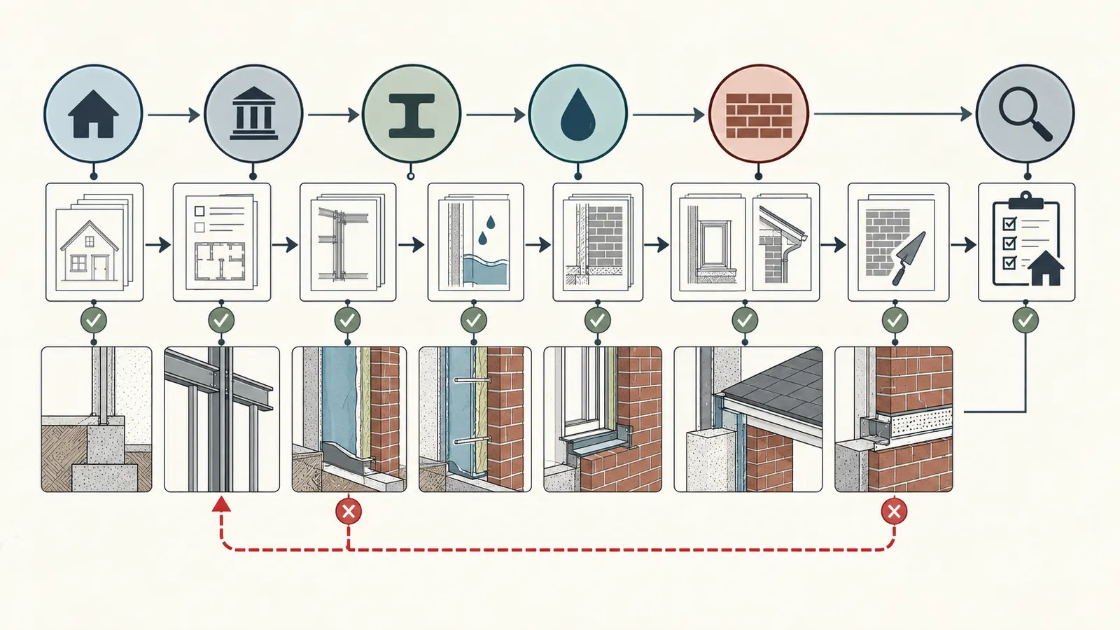
Release the wall section, jurisdiction and material inputs as one package #
Before construction, release one coordinated package that shows the actual brick veneer assembly and names the people who will act on it. A generic “brick exterior” note is not enough because support, cavity width, tie attachment, flashing, openings and roof intersections can change from elevation to elevation.
Start with the jurisdictional and design inputs
Create a cover sheet for the handoff. Put the following on it:
- Project address and the actual permit jurisdiction or AHJ.
- Permit number, adopted residential or building code edition, amendments and relevant inspection stages, if available from the permit file.
- Structural design documents and the current architectural wall sections, elevations and details.
- Framing type, sheathing type, exterior insulation location and any interior vapor-retarder strategy.
- Brick unit dimensions, nominal veneer thickness, mortar type/color, joint profile and accessory shapes.
- Foundation ledge, slab edge, shelf-angle, roof-member or lintel support locations, including stepped or suspended portions.
- WRB or air-barrier product, flashing products, tapes, primers, sealants, transition membranes and the manufacturer's installation manual.
- Tie or anchor type, corrosion-resistance specification, fastener and approved attachment substrate.
- Window, exterior door, roof, deck, chimney, porch, garage and mixed-cladding interfaces.
- Grade, finished-ground, paving and drainage assumptions at each base-of-wall condition.
- Exposure facts relevant to the design: wind-driven rain, severe exposure, snow, freeze-thaw, hot-humid conditions, coastal corrosion or wildfire requirements where the project designer identifies them.
- Materials lead times and the exact date at which the WRB's permitted exposure period, if any, begins.
Some of these are design inputs, not homeowner measurements. The value of the list is that it reveals a missing answer early. If the team cannot say where the brick is supported or how water at a roof-to-wall intersection exits, the question belongs in design coordination before the first course is laid.
Use a hierarchy when documents disagree
When a drawing, product manual, trade assumption and code summary disagree, do not select the easiest detail yourself. Record the conflict and route it through the hierarchy that applies to the project:
- The permit jurisdiction's adopted code and written direction control legal compliance for that jurisdiction.
- The stamped or otherwise responsible structural and architectural design controls the project-specific geometry, loading assumptions and interfaces within the professional's scope.
- The exact product installation manual controls that product's approved substrates, laps, primers, sealants, cure, exposure and compatibility limits.
- The masonry and roofing trades control their means and methods within the approved design and safety requirements.
- BIA, PNNL, DOE and IIBEC provide technical context and best-practice warnings, but they are not a substitute for the adopted code or project design.
For example, the 2024 International Residential Code Chapter 7 contains model-code provisions about veneer support, flashing and weep holes. That does not prove that the 2024 IRC is adopted at your address, nor does the chapter answer whether your particular shelf angle, window head or proprietary WRB detail is designed correctly. Put “model-code reference—confirm adoption” in the matrix whenever you use it.
The IIBEC technical advisory is especially useful as a reason to ask a better question. It explains that some residential brick veneer details have met cited code language while differing from long-accepted trade practice, and it calls out particular moisture concerns in humid or wet conditions. IIBEC also states that its advisory is general information, does not supersede a code or regulation, and is not a jurisdictional standard of care. Treat it as a design-review prompt, not as authority to reject a wall by yourself.
Freeze selections that change the wall geometry
Brick is not just a finish color. A change from standard to thin brick, from one brick thickness to another, from a running bond to a special pattern, or from flat units to corbels and arches can change support, coursing, flashing height and tie placement. A change in window trim can move the plane where water exits. A change in exterior insulation can consume cavity depth or require a different anchor.
Ask the builder to identify selections that are “appearance only” and those that alter the approved assembly. If a selection alters the dimension from the back of brick to the WRB, the position of the support, the height of a flashing line, the location of a tie or the material interface, it needs a design review. Do not rely on a verbal assurance that a skilled mason can make it work.
Build the material submittal record
The record should name the actual products, not only generic categories. “Flashing” could mean metal, flexible membrane, preformed pan or a proprietary through-wall system. “House wrap” could mean a sheet WRB, a fluid-applied barrier, a drainable wrap or a system with a separate air-barrier layer. Each has different joints and compatible accessories.
For the selected WRB, save the current product data and the complete installation guideline. As one example, DuPont's Tyvek Fluid Applied WB+ product sheet says that joint treatment and flashing occur before application, that application is spot-checked at a stated 25 mils, and that voids and pinholes are repaired. It also limits the product to its stated drainage-wall, exposure and professional-use conditions. Those values belong to that product sheet; they are not universal WRB rules.
Record:
| Material record | What to capture | Why it matters at handoff |
|---|---|---|
| WRB/air barrier | Product, system components, installation manual, substrate and permitted exposure | The wall may look complete while its drainage and air-control layer is not continuous. |
| Through-wall flashing | Product, thickness or type where specified, termination, laps, compatible sealant and end dams | Water must have a continuous path from cavity to exterior without relying on an unapproved adhesive. |
| Weep accessories | Open head joints, vents, mesh or collection device and the detail they serve | A weep that is missing, sealed or clogged cannot perform the same way as the drawn outlet. |
| Ties/anchors | Product, corrosion class, fastener, substrate, layout and engineer's schedule | The visible brick can conceal whether the anchor reaches structure. |
| Mortar and brick | Unit dimensions, mortar specification, color, lot/batch where retained and cleaning guidance | Repair or replacement later depends on knowing what was installed. |
| Sealants and primers | Product names, substrate compatibility and color | A generic substitute can be incompatible with the WRB, flashing or masonry. |
Verify support, ledges and openings before they disappear #
Do not allow brickwork to begin until the responsible designer or engineer and builder have resolved every support condition, including foundations, slabs, shelf angles, lintels, stepped ledges and upper-story transitions. The homeowner's task is to make the support evidence visible and to stop the handoff when the installed geometry does not match the controlled detail.
Trace the support line on every elevation
Mark each continuous and interrupted portion of veneer on the elevations. Then identify the actual support beneath it:
- Foundation or brick ledge at the base of the wall.
- Slab edge or thickened slab where the design uses it.
- Structural floor, shelf angle or other support at an upper-story setback.
- Lintel over a window, door, garage opening or other interruption.
- Roof-member, ledger or angle condition if the design suspends veneer over an opening or projects it at a roof.
- Stepped support where grade, walk-out basement geometry or a sloping foundation changes elevation.
The BIA checklist says brick veneer needs level support of adequate depth and identifies two-thirds of brick thickness as the model-code bearing summary. The ICC model text also describes support provisions and says flashing is located beneath the first masonry course above finished ground level and at other points of support. These are useful screening values, not permission to re-engineer a ledge in the field.
At a support hold point, request the builder's measurement record and an open-work photograph with a tape or scale. A photograph cannot prove capacity, anchorage or reinforcement. It can show that the wrong support is in the wrong place, that a ledge is visibly discontinuous, or that a planned flashing line has nowhere to go. Capacity, load path, attachment and deflection belong to the structural professional.
Worked dimensional example: test the bearing relationship, then stop at design
The following is an illustrative modeled example, not a design recommendation or a site measurement.
Assume the selected brick has a nominal thickness of 3 5/8 inches. A screening calculation based on the two-thirds model-code summary is:
minimum screening bearing = 3 5/8 in × 2/3
Convert the mixed fraction first:
3 5/8 in = 3.625 in
Then:
3.625 in × 0.6667 = 2.4168 in,
or approximately 2 7/16 inches of brick thickness in this illustrative relationship. This does not tell you the required ledge width, because the ledge must also account for the cavity, WRB/flashing geometry, tolerances, drip edge, support edge distance, reinforcement, eccentricity, construction loads and the design's chosen materials.
Now show sensitivity to brick thickness, keeping the same screening fraction only to demonstrate why a selection change matters:
| Illustrative brick thickness | Calculation at 2/3 | Screening result |
|---|---|---|
| 3 1/2 in (3.500) | 3.500 × 0.6667 | 2.333 in, about 2 1/3 in |
| 3 5/8 in (3.625) | 3.625 × 0.6667 | 2.417 in, about 2 7/16 in |
| 4 in (4.000) | 4.000 × 0.6667 | 2.667 in, about 2 2/3 in |
The sensitivity is 0.6667 inch of screening bearing for each 1-inch change in veneer thickness. A 1/2-inch change would move this illustrative result by about 0.333 inch. That is enough to trigger a coordination question even though it is not a capacity calculation. Ask: did the approved ledge, angle or lintel detail change with the brick selection? If not documented, hold the selection-to-design handoff.
This example also shows what not to infer. You may not infer that a measured ledge is structurally adequate because its width is larger than 2 7/16 inches. You may not infer that a level-looking support has adequate anchorage. You may not infer that mortar thickness can repair inadequate bearing. You may not infer that an angle is adequate because it is a common size. Record the actual dimension, then send the question to the structural designer or engineer.
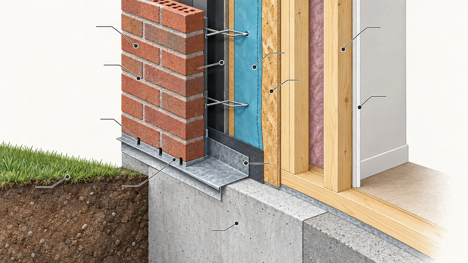
Check the base of wall and finished grade together
Base-of-wall readiness has two separate questions: does the veneer have designed support and flashing, and will the finished ground or paving leave the drainage outlets where the design expects them? Do not bury or cover a flashing line because the rough grade looks acceptable.
PNNL Building America says brick veneer base flashing should start behind the bottom edge of the WRB, extend across the support ledge and hang down, with weep holes in the bottom course to let water drain onto the flashing. Its guidance also explains that base, opening, roof-wall and penetration flashings must work as one drainage plane. Use the PNNL bottom-wall flashing guide to frame the review, then confirm the actual detail with the project designer and AHJ.
At the base hold point, request:
- A marked elevation showing finished grade, paving, patios, steps and planting zones.
- The designed height of the first course, flashing, drip edge and weeps above the relevant finished surface.
- Confirmation that backfills and utility trenches affecting the work are closed, compacted or otherwise released by the builder.
- Confirmation that foundation waterproofing or dampproofing called for by the design is in place before the veneer hides it.
- A photograph of the flashing leg, drip and WRB relationship before brick covers it.
- A repair action if grade will cover or pond against an outlet.
Do not turn a generic height recommendation from a national guide into a local rule. If the exact grade or clearance is governed by the adopted code, floodplain rule, accessibility design, or an AHJ detail, name and verify that jurisdiction-specific requirement in the project record. If you do not have the jurisdictional text, say so; do not fill the gap with a remembered number.
Check lintels and points of support, not just the foundation
Masonry openings create both a support change and a drainage interruption. The lintel must carry the brick above the opening, while flashing must capture water that reaches the cavity and direct it to weeps. A head flashing installed without a suitable support, or a lintel installed without a way for the water to exit, is an incomplete handoff.
For every window, door and garage opening, record the opening ID, rough-opening width, brick coursing, lintel or shelf-angle detail, flashing location, weep location, end dams and the responsible reviewer. The BIA advanced-flashing note describes added care at complex elements and gives tray, stepped and end-dam examples for bay windows and arches. It also explains that roof flashing alone does not address water that penetrates the brickwork at a bay; through-wall flashing is still part of the water-management detail. See BIA Advanced Flashing before accepting a “roof flashing will handle it” explanation.
Verify framing and tie substrates before masonry
The tie schedule is a design and installation item, not a visual decoration. The BIA checklist says the tie's backing attachment should reach a stud rather than only the sheathing, and it identifies spacing and area limits for the common checklist arrangement. If exterior insulation, steel framing, masonry backing or a proprietary anchor is present, those assumptions may not apply.
Ask for the tie schedule and an elevation layout showing where ties land relative to studs, openings, corners, control or expansion joints, and support breaks. Confirm that the actual fastener is the one in the detail. A nail that looks similar is not evidence of equivalent holding power. A tie installed into sheathing is not proof that it reaches the designed structural member. The BIA workmanship checklist is a prompt for this check; the responsible engineer or designer must resolve the actual anchor design.
Prove the drainage plane, cavity and flashing sequence before brick #
The drainage system must be continuous from each upper transition to each lower outlet before the masonry crew covers it. The reliable way to inspect continuity is to trace water's intended path downward: exterior brick, cavity, flashing, weep, exterior grade. Then trace the WRB and air-control layer behind it: top lap, side lap, opening transition, base flashing and penetration seal.
Use the bottom-up sequence
PNNL's drainage-plane guide says layers should overlap rather than underlap so bulk water drains down and out. Its sequence starts at the bottom, installs flashing first where needed, places the lower drainage-plane layer so it overlaps the flashing, and continues upward. It also warns against reverse shingling at roof-wall and other flashing intersections.
The exact product sequence must come from the selected system. As a homeowner, use this generic sequence to identify a missing interface, not to instruct a trade to violate a manual:
- Resolve support, substrate repairs, framing and penetrations.
- Install base, opening, roof-wall, deck, shelf-angle and other designed flashings at the correct layer.
- Install the WRB or air barrier so it laps over or integrates with the flashing in the designed shingle direction.
- Treat seams, corners, fasteners and penetrations using compatible system components.
- Confirm the brick cavity and drainage accessories preserve the path to the flashing and weeps.
- Start masonry only after the open-work hold point and any required inspection.
- Keep weeps open and continue to document support and tie installation as courses rise.
Reversing the order at one roof, window or deck detail can create a path behind the flashing. The issue is not whether the materials overlap somewhere; it is whether the upper layer directs water onto, rather than behind, the lower layer.
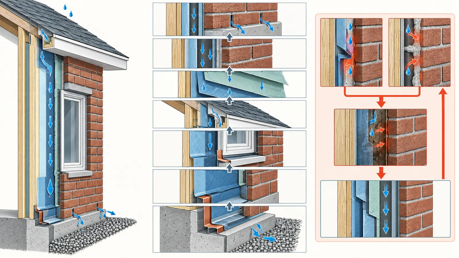
Treat the cavity as a dimensional and cleanliness condition
PNNL identifies a nominal 1-inch gap behind brick veneer in the guidance that references the 2009 IRC and warns that mortar bridging can channel water to the framed wall by capillary action. The BIA checklist likewise says the nominal 1-inch air space keeps brick and mortar from contacting the sheathing and should not be clogged enough to inhibit drainage.
The ICC explanation of the 2018 IRC change provides an important nuance: the code clarification acknowledges that some mortar spills occur during construction, while distinguishing limited spills from a cavity blocked enough to impair drainage. This is not a license to tolerate a visibly bridged or packed cavity. It is a reason to ask how the mason and builder will keep the drainage function open and how a dispute will be resolved.
Before work, establish how the team will address:
- Mortar droppings accumulating at the base.
- Mortar fins touching the WRB or sheathing.
- Insulation, mesh or collection media occupying the cavity.
- Ties bent, crowded or protruding into the drainage path.
- Flashing end dams, laps and outlets blocked by mortar.
- Weep vents sealed by sealant, foam, paint or mortar.
- Debris in the cavity from framing, roofing, electrical or HVAC work.
Do not insert a tool into the cavity, cut a tie, scrape the WRB or pressure-wash behind installed brick as a homeowner. Have the builder and mason show the safe inspection method. If the only proposed remedy is to drill random holes or “open” joints after the fact, stop and ask the designer or engineer whether the repair preserves the designed drainage and structural system.
Make the WRB and air barrier handoff observable
The WRB is not a magic sheet behind the brick. DOE's Building Enclosure Science drainage-plane guidance says the WRB should cover the house, its seams should be taped, and the drainage plane should lap over flashing at doors, windows, penetrations and wall tops or bases. PNNL similarly describes a sealed, continuous plane and compatible treatment at penetrations.
The owner record should show the following for each wall or elevation:
| WRB/air-barrier observation | What it can establish | What it cannot establish |
|---|---|---|
| Product name and installation manual saved | Which system rules the crew should follow | That the crew followed every rule |
| Seams and fasteners visible in photos | Whether obvious gaps, tears or unsealed penetrations exist at that moment | Future damage or hidden adhesion |
| Base flashing behind or integrated with WRB | Whether the intended lap is visible before concealment | Compatibility or long-term durability without professional review |
| Window/door pan, jamb and head transitions documented | Whether the designed sequence can be traced | Air leakage or water test performance |
| Roof-wall and deck intersections marked | Whether special conditions were considered | That a roofer's detail is compatible with the brick cavity |
| Product-specific thickness, cure or exposure record | Whether the applicator reported the manual's required check | That an owner has independently tested the product |
Do not confuse water-resistance with air-barrier continuity. A WRB may stop liquid water under its tested conditions and still require separate seam, joint and penetration treatment to serve as an air barrier. Conversely, a product marketed as an air barrier does not eliminate the need for a drainage path behind brick.
If the project uses a fluid-applied product, use the actual manual rather than a sheet-WRB checklist. DuPont's 2025 information sheet, for example, says the product is intended as part of a membrane drainage wall system, not a wall without a continuous drainage path; it gives product-specific application, cure and exposure limitations and identifies the product as for professional use. The DuPont product information sheet is evidence about that product only. Ask the applicator for the product-specific inspection record and the repair log for voids or pinholes.
Coordinate moisture control with climate and insulation
Climate affects the consequences of a weak drainage path and the design of vapor and thermal layers. DOE's Moisture Performance of High-R Wall Systems reports research across all climate zones involving bulk water, construction moisture, vapor and capillary transport. It recommends coordinating air sealing and drainage-plane details to avoid or minimize leaks and moisture accumulation, and it notes that high-R assemblies can use different layer permeances and drying paths.
IIBEC's advisory gives a more pointed warning for certain brick assemblies: in hot-humid conditions, solar and vapor drive can exacerbate moisture movement when saturated masonry and mortar contact moisture-sensitive layers. That discussion is not a universal diagnosis of every hot-humid wall. It is a prompt to have the responsible designer analyze the actual sheathing, insulation, vapor-retarder class, air-conditioning strategy and drainage cavity.
Ask the designer these questions in writing:
- What climate-zone and moisture-load assumptions were used for the wall assembly?
- Where can the wall dry if rain enters the brick or construction moisture remains?
- Does exterior insulation change the required cavity, tie length or flashing geometry?
- Does an interior vapor retarder or low-permeance exterior layer limit drying?
- Are there high-R, fiberboard, foil-faced, foam, masonry or mixed-cladding conditions that require a different detail?
- Does the selected WRB's vapor and liquid-water behavior match the assembly analysis and its warranty conditions?
The safest owner action is to capture the answers and the drawing reference. The owner should not select a vapor retarder, remove insulation or approve a mortar-filled cavity based on a general internet rule.
Check flashings and weeps as a system
The BIA checklist places weeps directly above flashing and gives approximately every third brick or 24 inches on center as one common guidance example. The ICC 2024 IRC text cited above gives a different model-code maximum for weepholes in the cited provision. This is exactly why the matrix records the source and scope rather than turning one number into a universal instruction. Ask which adopted code provision and project detail apply, then record the actual layout.
For each flashing line, mark:
- Where water enters the cavity above the line.
- The flashing's horizontal run and its exterior drip or termination.
- The vertical leg and its relationship to the WRB.
- End dams or turned-up ends where the detail requires them.
- The exact weeps or vents that discharge the line.
- How corners, steps and changes in support are lapped.
- What prevents mortar from blocking the outlet.
The visual question is not “Can I see shiny flashing?” It is “Can the team trace water from the cavity onto the flashing and through a clear outlet without crossing an unsealed reverse lap or a mortar bridge?” If the answer depends on a hidden membrane or a manufacturer's accessory, retain its installation detail and ask the responsible trade to identify it on the photo.
Coordinate windows, doors, roofs, corners and mixed cladding #
Every place where the brick plane changes, stops or meets another material is a separate readiness condition. Openings and roof intersections deserve their own rows in the matrix because a wall can have an apparently good base detail and still leak at a window head, bay roof, deck ledger, chimney or siding transition.
Windows and exterior doors
The window or door is installed in a rough opening that must connect to the wall's water and air layers before the brick covers the perimeter. PNNL's drainage-plane guidance describes pan, jamb and head flashing concepts and says the drainage plane should integrate with opening flashings. Use the project's window manufacturer instructions and approved wall detail for the actual sequence.
Create an opening schedule with one row per opening:
| Opening ID | Wall detail | Pan/sill evidence | Jamb evidence | Head flashing evidence | Brick/lintel and weep evidence | Reviewer |
|---|---|---|---|---|---|---|
| W-01 | Detail A-5 | Photo/date and product | Photo/date and lap direction | Photo/date and end condition | Open-work photo and elevation mark | Named builder/designer |
| D-01 | Detail A-6 | Threshold and sill transition | Door-frame transition | Head flashing and brick support | Weeps and sealant plan | Named builder/designer |
The table is intentionally a record template, not a universal installation recipe. Some windows use nail fins, some use clips or masonry openings, and some details rely on a sill pan or a field-applied transition. What matters is that the responsible professional can show the approved sequence and the owner can identify whether the visible work matches it.
Do not infer that a bead of sealant around the finished window substitutes for a pan, jamb, head or WRB transition. Do not infer that a window that is dry on the day of a walk-through has a functioning drainage path. Do not infer that brick touching a frame is acceptable without the project's movement and sealant detail. If the masonry opening is not coursed or aligned with the window detail, ask the mason and designer to resolve it before proceeding.
Roof-to-wall, porch and deck intersections
Where a roof, porch, deck or lower roof meets the brick wall, the assembly may need step flashing, counterflashing, through-wall flashing or a combination. The BIA advanced-flashing note says stepped or waterfall flashing is used where brick intersects a sloping surface and describes special care at bay windows, stepped foundations and arches. PNNL likewise identifies roof-wall intersections as common flashing locations and warns that reverse shingling can direct water behind a flashing layer.
For each intersection, ask for a section or enlarged detail that names the trades in sequence. A useful handoff is:
- Designer identifies the intended brick cavity, support and flashing line.
- Framer provides a sound substrate and opening for the detail.
- Roofer installs or leaves accessible the roof-side flashing components required by the detail.
- WRB installer integrates the wall drainage plane over or with the flashing as the product requires.
- Mason installs the brick, cavity accessories and weeps without closing the outlet.
- Builder photographs the open work and confirms the next trade did not damage it.
The order varies by assembly. The matrix is not a means-and-methods directive; it is a way to expose an unassigned dependency. If the roofer says the masonry contractor owns the flashing, and the mason says the roofer owns it, the wall is not ready for brick.
Bay windows, arches and stepped foundations
Complex geometry turns one flashing line into several pieces or a formed tray. BIA's advanced note describes tray flashing one or two courses above certain bay roofs, stepped flashing around triangular areas, gutter-flashing alternatives for some short openings, and end dams at arches. Use those examples to ask whether the project has a drawn solution; do not copy a dimension from the example into a different house.
At a bay or arch hold point, collect:
- An enlarged detail with section and elevation.
- The point where the top tray or stepped flashing meets the WRB.
- The direction of laps and any compatible sealant.
- The end dams and weep outlets.
- The brick course and support geometry below the transition.
- The roofing detail, where a roof intersects the masonry.
- The named person who accepts the open work.
At a stepped foundation, check that flashing and weeps remain at the designed, above-grade discharge line. BIA's note says flashing and weeps should be above grade in stepped conditions and describes a solution where the exposed foundation height changes to keep the water exit functional. The project designer and AHJ must resolve the actual grade, flood, foundation and appearance conditions.
Chimneys, fireplaces and mechanical penetrations
A masonry chimney, fireplace opening, dryer vent, hose bib, electrical box, conduit, refrigerant line or exterior light interrupts the WRB and may interrupt the brick cavity. The BIA checklist specifically asks whether mechanical work that would affect brickwork is in place and whether roof cuts for a masonry chimney are complete. Use that checklist question as a prestart prompt, then apply the actual mechanical, roofing, fire-separation and manufacturer requirements.
Make a penetration map. For each item, record its location, trade, sleeve or flashing detail, sealant or transition product, clearance requirement, and whether the brick course or accessory shape changes. The homeowner can photograph the open transition from a safe location. A qualified trade must install or modify it.
Do not let a late utility rough-in force a hole through installed flashing, a lintel, a tie, a chimney clearance or a completed wall. If the late work is unavoidable, the builder should issue a change record and have the responsible designer or engineer confirm the revised detail before drilling or cutting.
Brick-to-siding and other cladding transitions
A horizontal change from lap siding above brick creates a gap because the two claddings have different drainage planes and thicknesses. BIA's brick veneer builder note describes the need for durable flashing at a horizontal lap-siding/brick transition so water does not fall into the brick cavity or behind the adjacent siding. Use the actual transition detail for the selected siding and WRB.
Record:
- Which cladding is above and which is below.
- Where each cladding's drainage plane ends.
- How the upper layer laps over the transition flashing.
- Where the brick cavity drains and how the outlet remains clear.
- How corners, trim, sealants and movement are handled.
- Whether a horizontal band, shelf angle or change in support occurs.
At a vertical brick-to-siding joint, the exterior trim may shed water but it does not automatically prove that both behind-cladding drainage layers connect. Ask for the section, not just the elevation. Mixed cladding is a handoff between two systems; no single trade should be expected to infer the missing connection.
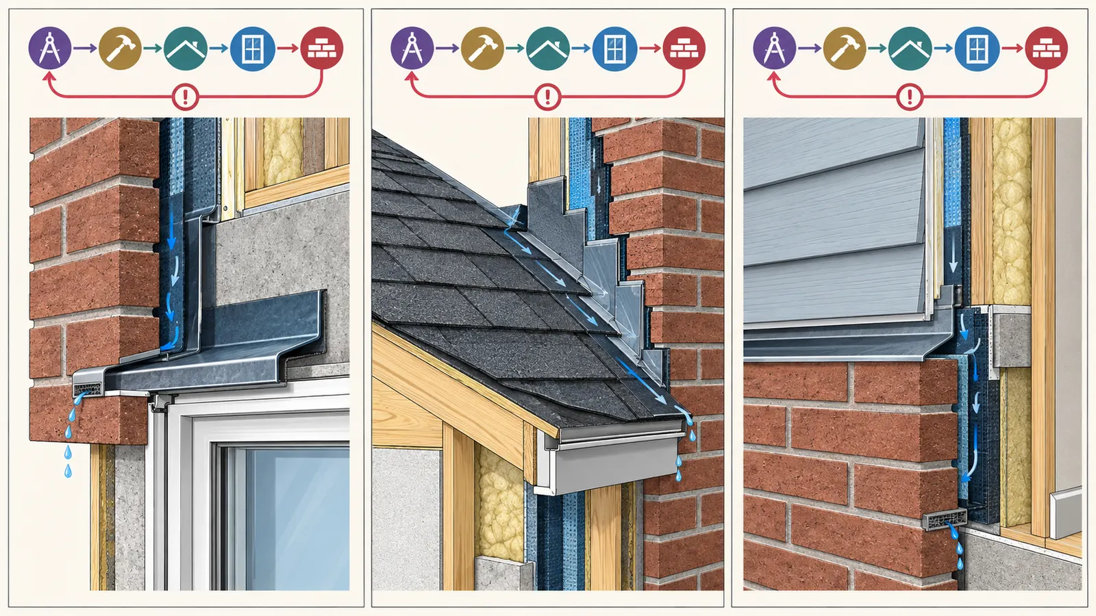
Run masonry hold points and keep a concealed-work record #
A useful masonry inspection plan has at least three hold points: before masonry, during representative open work, and after the accessible brickwork is complete. The point is not to turn the homeowner into a site inspector. It is to prevent an irreversible concealment event from being accepted without the responsible people and evidence.
Hold point 1: prestart release
Schedule this meeting before brick, mortar, ties, flashing accessories and scaffolding are committed to an elevation. The builder should lead, with the mason and relevant designer or engineer available. The owner can use this agenda:
- Confirm project address, permit jurisdiction, permit set and current drawing revision.
- Walk every elevation and identify support type and flashing lines.
- Confirm framing and sheathing are complete, dry enough for the designed materials and repaired where required.
- Confirm foundation waterproofing, backfills, trenches, grade assumptions and access.
- Confirm WRB/air-barrier product, flashing components, tapes, primers and sealants.
- Confirm the bottom-up drainage-plane sequence and each opening/roof/mixed-cladding detail.
- Confirm cavity dimension and how mortar droppings will be controlled.
- Confirm tie/anchor product, substrate, fastener and layout.
- Confirm brick, mortar, accessory shapes and cleaning method.
- Confirm windows, doors, roof cuts, hearths, mechanical penetrations and chimney work that affect brick.
- Confirm required permit inspections and the builder's internal hold points.
- Confirm weather, storage and product exposure limits that apply to the actual materials.
- Confirm who can release a repair and who can authorize a design change.
The BIA checklist includes similar preparation questions—access, framing, backfills/trenches, foundation waterproofing, brick ledge, WRB, mechanical work, hearth/chimney work and materials. It also tells the user to address a nonconforming item before further construction progresses. Use the BIA checklist as a source-linked agenda, not as a replacement for the project's approved details.
Hold point 2: representative open work
Do not wait until the last brick is laid to see whether the sequence works. Select a representative wall bay that includes a base, a typical opening, a corner, a tie line and—if present—a transition. If the house has unusually complex conditions, select more than one bay.
At this hold point, ask the responsible trades to demonstrate or document:
| Item | Observable evidence | Stop/repair trigger |
|---|---|---|
| Support | Ledge, angle or lintel matches the released detail and is ready for the brick geometry | Location, width, level, attachment or bearing differs from the detail |
| Cavity | A planned drainage gap exists and is not bridged by fins, debris, insulation or mortar | Cavity is blocked, narrowed below the designed condition or cannot be inspected safely |
| Base flashing | Flashing leads from behind/integration with WRB across support and out to discharge | Reverse lap, missing drip, damaged membrane, no outlet or incompatible sealant |
| WRB/air barrier | Seams, corners, penetrations and opening transitions are treated per product manual | Torn, unsealed, exposed beyond product limit or unclear transition |
| Ties | Correct anchors reach the designed substrate and align with the schedule | Wrong fastener, unsupported attachment, missing tie or tie occupying the drainage path |
| Opening | Sill, jamb, head, lintel, flashing and weep detail can be traced | The only evidence is exterior sealant or a generic verbal approval |
| Weeps | Outlets are at the designated flashing lines and remain open | Mortar, sealant, mesh or debris blocks the outlet |
| Mixed transition | Upper and lower drainage paths are connected and protected | A gap, ledge or flashing line ends without a named discharge |
These triggers are decision prompts, not legal defect findings. The next action is to hold the affected area, photograph the condition, identify the responsible party, and ask for repair or written design resolution.
Hold point 3: representative workmanship and completion
As brick rises, confirm the workmanship that protects the drainage and appearance. The BIA checklist says full mortar joints help resist wind-driven rain, that “clipping” a head joint does not fill it adequately, and that tooling a joint at thumbprint hardness compresses the face and can seal hairline cracks. It also recommends careful cleaning rather than raw muriatic acid and low-to-medium water pressure in the described cleaning process.
The homeowner need not judge mortar chemistry or joint strength by eye. Instead, record the mason's agreed workmanship standard and ask the builder or responsible inspector to verify it. Look for visible conditions that warrant a professional response:
- Head joints appear only partially filled across a repeated area.
- Joints are left untooled where the approved appearance and workmanship standard calls for tooling.
- Mortar smears or cleaning residue are being treated with an unapproved chemical.
- Brick units are cracked, chipped, displaced or visibly out of plane.
- Expansion or movement joints shown on the plans are omitted or filled with mortar.
- Cavity outlets are blocked as courses close.
- A tie or flashing accessory is visibly displaced from the detail.
Do not use a hose, pressure washer, acid or screwdriver as an owner test. Cleaning chemicals and masonry dust can injure people and damage the wall. The mason should follow the brick, mortar, cleaning-product and safety instructions; the builder should protect adjacent materials and landscaping.
Photograph evidence so it can be interpreted later
A good photo log answers “where, when, what and whose decision.” For each photo, record:
- Project address and elevation.
- Date and approximate time.
- Drawing/detail reference.
- Opening, support or transition ID.
- A wide photo locating the condition and a close photo showing the interface.
- A scale or known reference when safe and permitted.
- Product name if the photo shows a membrane, flashing or accessory.
- Open, repaired or concealed status.
- Responsible trade and reviewer.
- Follow-up date and resolution record.
Photographs are records, not tests. A photo can show a lap direction or visible weep. It cannot prove a hidden sealant bead, attachment capacity, water resistance under wind pressure, air leakage, mold risk or long-term durability. Do not crop out the wall context or silently relabel a photo after a dispute. Preserve the original and add an explanatory caption.
Use the Brick Veneer Readiness and Handoff Matrix #
The matrix is ready to use when each row has a named project input, a responsible party, a sequence, observable evidence, a hold point, a failure action and a next handoff. It is designed to be copied into the project's coordination log, not treated as an official inspection form.
Method, inputs and limitations
The method is source-derived synthesis. First, identify the wall assembly and its jurisdictional context. Second, split the work into the irreversible handoffs: design release, support, drainage plane, cavity, openings, transitions, ties, masonry and closeout. Third, assign each row to the person who can decide or perform the work. Fourth, define evidence that a homeowner can request without performing hazardous work. Fifth, attach a hold point and failure branch.
The matrix's inputs are the project address and AHJ; approved wall section and revision; brick thickness and pattern; foundation, slab, shelf-angle and lintel geometry; framing and sheathing; WRB, air barrier and flashing products; tie type and substrate; openings; roof and cladding transitions; finished grade; climate and exposure assumptions; and the required inspection sequence.
Limitations are essential. The matrix cannot approve structural design, calculate wind or seismic loads, determine fire or flood compliance, test water or air leakage, decide whether a product warranty applies, or replace the designer, engineer, builder, mason, manufacturer or permit-jurisdiction building official. It also cannot resolve an unknown local rule. Where a row has no responsible professional or no controlled detail, the row is incomplete.
The matrix
| ID and decision | Inputs to attach | Responsible party | Sequence | Observable evidence | Hold point | Failure action and next handoff |
|---|---|---|---|---|---|---|
| R1. Is the assembly defined? | Address/AHJ, permit set, wall section, brick type, framing, sheathing, insulation and WRB | Designer/architect and builder | Select and coordinate the assembly before procurement | Dated wall section names support, cavity, WRB, flashing, ties, weeps and transitions | Design release | Stop selection or procurement; designer resolves the missing interface; builder redistributes revision |
| R2. Is local authority clear? | Permit number, adopted code edition/amendments and inspection stages | Builder/permit applicant | Confirm before field assumptions | Written AHJ identity and permit record | Jurisdiction release | Ask the actual permit jurisdiction; do not use model-code text as local approval |
| R3. Is support continuous? | Brick thickness, ledge/slab/angle/lintel details, elevations, grade and upper-story supports | Structural designer/engineer and builder | Verify framing and supports before flashing/masonry | Measurement/photo and design reference for each support break | Support hold | Hold affected elevation; engineer/designer resolves capacity, bearing, attachment or geometry |
| R4. Is the base drainable? | Base flashing, WRB, ledge, weeps, grade/paving and waterproofing | Builder, envelope trade and mason | Install support-side flashing and integrate WRB before first course | Open-work photo traces leg, drip and outlet | Base hold | Repair before brick or grade; designer/AHJ decides any clearance conflict |
| R5. Are openings ready? | Window/door schedule, pan/jamb/head details, lintels, flashing and brick course | Window installer, builder, designer and mason | Finish approved opening transitions before veneer | One record per opening with photos and detail ID | Opening hold | Stop opening; responsible designer/trade repairs or issues controlled revision |
| R6. Are roof and cladding transitions ready? | Roof slopes, step/counterflashing, bay/arch/porch/deck and siding details | Designer, roofer, builder and mason | Sequence roof/WRB/masonry components per detail | Enlarged detail, lap direction, end dam and outlet photo | Transition hold | Hold both trades; designer coordinates, builder records change |
| R7. Is cavity width and path protected? | Nominal cavity, insulation, ties, mortar-control accessory and collection device | Designer/engineer, mason and builder | Set ties and masonry without bridging the drainage path | Representative open cavity and outlet evidence | Cavity hold | Stop; remove/repair blocking as directed; engineer/designer evaluates damaged layers |
| R8. Are ties anchored as designed? | Tie product, corrosion class, fastener, stud/backing layout and spacing schedule | Structural designer/engineer and mason/builder | Mark substrate and install ties as courses rise | Product and open-work photos tied to elevation | Tie hold | Do not accept substitute fastener or sheathing-only attachment; engineer resolves |
| R9. Is the WRB/air barrier continuous? | Product manual, seam/tape/sealant list, flashing compatibility, exposure and cure limits | Envelope designer, WRB applicator and builder | Treat joints, flashing and penetrations before concealment | Product record, inspection/repair log and photos | WRB hold | Stop cover-up; applicator repairs; manufacturer/designer resolves compatibility |
| R10. Are weeps functional? | Flashing line, code/detail spacing, vent type, mortar-control accessory | Mason and builder; inspector as required | Place weeps directly at designed drainage lines while laying | Open, clear outlets visible at required locations | Weep hold | Clear or rebuild as directed; do not drill random outlets without design approval |
| R11. Is workmanship released? | Mortar specification, joint profile, brick pattern, cleaning product and movement joints | Mason, builder and designer | Lay, tool, clean and protect according to documents | Representative elevation, repair log and closeout photos | Workmanship hold | Correct repeated or isolated defects before acceptance; document decision |
| R12. Is the wall maintainable? | Final product list, photos, warranties, repair record, weep locations and inspection records | Builder and owner | Close out after repairs and required inspections | Handover packet and maintenance notes | Closeout | Builder completes missing record; owner escalates unresolved defect under contract/warranty |
How to fill one row without pretending to be an inspector
Take R4, the base drainage row. The input is not merely “flashing installed.” Attach the base detail, support geometry, WRB product, flashing product, grade plan and weep detail. The responsible technical action belongs to the builder and envelope/masonry trades, with design or AHJ review if the condition differs. The sequence is support and flashing, WRB integration, cavity protection, brick and weep. Observable evidence is a dated open-work photo that shows the path. The hold point occurs before the first course closes it. A failure action is to hold the area and route the mismatch to the designer or builder; the next handoff is only after repair or written resolution.
Now take R8, ties. The owner can retain the tie schedule and a photo of an open attachment. The owner cannot infer capacity from a photo or substitute a different nail. If the tie misses the structural member, the next handoff is to the engineer or designer, not directly to the mason for an improvised relocation. This distinction is the practical value of recording responsibility.
A compact scoring rule for project conversations
You may use a simple status count for coordination, not for code approval. Mark each row:
Gwhen evidence is attached, the responsible party is named and no unresolved exception is open.Ywhen evidence is partial but a named person and due date exist before concealment.Rwhen the work differs from the detail, the evidence is missing at a hold point, or no qualified person owns the decision.
Do not add the colors into a “readiness percentage.” One red support or drainage row can control the whole release even if eleven other rows are green. A score hides dependencies; the matrix exposes them. A project with ten green rows and one red lintel can still be unsafe to cover.
When a check fails, stop, repair or escalate before the next handoff #
The correct response to an incomplete brick-veneer condition depends on whether the issue is a missing record, a repairable installation defect, a design change or a possible concealed failure. The homeowner's safest branch is to preserve evidence, keep the affected area from advancing, and send the question to the professional who can decide it.
Failure and response matrix
| Observed condition | What you may conclude | What you must not conclude | Safest next action | Information to send |
|---|---|---|---|---|
| No current wall section at the site | Document control is incomplete | That the last drawing still applies | Hold procurement or the affected start and ask builder for the controlled revision | Address, sheet/revision, selections and affected elevations |
| Ledge or lintel dimension differs from detail | A coordination mismatch exists | That mortar or extra brick will make it adequate | Hold masonry and ask designer/engineer to resolve | Measurement, location, brick thickness, photos and drawing |
| WRB is torn or penetration is unsealed | Visible continuity is not complete | That brick will protect it | Builder holds cover-up; qualified applicator repairs per manual | Product, location, photo, exposure time and adjacent flashing |
| Flashing is reversed or ends without an outlet | The intended drainage path is not demonstrated | That exterior sealant will redirect concealed water | Hold; designer/trade issues repair detail | Section, lap direction, outlet, product and elevation |
| Cavity has heavy mortar bridging | Drainage may be impeded | That “some mortar spills” means any amount is acceptable | Stop and have builder/mason/designer determine safe correction | Representative photos, cavity dimensions, affected length |
| Tie misses stud or uses an unlisted fastener | Installed anchorage differs from the record | That a nearby tie or sheathing is equivalent | Hold and refer to structural designer/engineer | Tie product, fastener, location, backing and schedule |
| Weep is blocked | Outlet is not visibly functional | That drilling later is harmless | Mason/builder repair or designer-approved alternative before acceptance | Flashing line, outlet spacing/detail and photos |
| Window head has only finish sealant | Surface seal exists | That pan, jamb and head drainage are complete | Open the question with builder/window installer/designer | Opening ID, product, photos and approved window detail |
| Roof trade and mason disagree on flashing ownership | Handoff is unassigned | That one trade's usual practice covers the gap | Builder assigns the detail and sequence before work | Roof slope, wall section, trade scopes and photos |
| Product is outside exposure/cure limit | Manufacturer condition may not be met | That the warranty still applies | Stop cover-up and consult applicator/manufacturer/designer | Product, install date, weather, exposure and manual |
| Grade will bury a weep or flashing outlet | Finished conditions conflict with drainage | That landscaping can conceal it safely | Builder/designer/AHJ resolves grade and drainage before closeout | Site plan, finished grade, elevations and jurisdiction |
| Completed wall shows cracks, displaced units or staining | A visible condition merits professional review | The cause is known from appearance alone | Photograph, protect area and ask builder/designer/mason to inspect | Location, age, weather, pattern, adjacent openings and records |
The matrix uses “hold” as a project-control word, not a declaration of legal noncompliance. A hold means the next irreversible step waits for the named decision. The owner should send a calm written note: “At R6, the roof-to-wall detail on elevation East is not yet matched to the installed flashing visible in photos 2026-09-07-12 through -15. Please identify the responsible designer/trade, the repair or approved detail, and the release date before brick continues.” That creates a traceable handoff without directing a trade to perform an unsafe fix.
Separate repair from redesign
Some issues are workmanship corrections: a missing weep vent before the course is closed, an unsealed seam that the product manual allows the applicator to repair, a mortar smear that can be cleaned by the mason using the specified method, or a displaced accessory that can be reset without changing the design.
Other issues are redesign or engineering questions: inadequate bearing, a shelf angle with uncertain anchorage, changed brick thickness, a tie that cannot reach its specified substrate, a new roof intersection, insulation that consumes the cavity, a changed window size, or a flashing line that conflicts with finished grade. Do not accept a field fix merely because it is visually hidden or common in another project.
The distinction matters because a repair should restore the released design, while redesign changes the assumptions and may require a revised drawing, structural calculation, product approval, permit-jurisdiction review or warranty confirmation. The next handoff for a design question is to the responsible designer or engineer; the next handoff for a product compatibility question is to the manufacturer and envelope professional; the next handoff for a permit question is to the actual AHJ.
What the owner should keep after acceptance
At handover, request a compact wall record:
- Final approved wall sections and any issued revisions.
- The actual permit jurisdiction, permit/inspection records and any written official direction.
- Brick, mortar, flashing, WRB, sealant, tie and accessory product records.
- Base, opening, roof-wall, bay, arch, chimney, deck and mixed-cladding photos before concealment.
- Tie and support records supplied by the builder or engineer.
- WRB applicator inspection and repair records where a product system requires them.
- Masonry punch list, cleaning method and repair log.
- Locations of weeps, movement joints, concealed flashing lines and special transitions.
- Warranty documents and the exact conditions attached to products or workmanship.
- A maintenance note telling the future owner where to look for blocked weeps, sealant aging, cracks, staining, vegetation and grade changes.
Brick veneer is durable, but durability is not a reason to discard records. The BIA technical-resources index identifies maintenance guidance for weeps, sealant joints, mortar joints, brick and wall ties. A future repair professional needs to know what is behind the face, where the drainage lines discharge and which materials were installed. Store the record with the rest of the home's closeout documents and make it available to the next owner.
Hazard boundaries for a homeowner walkthrough
This is a moderate-safety construction decision. Brick work involves lifted materials, unstable partial walls, scaffolds, falls, mortar and cleaning chemicals, sharp flashing, power tools, roof edges and traffic around active construction. Do not enter an active masonry or roofing area without the builder's permission and required site protection. Do not climb scaffolding or roofs to inspect a detail. Do not handle fluid-applied WRB, solvent cleaners, acids, mortar dust or spray equipment. DuPont's product sheet, for example, identifies professional-use restrictions, respiratory and skin/eye precautions, and ventilation requirements for its fluid-applied product.
Structural work—cutting a lintel, altering a shelf angle, changing a ledge, drilling an attachment, removing brick or modifying a tie—belongs to qualified professionals. Excavation, grading near foundations, roof work, electrical or mechanical relocation, and any work that could affect a fire separation also belongs to the responsible trade and design professional. A remote photo review cannot verify hidden capacity, a water test, air leakage, moisture content, mold, code compliance or warranty eligibility.
Remote photos or video also cannot diagnose electrical safety, electrical clearances, or continuity at wall penetrations. A picture may show that a conduit, cable, light box, hose bib or other service crosses the wall, but it cannot establish whether the electrical installation is de-energized, properly supported, protected, bonded, clear of masonry and flashing, or continuous through the penetration. The homeowner must not enter or inspect the brick cavity or any confined space, and must not probe a penetration, move a cable, remove a cover, or expose concealed work. Before proceeding, route electrical questions to the responsible builder and electrical trade, wall and penetration questions to the designer or engineer, and adopted-code or inspection questions to the permit jurisdiction's building official.
If there is a fall, chemical exposure, unstable wall, suspected structural movement or active water intrusion, leave the area and contact the builder's safety contact or emergency services as appropriate. The matrix is for coordination; it is not an emergency procedure.
The next decision after the wall is accepted
After every row is green or has a documented, professionally accepted exception, the next decision is not simply “finish the brick.” It is whether the wall record is complete enough to support future ownership. Walk the elevations from bottom to top, compare the final surface to the opening and transition schedule, confirm weeps are not blocked, record visible cracks or displaced units, and ask for the repair status of every earlier yellow or red row.
Then decide one of three ways:
- Release to closeout: the required inspections and professional reviews are complete, the repair log is closed, and the owner receives the wall record.
- Release with a tracked item: the wall is not being concealed further, but a named professional has accepted a bounded outstanding item with a due date and documented effect.
- Do not accept: a support, drainage, product, tie, transition or safety question remains unresolved, so the builder must repair, redesign or escalate before final acceptance.
The page's practical purpose is to make that choice visible before brick veneer turns a drainage and support system into a hidden condition. For broader homeowner planning across design, materials and construction, continue through the Brictale blog, while keeping this wall-specific matrix with the home's permanent records.
Cite this guide
Brictale. “How to Prepare for Brick Veneer Installation on a New House.” Published 2026-09-13; updated 2026-09-13.
https://brictale.com/build/materials/prepare-for-brick-veneer-installation-new-house · Read the Markdown version
Original contribution: Brick Veneer Readiness and Handoff Matrix. A homeowner-facing readiness record that connects the approved wall section to support, drainage, openings, transitions, inspection hold points, failure actions and the next responsible handoff.
Sources and scope
Evidence behind this page
- The Brick Industry Association describes brick veneer as a drainage-type wall in which water may penetrate the brickwork, so an air space, flashing and weeps are needed to redirect water to the exterior.
Builder Notes 2: Basics of Brick Veneer Construction & Workmanship Checklist
Brick veneer drainage-wall principles and checklist guidance from the Brick Industry Association; not a project-specific approval or local code determination.
Accessed · Link to this claim - The Brick Industry Association checklist states that brick veneer needs level support of adequate depth, that the mortar joint on a brick ledge or slab should not exceed 3/4 inch, and that model codes require two-thirds of brick thickness to bear on foundation or lintel support.
Builder Notes 2: Basics of Brick Veneer Construction & Workmanship Checklist
BIA checklist and model-code summary for typical brick veneer support; actual support design, dimensions and adopted code remain project- and jurisdiction-specific.
Accessed · Link to this claim - The Brick Industry Association describes through-wall flashing as extending from the veneer face through the cavity to the backing and integrating behind or over the water-resistant barrier; it places weeps directly above flashing and gives approximately 24 inches on center as a checklist spacing example.
Builder Notes 2: Basics of Brick Veneer Construction & Workmanship Checklist
BIA technical guidance for common flashing and weep arrangements; exact location, material, laps, sealants and spacing must follow the approved detail, adopted code and product instructions.
Accessed · Link to this claim - The Brick Industry Association checklist says wall ties should be attached to structural framing rather than only sheathing, embedded in a mortar joint, and installed within its stated area and spacing limits; it also identifies full mortar joints, tooling and careful clean-down as workmanship controls.
Builder Notes 2: Basics of Brick Veneer Construction & Workmanship Checklist
BIA checklist guidance for common anchored brick veneer; tie design, fastener type, corrosion resistance and spacing are not universal substitutions for the structural detail or code.
Accessed · Link to this claim - The Brick Industry Association explains that sloping intersections, stepped foundations, bay windows and arches can require stepped or tray through-wall flashing, end dams and weeps, and that roof flashing alone does not replace through-wall flashing where water can enter the brickwork.
Builder Notes 3: Brick Veneer Construction—Advanced Flashing
BIA examples for complex brick veneer flashing geometry; the project designer and roofing/masonry trades must resolve the actual transition.
Accessed · Link to this claim - PNNL Building America says a continuous drainage plane should be integrated with flashing, with layers overlapped in shingle fashion so water drains down and out; it identifies the base, openings, roof-wall intersections and penetrations as connected details.
Flashing at Bottom of Exterior Walls
Building America Solution Center guidance for residential exterior-wall water management; it is general technical guidance and not a permit-jurisdiction inspection decision.
Accessed · Link to this claim - PNNL Building America identifies a nominal 1-inch gap behind brick veneer as model-code guidance and warns that mortar bridging can carry water to the framed wall; it also describes the gap as supporting drainage and drying.
Drainage Plane Behind Exterior Wall Cladding
PNNL guidance referencing the 2009 IRC and building-science principles; the adopted code, wall assembly, insulation placement and approved detail govern the actual project.
Accessed · Link to this claim - IIBEC cautions that a brick veneer detail can meet a cited code provision yet differ from long-accepted trade practice, and highlights moisture risk from mortar-filled cavities in humid or wet conditions; its advisory does not supersede a code or establish a jurisdictional standard of care.
Professional technical advisory updated in 2021; commentary on code-compliant residential brick veneer and regional moisture context, not a local rule or project approval.
Accessed · Link to this claim - The U.S. Department of Energy reports that high-R wall research examined bulk water, construction moisture, vapor and capillary transport across all climate zones, and recommends coordinated air-sealing and drainage-plane details to reduce leaks and moisture accumulation.
Moisture Performance of High-R Wall Systems
DOE Building Technologies research summary for new-construction high-R walls in all climate zones; it does not prescribe this home's insulation or vapor-control design.
Accessed · Link to this claim - The International Code Council's 2024 IRC chapter states that veneer support provisions address two-thirds bearing on support, that flashing is located beneath the first masonry course above finished ground level and at other points of support, and that weep holes have a maximum 33-inch on-center spacing in the cited provision.
2024 International Residential Code, Chapter 7 Wall Covering
2024 IRC model-code text as published by ICC; it is not automatically the adopted code in every U.S. state, county, city or other permit jurisdiction.
Accessed · Link to this claim - The International Code Council explains that the 2018 IRC clarification allows some mortar spills in the required drainage airspace while distinguishing limited spills from a cavity blocked enough to impair drainage.
Significant Changes to the 2018 International Residential Code
ICC explanation of a 2018 IRC change; it does not authorize a contractor to leave a blocked cavity or resolve a project-specific inspection dispute.
Accessed · Link to this claim - DuPont's 2025 Tyvek Fluid Applied WB+ product information says joint treatment and flashing are completed before application, the product is spot-checked at 25 mils with repairs for voids and pinholes, and its continuous-drainage path, exposure, cure and professional-use limitations must be followed.
DuPont Tyvek Fluid Applied WB+ Product Information Sheet
One selected manufacturer product and its 2025 information sheet; do not generalize these values to another WRB, flashing product, substrate, climate or warranty.
Accessed · Link to this claim - The U.S. Department of Energy Building Enclosure Science resource says the WRB should cover the house, seams should be taped, and the drainage plane should lap over flashing at doors, windows, penetrations and wall tops or bases.
Building Enclosure Science Intro: Drainage Plane Behind Exterior Wall Cladding
DOE educational guidance on a continuous drainage plane; exact materials and installation details remain subject to the approved assembly and manufacturer instructions.
Accessed · Link to this claim - The Brick Industry Association's brick veneer builder note identifies horizontal lap-siding/brick transitions as conditions requiring durable flashing to cover the gap created by the brick cavity and redirect water.
Builder Notes 1: Brick Veneer Construction
BIA transition guidance for a brick veneer and lap-siding interface; the project's approved mixed-cladding detail and product instructions control.
Accessed · Link to this claim - The Brick Industry Association technical-resources index identifies maintenance guidance covering sealant joints, mortar joints, weeps, brick, wall ties and related brick-masonry repairs.
Technical Notes—Technical Resources
BIA technical-resource index used to justify retaining a maintainable wall record; it is not a project inspection or warranty determination.
Accessed · Link to this claim