How to Plan a New-Home Automatic Water Shutoff and Leak-Detection System Before Rough-In
Choose and document a new-home leak-detection architecture before plumbing rough-in, including branches, access, power, controls, recovery and trade handoffs.
The short answer
Choose the architecture from the water branches it must cover, not from a device feature list. Before rough-in, map the service line, meter, PRV, irrigation, fire-sprinkler and automatic-appliance branches; classify each as monitored, excluded or separately sensed; then reserve model-specific pipe space, access, power, connectivity and manual recovery. Have the plumber, electrician, builder and fire-sprinkler designer verify their rows for the actual project jurisdiction.How to Plan a New-Home Automatic Water Shutoff and Leak-Detection System Before Rough-In
Choose the architecture from the water branches it must cover, not from a device feature list. Before rough-in, map the service line, meter, PRV, irrigation, fire-sprinkler and automatic-appliance branches; classify each as monitored, excluded or separately sensed; then reserve model-specific pipe space, access, power, connectivity and manual recovery. Have the plumber, electrician, builder and fire-sprinkler designer verify their rows for the actual project jurisdiction.
This guide is for a United States homeowner planning a new home before plumbing rough-in. It is a planning and coordination method, not a code approval, hydraulic design, fire-protection design, electrical design, installation instruction or emergency leak-diagnosis service. The actual authority having jurisdiction (AHJ)—the city, county, state, tribal or other permitting authority responsible for the project address—must answer local permit and adopted-rule questions. A qualified plumber, electrician, builder, designer and, where the home has fire sprinklers, fire-sprinkler designer must resolve the site-specific work assigned to each trade.
Remote guidance cannot assess or authorize entry into a crawl space, pit, tank, vault or another confined or potentially hazardous space. A crawl-space location on a plan is not permission for the homeowner to enter it. Do not enter such a space to inspect a sensor, valve or leak; ask the builder or an appropriately qualified local professional to inspect it, and use the appropriate local emergency service if there is an immediate danger.
The decision is not “Which smart valve has the most features?” It is: “Which leak-control architecture gives this home the intended coverage and response without creating an unsafe shutoff, an inaccessible service point, an unpowered controller, a network dependency nobody owns, or a branch that the homeowner mistakenly believes is protected?” EPA WaterSense separates moisture sensing from flow monitoring and notes that systems can combine technologies, focus on a point of use or monitor the point of entry, and either alert or activate a shutoff. Read the EPA WaterSense technical fact sheet as a category and planning source, then read the exact current instructions for the model actually specified.
The useful output before rough-in is a one-page branch map plus a release record. It identifies every water path, the proposed response, the responsible trade, the reserved physical provisions, the commissioning tests, the model revision and the next decision. A product can be changed later; a buried branch, crowded utility room, missing outlet or incorrectly coordinated fire-sprinkler connection is much harder to change after walls close.
Choose the architecture from coverage and intervention #
Choose point sensors when the priority is detecting water at known high-risk locations, choose whole-home flow monitoring when the priority is recognizing abnormal use across a water network, choose an automatic shutoff when the response must include closing a valve, and choose a combined system when both broad inference and local confirmation matter. The correct choice depends on which branches are included and which must remain continuously available—not on the label “smart.”
Know what each architecture can and cannot see
There are four useful architecture patterns for a new home. They are not four brands, and they are not mutually exclusive.
| Architecture | What it observes | What it can do | What it can miss | Pre-rough-in consequence | Best fit when |
|---|---|---|---|---|---|
| Point sensors only | Water at a sensor, cable or designated appliance area | Alarm locally and, for some products, notify a hub or controller | A leak outside the sensing footprint; a concealed pipe leak before water reaches a sensor | Reserve sensor locations, dry mounting surfaces, cable routes, battery access and a way to identify each zone | You want targeted protection, have known appliance risks, or cannot place a main-line device yet |
| Whole-home flow monitoring | Flow, pressure or usage behavior at the supply line or point of entry | Detect unusual flow or pressure patterns and send an alert; some systems also close a valve | A small or unusual leak may be ambiguous; it may not identify the exact room; excluded branches remain outside the measurement | Reserve straight or sufficient pipe length, service access, correct size, power, network path and a record of included branches | You want one broad view of domestic use and accept a pattern-based response |
| Automatic shutoff with local or remote control | A control signal or detected event that commands a valve | Close the selected water path, sometimes by app, panel or sensor | A valve cannot protect a branch installed upstream or around it; closing water can create a new operational problem if the event is not understood | Decide valve topology, manual bypass or override, access, power, position, bracing and recovery procedure | Limiting continuing flow is more important than identifying the exact leak first |
| Combined flow monitor, shutoff and point sensors | Whole-home flow behavior plus local moisture or cable events | Alert, infer, confirm at selected areas and close a defined valve | No combination guarantees every leak is detected or that a valve covers every branch | Coordinate the main device, each sensor zone, network/control path, power, branch exclusions and turnover training | The home has several high-consequence zones, automatic water users or remote-occupancy needs |
The EPA WaterSense description supports the basic distinction: moisture devices detect water where it appears, while flow devices measure flow or pressure and interpret irregular use; devices with shutoff capability can activate a valve, while others only alarm or notify. That means “whole-home” is a coverage claim about a monitored water path, not proof that the system knows the room or appliance where water escaped. A Moen Flo support page, for example, says the device alerts to abnormal usage but cannot determine exactly where a leak is in the house. A homeowner who wants room-level information may need point sensors even after choosing a whole-home device.
Separate detection from intervention
Detection asks, “How will the system recognize a possible loss?” Intervention asks, “What will happen next?” The choices may be independent:
- A cable sensor can detect moisture and sound an alarm without closing the domestic main.
- A flow monitor can identify an abnormal pattern and notify someone without a valve.
- An automatic valve can be closed manually from a panel or app even when no leak has been identified.
- A combined system can use a point sensor to trigger a main valve, but that response is only safe if every water user affected by the closure has been considered.
Write these as separate columns in the decision record. “Protected” is too vague. Use the more precise phrases “sensed at point,” “inferred from flow,” “valve can close this branch,” “valve intentionally does not close this branch,” and “manual shutoff remains available.” The phrase “automatically shuts off the house” must identify which house water path is meant.
Use a coverage rule before a product rule
Start with a required outcome such as:
When the home is unoccupied, detect a sustained domestic-water flow and notify the owner; close the indoor domestic branch if the qualified plumber confirms that closing it will not disable a required or intentionally continuous branch; keep fire-sprinkler protection outside the automatic closure unless the fire-protection designer and AHJ approve a different arrangement; retain a labeled manual recovery path.
That is a planning requirement, not a universal installation prescription. Replace “domestic branch” with the actual branch name on the project diagram. If irrigation is supplied from the same service, decide whether it is inside the monitored path, separately monitored, scheduled to be excluded, or physically downstream of a valve that the device can close. If a fire-sprinkler branch is present, do not infer from a manufacturer’s domestic-water diagram that the sprinkler branch may be shut off. The EPA WaterSense technical sheet specifically says an in-line device must not interfere with fire sprinkler systems. The Watts/Sentinel Leak Defense manual gives a product-specific example in which its valve is downstream of the fire-sprinkler branch and, ideally, downstream of irrigation; that is the named system’s installation guidance, not a national rule.
Decide what “whole home” means for this plan
Use one of three definitions and put it in the drawing:
- Whole domestic interior: all indoor potable fixtures and appliances after the selected valve, excluding branches named on the diagram.
- Whole property water use: interior plus irrigation, hose bibs, pool fill or other exterior branches, each with its own treatment of alarms and valve response.
- Whole occupied structure: all water serving the structure, with fire-sprinkler and other life-safety branches separately identified and not assumed to be closed by a domestic leak device.
The second and third definitions need more coordination. A meter or supply-line monitor may observe total use only if its placement actually includes the branch. A domestic shutoff may close only the branch downstream of it. A point sensor can add information to a branch that the main device cannot safely close. If the answer is “we will decide later,” mark the branch as unresolved, not protected.
Map every branch before the plumber roughs in #
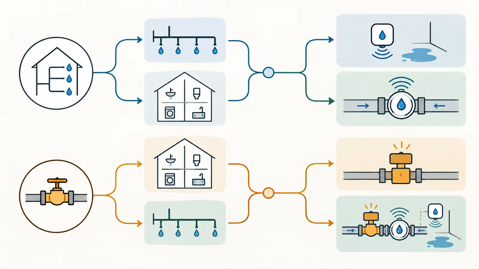
Before plumbing rough-in, draw the water topology from source to end use, label every branch relative to the proposed valve, and assign each branch one response state: monitored, intentionally excluded, or separately sensed. The map must show service-line size, meter and PRV position, all split points, automatic users, fire sprinklers, irrigation and the accessible manual shutoff. A device cannot be sized, placed or commissioned against a floor plan alone.
Gather the minimum inputs
The homeowner can gather many inputs without opening walls or manipulating equipment. Bring these to the designer and plumber:
| Input | Unit or record | Homeowner collection method | Professional verification |
|---|---|---|---|
| Service-line nominal size | inch or DN; record source of size | Utility documents, civil/site plan or proposed plumbing plan | Plumber confirms the actual connection and selected device compatibility |
| Utility meter location | plan location and measured access distance | Site plan, utility markout and photos where permitted | Utility and plumber confirm service-side limits and access |
| Primary manual shutoff | location, valve type and label | Mark the room, wall and height on plan | Plumber confirms serviceability and sequence |
| Pressure-reducing valve (PRV) | present/absent, location and model if known | Plumbing schedule or site observation | Plumber confirms pressure arrangement and device limits |
| Proposed device location | room, wall, elevation, clear working zone | Mark the utility-room plan and a service path | Plumber confirms pipe geometry, support and model clearance |
| Irrigation branch | branch point, meter/backflow arrangement, intended monitoring | Site/civil plan and irrigation scope | Plumber, irrigation designer and utility/AHJ resolve placement and rules |
| Fire-sprinkler branch | branch point, designer and intended protection state | Fire-protection drawings and builder scope | Fire-sprinkler designer and actual AHJ verify; do not self-approve |
| Treatment | softener, filter, RO, UV or other unit; inlet/outlet | Equipment schedule and owner preference | Plumber confirms bypasses, drains, power and maintenance space |
| Automatic appliances | water heater, boiler fill, humidifier, ice maker, appliance, pool fill or other use | Mechanical and appliance schedules | Plumber/HVAC professional confirms normal cycles and branch consequence |
| Point-sensor zones | room, appliance, sensor type, cable path and access | Risk map based on planned equipment | Installer confirms sensor suitability and protection from tampering |
| Pipe length | inches or feet of straight or usable run | Scale the plan; do not estimate from device marketing | Plumber measures against exact installation guide |
| Electrical provision | voltage, outlet location, circuit/connection plan and continuous-power requirement | Mark desired outlet and control location | Electrician designs and installs to applicable rules |
| Connectivity | Wi-Fi band/path or local control, signal location and owner account | Identify router/network area and service plan | Integrator or electrician confirms usable connection and handoff |
| Manual recovery | valve handle/override, label, tool need, safe access | Write a plain-language recovery step | Plumber confirms model-specific procedure and safe order |
| Owner records | model, serial, revision, warranty, subscription and photos | Create a project record row | Builder and installer complete turnover packet |
The map must distinguish a proposed branch from a verified branch. A line shown on an early plan may be rerouted by the plumber. A fixture schedule may omit a drain, makeup-water line or automatic fill connection. The correct handoff is not “the plumber knows”; it is a marked drawing or redline that records the as-installed topology and the person who verified it.
Draw the sequence, not just a collection of labels
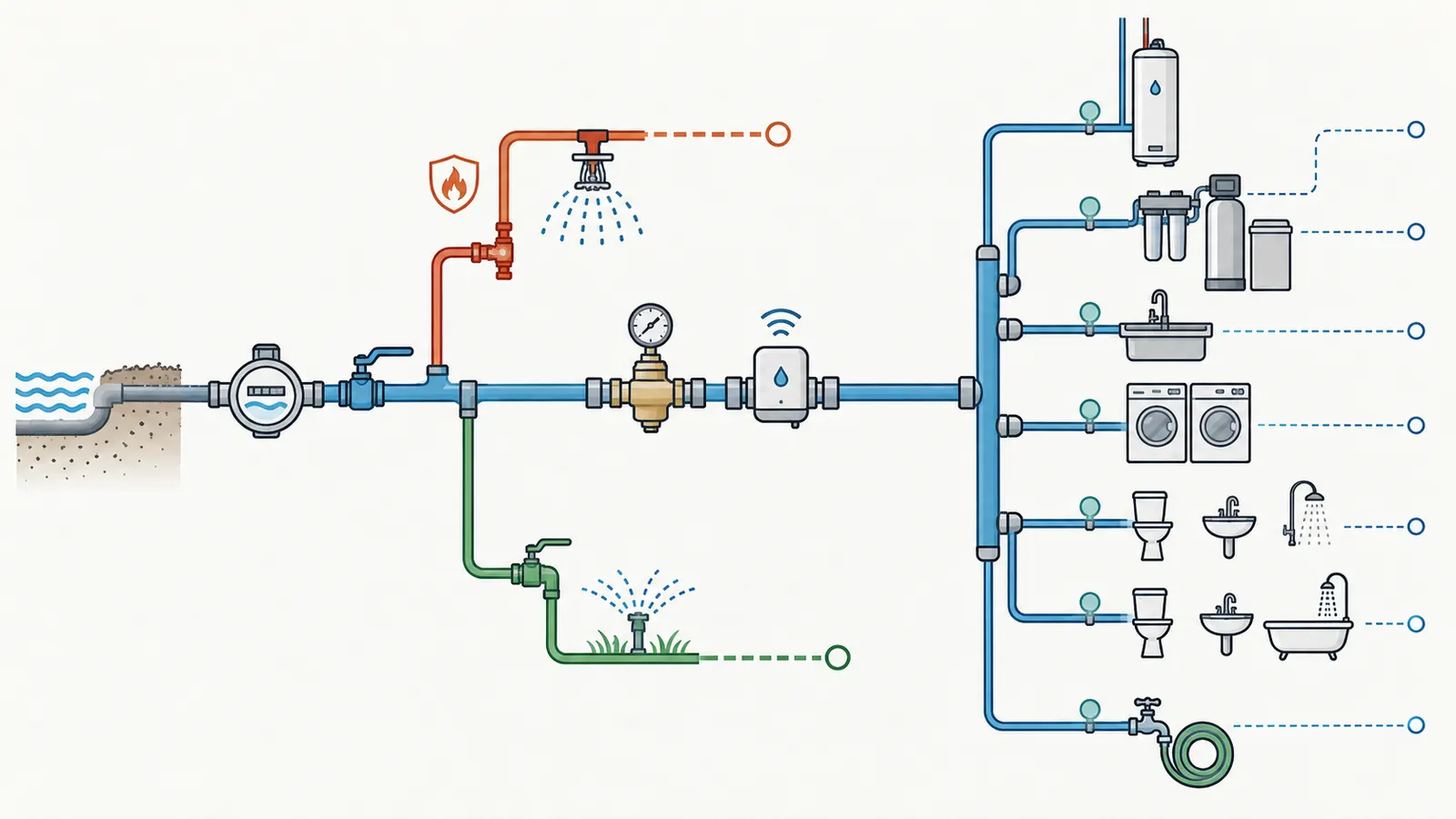
Use a simple left-to-right or top-to-bottom sequence. This is an illustrative map for a hypothetical municipal-supply home, not a design to copy:
street service -> utility meter -> utility-side/manual limits -> primary manual shutoff
                                      |
                                      +-> fire-sprinkler branch [separate protection / no domestic auto-close assumed]
                                      |
                                      +-> irrigation branch [included, excluded, or separately monitored: unresolved]
                                      |
                                      +-> PRV -> proposed whole-home device -> indoor domestic manifold
                                                                      |
                                                                      +-> water heater
                                                                      +-> kitchen / laundry
                                                                      +-> bathrooms
                                                                      +-> treatment equipment
                                                                      +-> hose bibs or other exterior branch
                                                                      +-> point-sensor zones
The map becomes a decision tool only after each branch receives a state and owner. For example, “irrigation branch” is not complete. Its row should say: “excluded from automatic closure; flow visible at the utility meter only; separate irrigation leak plan owned by landscape contractor,” or “included downstream of device; irrigation controller and normal cycles must be recorded for calibration.” The map should also identify whether an exterior hose bib is before or after the proposed valve. If it is after the valve, an open hose can look like a leak or keep the home from becoming truly protected; if it is before the valve, the device cannot close it.
Classify branches with three explicit states
Use exactly one primary state for each water branch:
| State | Meaning | Required note | Example next action |
|---|---|---|---|
| Monitored | The selected device or sensor is intended to observe the branch | Name the sensing method and the device zone | Plumber confirms topology; installer verifies an expected event appears in the controller |
| Intentionally excluded | The project accepts that the selected device will not monitor or close the branch, or leaves it available for a stated reason | State why, who owns it and what separate protection exists | Fire-sprinkler designer confirms the protection state; irrigation owner supplies separate shutoff or monitoring plan |
| Separately sensed | The branch is outside the main inference or valve response but receives a point sensor, cable, submeter or separate control | Name sensor, location, power/battery and alert owner | Reserve access and test the alert path with the responsible trade |
Add a fourth internal status, unresolved, during design. Do not deliver unresolved rows as one of the three final states. A branch with an unknown split point is not “monitored by default.” It is a release blocker.
Treat fire sprinklers as a separate protection decision
The fire-sprinkler branch is the most important exception to a casual whole-home shutoff concept. The homeowner should not decide that a valve is safe merely because its product page says whole-home. EPA’s WaterSense guidance says to ensure an in-line device does not interfere with fire sprinkler systems. The Watts/Sentinel manual says its Leak Defense valve must be downstream of its fire-sprinkler line in the described arrangement and warns that a layout that differs from the diagram needs system-specific recommendations. That evidence establishes why the branch must be identified; it does not establish what the AHJ will accept in a particular state, county or city.
The handoff should contain:
- the fire-sprinkler designer’s name and drawing revision;
- the branch point relative to meter, manual shutoff, PRV and leak device;
- whether domestic leak detection observes the branch;
- whether an automatic action can close the branch;
- the required normal valve state and supervision, if any, as determined by the responsible fire-protection parties;
- the actual AHJ and the permit or review record, if one is required;
- the recovery instruction for a domestic alert that must not compromise fire protection.
If this information is missing, choose a plan state of “fire-sprinkler coordination open,” not “combined system approved.” Remote photos or a markup cannot substitute for the local fire-protection and AHJ decision. The reader can collect drawings and ask questions; the fire-sprinkler designer and AHJ own the technical and approval decision.
Include treatment and automatic users in the map
Water softeners, reverse-osmosis units, filters, booster arrangements, automatic pool fill, humidifiers, ice makers and other equipment may have normal or intermittent water movement. The Watts/Sentinel pre-installation survey explicitly calls out reverse osmosis, water softeners, irrigation, automatic pool fill, outside hose bibs, booster pumps and other automatic water users as downstream conditions that may require accessories or a different valve position. Use that list as a prompt to inspect the actual home, not as proof that a different manufacturer behaves the same way.
For each automatic user, record:
- its normal operating window and expected duration, if the equipment manufacturer provides one;
- whether it is upstream or downstream of the proposed valve;
- whether a point sensor can detect a failure at the equipment;
- whether the system has an approved or manufacturer-described bypass, accessory or calibration process;
- who will explain its normal behavior during commissioning;
- what happens if the automatic valve closes while the equipment is operating;
- how the owner restores the equipment after an alert.
Do not invent a flow threshold from a fixture count. The exact device may learn patterns, use pressure analysis, use a trip rate, or require sensitivity settings. A plumbing plan can identify the event that needs consideration; it cannot prove that a selected algorithm will classify it correctly.
Compare the four architectures with a recorded decision #
Compare candidate architectures against the same home-specific criteria: coverage, intervention, branch compatibility, false-shutoff consequence, access, power, connectivity, manual recovery, point specificity, maintenance and turnover. Score only entered project assumptions; do not treat a manufacturer’s marketing phrase as an independent performance measurement or promise.
Use a decision matrix with hard gates first
The hard gates come before weighted preferences. Reject or redesign a candidate when any answer is “no” in a safety or physical-compatibility row:
| Hard gate | Pass condition | Evidence or record required | Typical owner |
|---|---|---|---|
| Branch topology | All water branches are mapped relative to the proposed valve and sensors | Redlined plumbing diagram with branch states | Plumber and builder |
| Fire protection | Fire-sprinkler branch is explicitly coordinated and not unintentionally disabled | Fire-sprinkler review and actual AHJ record where applicable | Fire-sprinkler designer, builder and AHJ |
| Product fit | Exact model accepts the proposed pipe size, pressure, temperature, connection, orientation and water service | Current product page, installation guide and submittal | Plumber and supplier |
| Service access | A person can reach the valve, sensor, power connection, controller and manual recovery point for service | Dimensioned utility-room layout and access path | Designer, plumber and builder |
| Power | The exact device’s required power is available continuously and installed by the responsible electrical trade | Electrical plan, outlet/circuit record and test result | Electrician |
| Connectivity/control | The chosen alert and control path is available where the device is installed, or local operation is intentionally sufficient | Network/control record and account owner | Electrician, integrator or builder |
| Recovery | A labeled manual or local method exists and the owner can follow it safely | Recovery card, commissioning record and demonstration | Plumber and installer |
| Turnover | Model, serial, revision, warranty, subscription, credentials process and maintenance schedule are recorded | Handover packet | Builder and installer |
Only candidates that pass the hard gates should receive preference scores. A point-sensor-only plan may pass if the homeowner deliberately accepts that it cannot detect a concealed leak outside each footprint. A combined plan may fail if it closes a required branch without a confirmed protection decision. The matrix does not reward complexity; it makes the consequence of simplicity visible.
Score preferences transparently
For a candidate that passes the hard gates, use a five-factor illustrative score. Rate each factor from 1 to 5 using project-specific notes:
- C, coverage: 1 = a few named points; 5 = the intended water paths are broadly observed, with exclusions documented.
- I, intervention fit: 1 = alarm only where closure is required; 5 = the intended response can safely close the selected branch and leave recovery available.
- A, access and maintainability: 1 = difficult or concealed service; 5 = dimensioned, labeled and reachable.
- R, resilience: 1 = one unowned power/network dependency; 5 = the planned local and remote behavior remains understandable when a dependency is unavailable.
- T, turnover clarity: 1 = no model or training record; 5 = model revision, warranty, account, test and owner instructions are complete.
The illustrative weighted score is:
Score = 0.30C + 0.25I + 0.20A + 0.15R + 0.10T
The weights are a Brictale planning choice, not an industry standard. Coverage receives the largest weight because a device that cannot observe the intended branch does not solve the stated problem. Intervention receives the next largest because an unsafe or nuisance-prone closure can create a different failure. Change the weights if the household has a documented priority, and write the reason beside the formula.
Worked example: a modeled, illustrative comparison
The following is an illustrative example for a hypothetical 2,400-square-foot, two-story home with municipal water, a proposed 1-inch service line, one indoor domestic branch, a separate irrigation branch, a fire-sprinkler branch, a water softener, a tank water heater, a refrigerator connection, a washing machine, and a utility-room device location. These are modeled inputs, not measurements of a real home, not a quote and not a test. The example assumes the homeowner wants remote alerting, wants the indoor domestic branch to close automatically when safe, and wants local moisture confirmation at the laundry and water-heater zones.
| Candidate | C | I | A | R | T | Calculation | Illustrative score |
|---|---|---|---|---|---|---|---|
| Point sensors only | 2 | 1 | 4 | 4 | 3 | 0.30(2)+0.25(1)+0.20(4)+0.15(4)+0.10(3) | 2.55 |
| Whole-home flow monitor, no closure | 4 | 2 | 4 | 3 | 3 | 0.30(4)+0.25(2)+0.20(4)+0.15(3)+0.10(3) | 3.25 |
| Automatic shutoff with selected point sensors | 4 | 4 | 4 | 3 | 4 | 0.30(4)+0.25(4)+0.20(4)+0.15(3)+0.10(4) | 3.85 |
| Combined flow, shutoff and point sensors | 5 | 4 | 3 | 3 | 4 | 0.30(5)+0.25(4)+0.20(3)+0.15(3)+0.10(4) | 3.95 |
The combined row is not automatically selected. It scores only after the hard gates pass. In this example, the score is close to the selected-shutoff row, so the homeowner should ask whether the extra controller, sensor batteries, network setup and maintenance are worth the additional point information. If the fire-sprinkler branch is still unresolved, both rows fail the hard gate regardless of score. If the owner is frequently away, resilience and turnover might be weighted more heavily. If the utility room is tight, access may reduce the combined row.
Show sensitivity instead of pretending the score is objective
Sensitivity tests how the choice changes when a material assumption changes. Keep the same formula and alter one input at a time. For the illustrative example:
| Sensitivity case | Changed input | Combined row calculation | Result |
|---|---|---|---|
| Base case | C=5, I=4, A=3, R=3, T=4 | 0.30(5)+0.25(4)+0.20(3)+0.15(3)+0.10(4) | 3.95 |
| Tight access | A falls from 3 to 1 until layout is redesigned | 0.30(5)+0.25(4)+0.20(1)+0.15(3)+0.10(4) | 3.55 |
| Better local recovery | R rises from 3 to 4 after a local controller and labeled manual path are confirmed | 0.30(5)+0.25(4)+0.20(3)+0.15(4)+0.10(4) | 4.10 |
| No useful point zones | C falls from 5 to 4 because laundry and water-heater sensors cannot be placed | 0.30(4)+0.25(4)+0.20(3)+0.15(3)+0.10(4) | 3.65 |
| Turnover not accepted | T falls from 4 to 1 because the installer will not provide model and training records | 0.30(5)+0.25(4)+0.20(3)+0.15(3)+0.10(1) | 3.65 |
The point is not that 3.95 is “good.” The point is that access, recovery and turnover can move the decision materially. A candidate with a lower preference score but clean hard gates may be a better build decision than a feature-rich candidate that cannot be serviced. Record the original inputs, the changed input, the formula and the reason for the change in the project decision log.
Apply the matrix to actual candidate documents
For each candidate, save the exact model and revision, not just a web page title. The EPA WaterSense technical sheet advises understanding product limitations, including conditions such as higher pressure or meter compatibility, and selecting a device capable of monitoring all intended water use. Its guidance also says that in-line devices are more invasive and likely require a plumber, while moisture or external-flow devices are less complicated to install. Use that distinction to ask whether the project is reserving a plumbing intervention or merely a sensor location.
The Moen Flo installation guide INS11955B illustrates why this matters. It specifies that the Flo Shutoff is installed in-line on the main cold-water supply, requires a nearby continuously powered outlet, and specifies arrow orientation in the installation guide. Moen's current support page recommends using a plumbing professional because installation removes a section of the main water pipe. The support page also describes 2.4 GHz Wi-Fi and app control, while INS11955B says an energized device without internet enters local mode and may experience frequent water interruptions until connected. The same guide requires a weather-resistant enclosure at least 12 inches above grade for outdoor installation. If this model is selected, connectivity and environmental placement are not optional post-handover details; they belong in the rough-in and turnover plan. Verify the current model revision before installation.
Resideo’s current L5 installation instructions 33-00607EFS—08 are a different product-specific example. They list the VWS01Y-1 as a 1-inch NPT variant, describe app control and manual or emergency handle control, and specify an any-orientation ball valve, a 10-foot power adapter and a 100–240 V adapter input. The instructions also say the product is for indoor use and must not be installed on a fire-sprinkler or suppression system. That does not make it interchangeable with a Moen Flo or a Watts/Sentinel system. The candidate record must still show the proposed service-line size, valve location, branch topology, network owner and manual procedure from the current L5 installation materials.
Uponor’s Phyn Plus page describes a single supply-line device with automatic shutoff, notifications, remote control, daily pressure and tiny-leak checks, and usage insights by categories such as showers, toilets and irrigation. Treat those as manufacturer-described capabilities. The page does not provide independent performance testing or prove that every leak will be located, classified or stopped. The comparison should ask which claimed behavior matters to this home and how the installer will verify it.
Reserve pipe, access, power, control, and recovery space #
Reserve the exact installation envelope before rough-in: the correct pipe path and length, service access, dry power, control or network location, sensor routes, labels and a manual recovery method. The EPA WaterSense technical sheet specifically calls for enough pipe length and easy access for an in-line device; manufacturer values then control the selected model. A device that technically fits between two fittings may still be a poor plan if the owner cannot see its status, unplug it as instructed, replace a sensor, or reach the manual valve.
Place the valve after the right upstream components
Valve placement is a topology decision, not a preferred room. Start from the exact product’s installation guide and draw the upstream sequence. Common inputs to resolve include the utility meter, primary manual shutoff, PRV, backflow equipment, irrigation split, fire-sprinkler split and treatment equipment. The selected location must also respect utility access and any local requirement identified by the actual utility or AHJ. Do not convert a manufacturer’s “typical garage, basement or crawl-space location” into a national placement rule.
The Watts/Sentinel manual states that its valve is on the main water line downstream of the primary shutoff, pressure regulator, irrigation line and fire-sprinkler line in its described configuration. It also notes that some utilities require a minimum distance downstream of the meter and that a bypass may be recommended. Those are product and utility-scope prompts. Ask the actual utility and plumber whether the proposed location is permitted and serviceable for the project address.
The Moen INS11955B installation guide adds a service detail that is easy to lose after rough-in: retain the installation spacer in case the Flo device must later be removed from the line. If the project has selected that model, the spacer belongs in the turnover packet and the access plan should allow removal without demolishing finished work. The guide also gives a continuous-pressure recommendation of no more than 80 psi. The plumber must compare that limit with the actual pressure arrangement; the homeowner should not use a device’s app reading as a substitute for the plumber’s pressure decision.
For a device with a sizeable actuator or flow body, draw the body length, connection depth, actuator height and tool swing. The Watts/Sentinel manual publishes dimensions for its named sizes and warns that bracing may be required if the plumbing cannot support the weight. Use the exact selected size and the plumber’s support detail. A scaled plan should show:
- centerline and flow direction;
- upstream and downstream manual isolation points;
- device body and actuator envelope;
- unions or other service connections if specified;
- pipe supports or bracing;
- drain or spill protection where the designer requires it;
- wall or panel opening, if needed;
- clear reach for status, reset and manual override;
- a dry location for the power connection;
- adjacent equipment that could block removal.
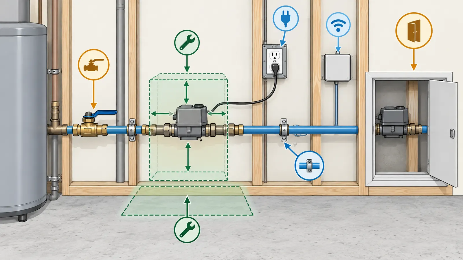
Do not bury an actuator behind a water heater, storage shelving or a fixed panel. “Accessible” means more than technically visible through a removable ceiling tile. The owner and service technician need to identify the valve without moving dangerous or heavy objects, and the installer needs room to work without damaging another system.
Match power to the exact device
Power is a design input with a voltage, location, distance, continuity and owner. It is not enough to draw “outlet near valve.” The Moen Flo INS11955B guide specifies a continuously powered 100–240 VAC outlet within 10 feet of the installation and says outdoor installation needs a weather-resistant enclosure at least 12 inches above grade. The Watts/Sentinel manual specifies a dry non-switched 120 VAC outlet, a 24 VAC transformer run no longer than 100 feet, and a separate outlet within 6 feet of its wireless panel. The Resideo L5 instructions identify a 100–240 V adapter input and a 10-foot power adapter for the named model. These values are not interchangeable.
Give the electrician a device submittal with:
- model number and revision;
- required input voltage and frequency;
- adapter or transformer type;
- cord or low-voltage length;
- outlet or connection location;
- dry, weather-resistant or other environmental condition in the product documents;
- whether the outlet is intended to remain continuously energized;
- how the device behaves when power is interrupted;
- whether a battery backup or generator strategy is proposed;
- who tests power and records the result.
The electrician decides the compliant wiring method for the actual jurisdiction. This article does not tell a homeowner to run line-voltage wiring, modify a circuit, install an outlet, conceal a cable or work in a wet location. The safe homeowner action is to mark the desired device and controller locations and ask the electrician to confirm the electrical plan, required protection and test record.
The Watts/Sentinel manual recommends a battery backup or generator in locations prone to power outages, but that recommendation is not proof that a given system remains leak-protective without power. Ask the manufacturer what detection, alerting, valve position and manual operation are available during a power loss. Write each behavior in the recovery record. A claim that the valve “fails safe” is incomplete unless “safe” is defined for domestic water, fire protection, occupants, equipment and the owner’s ability to restore water.
Plan connectivity and local control together
Remote alerts are useful only if someone owns the account, the device is connected, the household knows what a notification means and local control remains understandable. Record the network path without assuming the homeowner’s future router will be in the same location. A 2.4 GHz requirement, a panel-to-valve distance, a wireless control zone or a subscription may change the rough-in plan.
Moen’s current support page says the Flo Shutoff uses a 2.4 GHz Wi-Fi connection and can be controlled remotely through the app. Its INS11955B installation guide warns about local mode when internet is unavailable. The Watts/Sentinel manual specifies a control panel within 100 feet of the valve and recommends 50 feet or less for reliable connection; it also describes a local panel for water off/on, scenes, trip rates and status. Resideo’s current L5 instructions describe app control and manual override. Uponor describes SMS and push notifications and remote shutoff for Phyn Plus. These are different control paths, so record the exact one selected.
The rough-in handoff should answer:
- Where is the router or access point relative to the device?
- Is a wired network, wireless signal, local panel or app required?
- Who creates the device account: builder, installer or homeowner?
- Who receives alerts while the owner is away?
- What happens to local operation when internet is down?
- Can a plumber service the device without the owner’s phone?
- What credentials or transfer steps are allowed at turnover?
- Does a subscription exist, and if so, what service stops when it ends?
- Where is the controller mounted so the owner sees it and can operate it?
Do not put network passwords in an open construction log. Record the account transfer process, device identifier and support path, then let the owner set or change credentials. The builder should deliver a secure turnover instruction rather than a shared password written on a plan.
Make manual recovery a first-class requirement
Every automatic shutoff needs a recovery decision: how to confirm the cause, how to stop or reopen the valve, who is allowed to manipulate it, and what remains protected while the domestic water is off. The owner should not have to search an app while water is needed for an urgent safe action, and a service worker should not guess which valve is the automatic one.
For the Watts/Sentinel system, the manual says to disconnect power before attempting manual operation and gives different override procedures for systems 1.5 inches or smaller versus 2 inches or larger. For Moen, the support page says the valve can be turned back on through the app or manual switch after the cause has been checked. For Resideo’s current L5 instructions, manual override is identified as a feature, with the emergency handle intended for emergencies such as a power outage. These statements are model-specific. The installer must demonstrate the actual procedure for the actual size and revision and leave the current manual with the homeowner.
The recovery card should say, in plain language:
- how to identify an alert or shutoff event;
- how to look for visible water without entering an unsafe area;
- what not to touch, including electrical equipment or a suspected contaminated area;
- when to call the plumber, electrician, fire-sprinkler professional, utility or emergency service;
- how to close or reopen the valve using the documented local method;
- what happens to irrigation, treatment, water heating and fire sprinklers;
- how to confirm the valve’s position and check the installation area for leakage;
- how to record the event and reset any temporary mode;
- how to restore ordinary monitoring after a test or maintenance operation.
If the owner cannot safely perform the documented non-hazardous recovery step, the next decision is whether a local control, accessible manual valve, professional service agreement or different architecture is needed. Automatic control is not a substitute for a reachable primary manual shutoff.
Sequence the design and trade handoffs before rough-in #
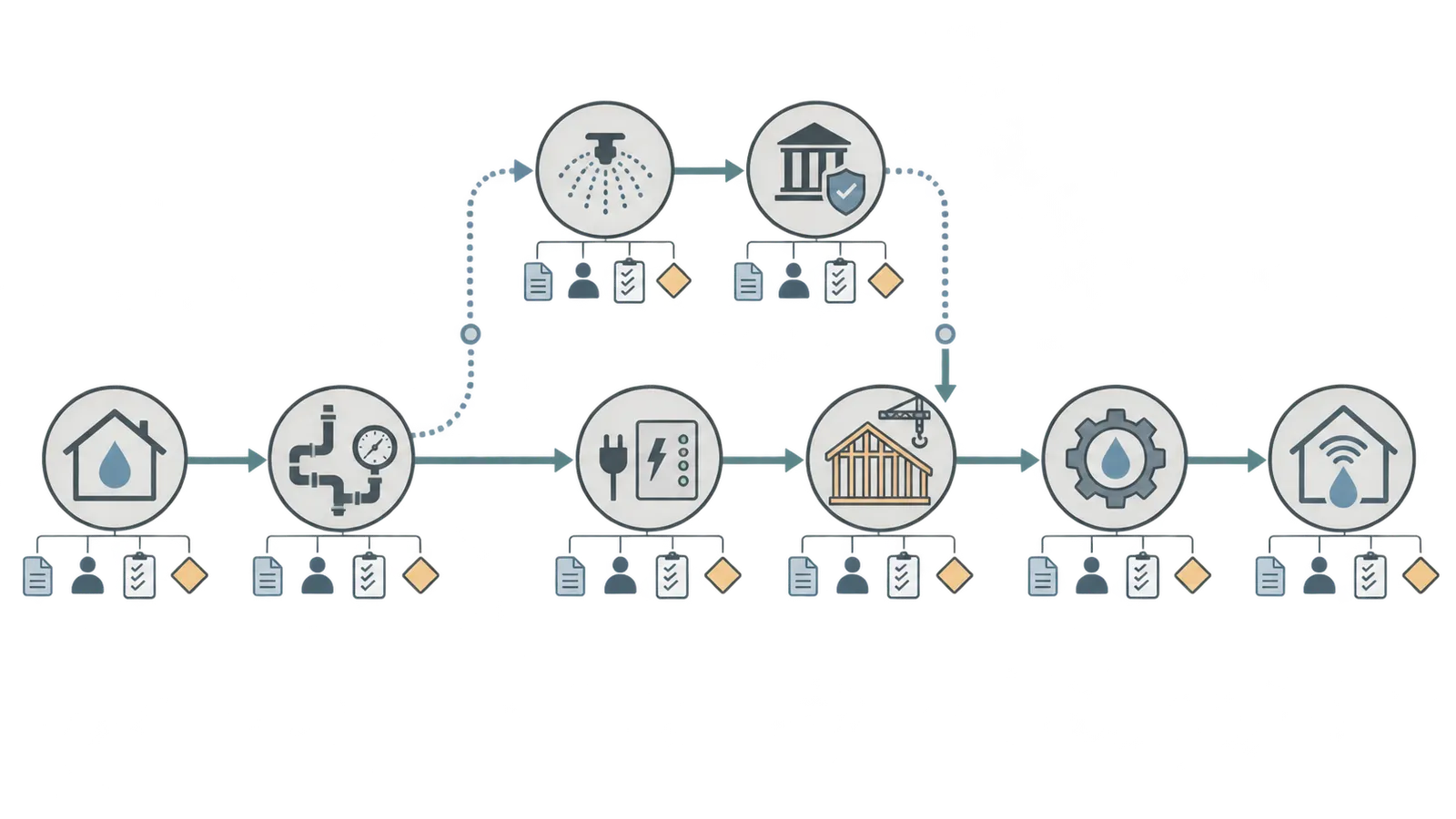
The correct sequence is to freeze the decision record before the plumbing crew closes the opportunity: define the outcome, map branches, select a candidate, issue exact product documents, reserve pipe and utilities, coordinate fire protection, rough in, verify before concealment, commission after utilities are live, and hand over the record. The homeowner coordinates decisions; qualified trades own their technical work.
Use this project sequence
1. Write the desired response
State whether the home needs alerting, local alarm, remote notification, automatic closure, point confirmation, or a combination. State whether the target is indoor domestic water, all property water, or a set of named branches. State what must remain continuously available. A phrase like “whole-home leak protection” is not sufficient until it is replaced by branches and actions.
2. Build the branch register
Use the architectural, plumbing, mechanical, landscape and fire-protection drawings together. Ask for all water use, including equipment that is not a room fixture. Mark the proposed meter, main shutoff, PRV, branch splits, treatment units, hose bibs, fire sprinklers, irrigation, automatic fill and sensor zones. Record unknowns as unresolved.
3. Request current model documents
For each candidate, save the product page, installation guide, data sheet, owner guide, warranty, power requirement, size table, pressure/temperature limit, orientation, clearances, manual recovery, control behavior and maintenance instructions. Put the retrieval date and model revision in the decision log. EPA warns that products have unique installation requirements and limitations, including possible pressure or meter incompatibility. Do not compare a current product page with an old manual without noting the mismatch.
4. Hold a responsibility review
The plumber reviews pipe topology, size, pressure, valve position, unions, supports, bypass or isolation and leak checks. The electrician reviews power and any low-voltage pathway. The builder coordinates schedule, access, concealed-work release and records. The fire-sprinkler designer reviews any sprinkler branch. The homeowner chooses the intended response, approves the scope and receives training. A network integrator or manufacturer support team may assist with connectivity and calibration, but assistance does not transfer the builder’s or installer’s record duties unless the contract says so.
5. Issue the rough-in markups
The plumbing plan should show the device body and flow arrow, not merely a box labeled “future smart valve.” The electrical plan should show the correct power provision. The utility-room elevation should show access. The sensor plan should name zones and cable routes. The fire-protection plan should show its branch relationship. Each markup should include the exact model or the minimum reserved envelope if the product is not yet purchased.
6. Verify before concealment
Before insulation, drywall, cabinets or fixed equipment conceal the area, photograph the installed topology, measure the device location, confirm the outlet and controller route, inspect support and access, and save the current product documents. If the installer changed the branch or location, update the matrix and re-run hard gates. A field change is a new decision, not a cosmetic redline.
7. Commission after water, power and network are available
The installer performs the exact product’s commissioning steps, checks for plumbing leakage, confirms valve movement, calibrates or learns only as the manufacturer directs, tests local and remote controls, and records the result. The owner watches the demonstration and receives the manual, model, serial, warranty and maintenance record.
Assign responsibility explicitly
| Deliverable | Homeowner | Builder/general contractor | Plumber | Electrician | Fire-sprinkler designer/AHJ |
|---|---|---|---|---|---|
| Desired response and branches the owner wants protected | Approves | Coordinates | Advises feasibility | Advises utility impact | Advises protection conflict |
| Service-line, meter, PRV and valve topology | Supplies project information | Coordinates drawing | Designs/installs/records | — | Reviews sprinkler relationship |
| Exact device selection | Makes owner decision with documented trade advice | Tracks submittal | Confirms pipe and pressure fit | Confirms power fit | Reviews fire-protection impact |
| Sensor zones and controller location | Identifies risk priorities | Coordinates room/elevation | Confirms water exposure | Confirms power/low voltage/network path as assigned | — |
| Power outlet or circuit | Approves scope | Schedules | Identifies device need | Designs, installs and tests | — |
| Fire-sprinkler separation or supervision | Receives explanation | Schedules review | Provides plumbing layout | — | Owns technical review; AHJ owns approval where applicable |
| Concealed-work photos and as-built redline | Receives | Collects and stores | Supplies plumbing redline | Supplies electrical record | Supplies applicable fire record |
| Commissioning and calibration | Observes and signs receipt | Confirms completion | Operates plumbing/device procedure | Confirms power/control | Confirms sprinkler state where applicable |
| Warranty and subscription handoff | Accepts account and records | Delivers packet | Delivers installation record | Delivers electrical test record | Delivers applicable closeout record |
This table is a scope aid, not a contract. The contract should name the legal parties, deliverables, exclusions, correction responsibility, schedule and payment terms. If the builder says “owner supplied,” clarify whether that includes product selection, delivery, model revision verification, plumber labor, electrician labor, network setup, sensors, batteries, commissioning and warranty registration. A supplied device sitting in a box is not a commissioned system.
Put the comparison into bid scope
Ask each bidder to price the same scope fields:
- exact device model and size;
- fittings, unions, adapters, supports and enclosure;
- pipe cutting or rerouting;
- primary and secondary isolation points;
- bypass, if the selected manufacturer or plumber recommends one;
- fire-sprinkler and irrigation coordination;
- treatment and automatic-appliance accessories or calibration;
- point sensors, cable length, batteries and labels;
- power outlet, transformer, low-voltage or network provisions;
- controller, app setup and account handoff;
- startup, leak check, calibration and test events;
- photographs, as-built redline, serial number and warranty record;
- future removal path and retained spacer where applicable;
- exclusions, including local permit or AHJ fees if not included;
- maintenance tasks, battery schedule and support contact.
The bid should identify the unit for each allowance: one valve, one controller, one sensor, one branch, one linear foot of cable, one hour of setup. Do not compare one quote that includes an electrician and fire-protection coordination with another that excludes both. If the selected architecture changes a wall, cabinet, utility panel or equipment layout, carry that consequence into the broader Brictale homeowner blog record and the project budget rather than treating it as a last-minute smart-home accessory.
Verify commissioning, recovery, and failure modes #
Release the system only after the installed device, sensors, valve response, power, controls, branch behavior, recovery path and records have been tested against the selected model’s current instructions. Commissioning must test the actual failure modes that matter to this home; a green status light or an app download is not proof that water is sensed, the correct valve closes, the excluded branch remains protected, or the owner knows what to do.
Use a pre-concealment release checklist
Mark each row pass, fail or not applicable, with a person and date. “Not applicable” needs a note; it is not a blank.
| Release gate | Pass test | Evidence to retain | If it fails |
|---|---|---|---|
| Model identity | Installed device matches approved model and current instructions | Photo of label, model, serial and document revision | Stop commissioning; recheck compatibility and scope |
| Branch topology | As-installed redline matches the decision map | Marked drawing and plumber signoff | Reclassify branches and re-run hard gates |
| Fire protection | Sprinkler branch state is documented by responsible parties | Fire drawing/review record and AHJ record where applicable | Do not activate domestic auto-close until resolved |
| Valve position | Flow direction, upstream sequence and service connections match guide | Photo and plumber record | Correct before concealment or commissioning |
| Pipe and support | Required length, connections and support are present | Measurement and photo | Redesign; do not force the device into a short or unsupported run |
| Access | Manual, actuator, sensor, power and controller can be reached | Utility-room photo and access measurement | Move equipment or create a service opening before finishes |
| Power | Correct continuous supply is present and tested by electrician | Electrical test record | Leave device uncommissioned; resolve with electrician |
| Connectivity | Intended local/remote control path works | Controller/app status and account transfer record | Document local fallback and resolve network gap |
| Valve movement | Close, open and status response work as the guide directs | Commissioning time and observation | Isolate and call installer/manufacturer support |
| Point sensors | Each zone detects the planned test event | Sensor-zone log | Reposition, replace or reclassify the zone |
| Flow learning/calibration | Device-specific learning, calibration or sensitivity setup is complete | Settings or calibration record | Do not claim protection is active until the process is complete |
| Normal water users | Toilets, fixtures, treatment and automatic appliances operate without unexplained alerts | Event log and exception list | Adjust only per manufacturer; investigate nuisance events |
| Manual recovery | Owner can identify and use the safe documented local method | Demonstration acknowledgement | Add training or change architecture |
| Maintenance | Batteries, filters, inspections, subscription and support are recorded | Maintenance schedule | Assign an owner and due date |
| Turnover | Manual, warranty, model, serial, photos, account transfer and as-built map delivered | Handover index | Hold closeout for missing documents |
EPA’s WaterSense material says to confirm the location and installation of leak-detection devices and to communicate subscription requirements at turnover. The Watts/Sentinel manual gives a more detailed product example: its actuator should close and reopen, its panel shutoff feature should be confirmed, and calibration values should be recorded for warranty validation. Use those as source-derived prompts, while using the exact selected product’s procedure for the actual test.
Test the expected events without creating a hazard
The homeowner can observe and document controlled tests that the installer has approved. The homeowner should not deliberately flood a room, spray electrical equipment, disconnect fire-protection equipment, manipulate a pressure device, open a concealed fitting, or create a condition that could contaminate a space. A qualified installer should select the test method and perform any work requiring tools, water isolation, electrical access, pressure manipulation or access to equipment.
Useful test records include:
- a small, controlled moisture test at a point sensor using the manufacturer’s approved method;
- a normal fixture flow event and a note that it appeared as expected;
- a controlled valve close and reopen from the local control;
- a remote alert test if the product supports it;
- a power interruption observation, only if the manufacturer and electrician approve the procedure;
- a network outage or local-control explanation, without assuming a test result proves all future outage behavior;
- a treatment or automatic-appliance cycle observed by the responsible professional;
- a manual recovery demonstration with the valve model and size written down.
Record the date, tester, starting valve state, event, observed alert, observed valve response, excluded branches, abnormal result, corrective action and retest. A test that was skipped because the network or utility was not ready is an open gate, not a pass.
Check common failure cases by branch
| Failure case | What the homeowner may observe | What it does not prove | Safest next step | Bring to professional |
|---|---|---|---|---|
| Device sees no flow during a normal fixture use | App or controller remains unchanged | It does not prove the fixture has no water or the pipe is correctly connected | Stop the test and ask installer to verify flow direction, wiring, sensor state and branch inclusion | Model, status photo, fixture used, time and redline |
| Nuisance shutoff during normal use | Water closes during a toilet fill, treatment cycle, irrigation event or appliance operation | It does not prove the algorithm is defective or that the event is safe to ignore | Keep the valve in the documented recovery state and have the installer investigate the normal-use profile | Event history, appliance cycle, settings and branch map |
| Alert arrives but the room is unknown | Notification says abnormal use or leak | A main-line monitor may not locate the exact leak | Inspect only accessible, safe areas; call the plumber if the source is not obvious | Alert time, valve state, visible observations and photos from a safe distance |
| Point sensor stays silent | No alarm at the chosen appliance or cable zone | It does not prove the area is dry if the sensing footprint is misplaced, dirty or unpowered | Have the installer perform the approved sensor test and check battery, cable and placement | Zone ID, sensor model, battery date and test result |
| Valve closes but an exterior branch still flows | Hose bib or irrigation remains supplied | The valve may be correctly closing only its downstream branch | Do not assume protection; confirm branch topology and separate shutoff ownership | Valve location, flow observation and as-built drawing |
| Fire-sprinkler branch is on the wrong side of the valve | Drawing and field piping disagree | It does not prove the sprinkler system is unsafe, but it is an unresolved protection conflict | Stop automatic operation and contact fire-sprinkler designer, plumber and AHJ as applicable | Photos, plans, device guide and jurisdiction/address |
| Internet is unavailable | Remote alert/control does not respond or device behaves differently | It does not prove the local valve is open or closed | Use the documented local status/recovery method; do not guess from the app | Network state, local indicator and manual procedure |
| Power is interrupted | Controller or valve loses normal status | It does not prove what the device will do in every outage | Follow the manufacturer’s outage instructions and call the electrician/installer | Power test record, device state and exact model |
| Access is blocked after finishes | Service person cannot reach valve or outlet | It does not prove a removable panel is adequate | Treat it as a construction defect or coordination change before closeout | Utility-room photo, measured obstruction and scope owner |
| Product is replaced with a similar model | New box appears to fit the same pipes | Similar size or brand does not prove pressure, power, control or warranty equivalence | Reopen submittal review and update all trades before installation | Old/new model, guides, dimensions and compatibility questions |
Do not diagnose a concealed plumbing leak from a screenshot or photograph. Brictale cannot remotely determine whether a wet area contains contaminated water, electrical danger, structural damage or another hazardous condition. Remote guidance also cannot assess or authorize entry into crawl spaces, pits, tanks, vaults or other confined spaces; do not enter one to inspect a valve or sensor. Leave unsafe areas, avoid contact, and use the appropriate local emergency, utility, plumbing, fire-protection, environmental or safety professional. This page excludes emergency leak diagnosis.
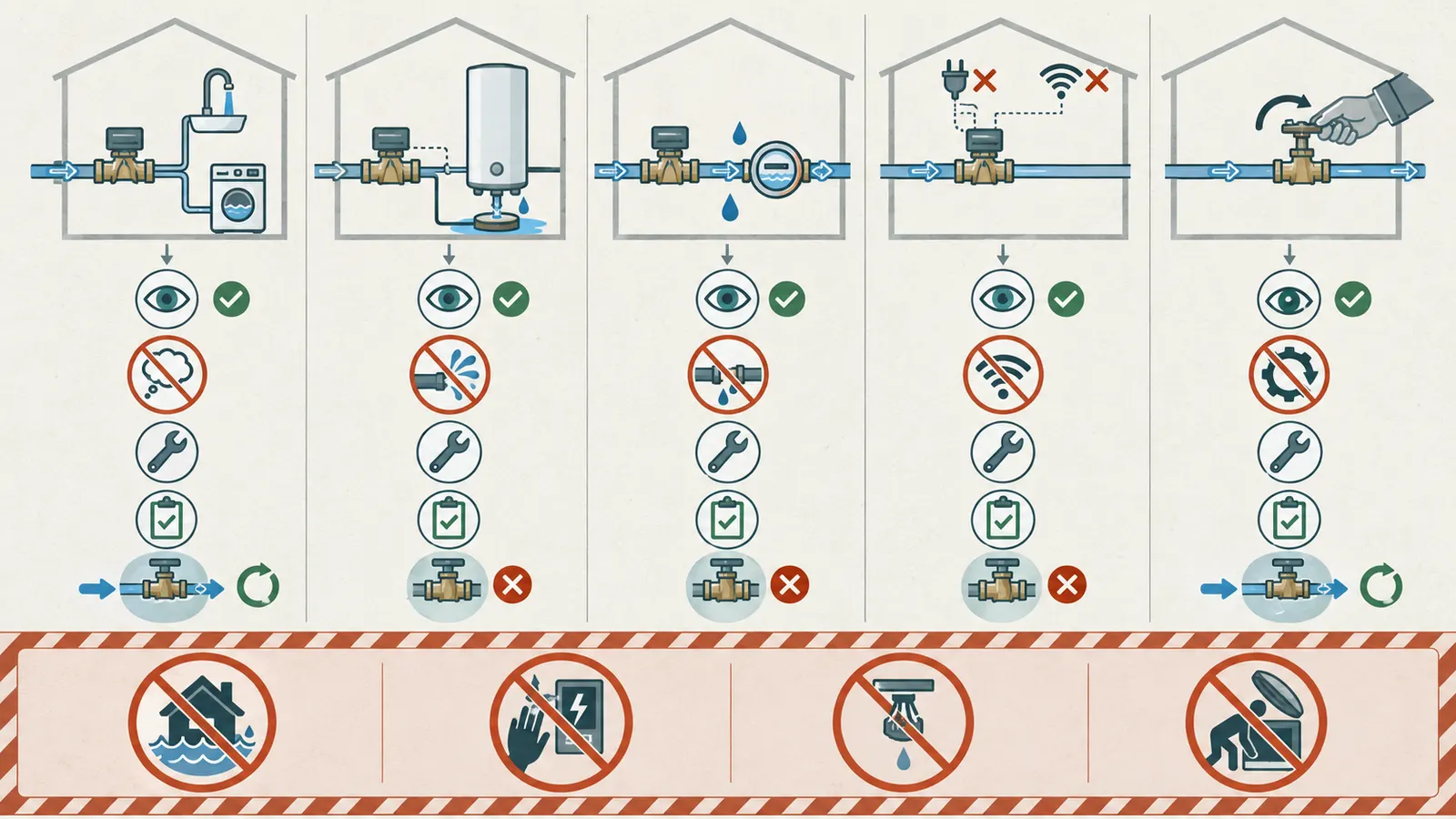
Treat standby, learning, and maintenance modes as unprotected states until proven otherwise
Manufacturers often provide modes to prevent a legitimate large water use from triggering an alert. Watts/Sentinel states that its standby mode allows water to flow without alarming and that water entering the structure is not monitored during standby. Moen describes Home, Away and Sleep modes and warns that Sleep mode ignores proactive and real-time tests and quiets alarm notifications. These examples show why the turnover record must name temporary modes, their purpose, who may use them, how long they last and how they are cleared.
Never write “system active” while a mode intentionally suppresses monitoring. In the worksheet, use a visible state such as “monitoring suspended—restore after contractor use.” The builder should tell every trade how to prevent a temporary setting from becoming permanent. The owner should receive an alert or checklist for restoring ordinary operation after pool filling, commissioning, move-in, treatment service or a high-use event.
Establish maintenance ownership
The system becomes part of home ownership when batteries, sensors, network credentials, app support, valve exercise, calibration and records have owners. The exact schedule comes from the product documents; the planning schedule below is a responsibility framework, not a universal interval.
| Task | Trigger or interval to record | Owner | Evidence |
|---|---|---|---|
| Point-sensor battery check | Exact product instruction; Resideo WHLDT guide recommends testing every 6 months and replacing as needed | Homeowner or service provider | Date, battery state and zone |
| Sensor and cable inspection | At the manufacturer’s stated interval and after an alert | Homeowner, plumber or installer as assigned | Clean/dry/secure note and photo |
| Valve movement or exercise | Exact product maintenance instruction | Installer or homeowner if explicitly permitted | Open/close result and exceptions |
| Network and account review | After router, owner or service changes | Homeowner | Alert test and account owner |
| Pressure or device-limit review | When PRV, service, pump or plumbing changes | Plumber | Pressure record and compatibility review |
| Firmware/app or subscription review | According to manufacturer terms | Homeowner | Version/support record, without storing secrets in the build file |
| As-built map update | Every plumbing reroute or added automatic user | Builder/plumber and homeowner | Revised branch drawing |
| Warranty file | At installation and any replacement | Builder/installer/homeowner | Model, serial, receipt, guide, registration and calibration |
The Resideo WHLDT guide says its cable can be extended up to 240 feet with one alarm and recommends six-month battery testing. That is useful if a point-sensor plan is selected, but it is not a rule for a different cable or hub. Record the exact cable part number and the alarm it serves. A long cable routed through inaccessible framing can make future replacement difficult even if it falls within the published limit; plan a replaceable path and a labeled endpoint.
Complete the worksheet and release the next decision #
The next decision after this article is not “buy the most capable device.” It is “Can the project issue a coordinated, model-specific rough-in scope with no unresolved branch or recovery gate?” Complete the worksheet, obtain the responsible trade responses, then choose the candidate that passes hard gates and best serves the recorded household priorities.
Original contribution: Pre-rough-in branch-topology worksheet and release matrix
This guide’s original contribution is the Pre-rough-in branch-topology worksheet and release matrix. It is designed to be copied into the project decision log and reviewed at three moments: design coordination, pre-concealment inspection and homeowner turnover.
Method. Map the service line, meter, PRV, fire-sprinkler and irrigation branches, treatment equipment, automatic appliances and sensor zones before rough-in. Compare point sensing, whole-home flow monitoring, automatic shutoff and combined architectures against coverage, intervention, access, power, connectivity and recovery inputs. Use the stated manufacturer documents for model-specific limits and release only after the named trade verifies its row.
Limitations. This is an illustrative planning synthesis, not a code approval, hydraulic design, fire-protection determination, electrical design, product ranking, insurance promise, leak diagnosis or measured performance study. Exact model revision, pipe size, pressure, temperature, utility requirements, adopted rules and AHJ decisions must be rechecked for the actual United States project address.
Worksheet A: project decision record
Fill the blanks with the project’s own data. Do not replace an unknown with a guessed value.
| Record field | Project value | Source or owner | Status |
|---|---|---|---|
| Property address and actual AHJ | Homeowner / builder | ||
| Market and service type | U.S.; municipal / private / other: | Homeowner / utility / plumber | |
| Desired outcome | Alert / local alarm / remote alert / automatic close / point confirmation | Homeowner | |
| Definition of “whole home” | Indoor domestic / property water / named branches: | Homeowner and plumber | |
| Service-line size and material | Plumber | ||
| Meter location and utility constraints | Utility / plumber | ||
| Primary manual shutoff | Plumber | ||
| PRV and pressure record | Plumber | ||
| Candidate model and revision | Homeowner / plumber / supplier | ||
| Proposed valve location and envelope | Plumber / designer | ||
| Required pipe length and connections | Exact installation guide / plumber | ||
| Access and removal path | Designer / builder / plumber | ||
| Power requirement and outlet | Exact guide / electrician | ||
| Controller or network location | Exact guide / electrician / owner | ||
| Manual recovery method | Exact owner guide / installer | ||
| Warranty and registration record | Manufacturer / installer | ||
| Account or subscription owner | Homeowner / builder | ||
| Next decision date | Builder schedule |
Worksheet B: branch register
Create one row per branch, including a branch that appears “obvious.” The purpose is to expose the split point and response, not to generate a fixture count.
| Branch ID | Water user or system | Split point relative to valve | State: monitored / excluded / separately sensed / unresolved | Sensor or valve response | Normal automatic use | Responsible trade | Verification record |
|---|---|---|---|---|---|---|---|
| B-01 | Fire sprinklers | Fire-sprinkler designer / plumber | |||||
| B-02 | Irrigation | Irrigation designer / plumber | |||||
| B-03 | Indoor domestic manifold | Plumber | |||||
| B-04 | Water heater | Plumber / HVAC | |||||
| B-05 | Treatment equipment | Plumber | |||||
| B-06 | Kitchen and refrigerator | Plumber / appliance installer | |||||
| B-07 | Laundry | Plumber / appliance installer | |||||
| B-08 | Bathrooms | Plumber | |||||
| B-09 | Hose bibs | Plumber | |||||
| B-10 | Other automatic user: |
For every excluded row, write the reason and alternate protection. “Excluded because it is before the valve” is an observation; it is not a protection plan. Add “no automatic closure,” “separate local shutoff,” “separate sensor,” “fire-protection state,” “irrigation controller,” or another verified response. For every separately sensed row, name the battery or power requirement, sensor cable or zone, alert destination, replacement access and maintenance owner.
Worksheet C: product and trade release matrix
Use one copy per candidate, then keep the selected copy with the as-built record.
| Gate | Candidate requirement | Evidence/document | Owner | Pass / fail / open | Correction and due date |
|---|---|---|---|---|---|
| Branch topology | Marked plumbing plan | Plumber | |||
| Fire-sprinkler relationship | Fire plan, designer/AHJ record | Fire-sprinkler designer / builder | |||
| Irrigation relationship | Civil/irrigation/plumbing plan | Plumber / irrigation designer | |||
| Service-line and pressure fit | Model guide and pressure record | Plumber | |||
| Pipe length and connections | Dimensioned detail | Plumber | |||
| Orientation and flow arrow | Installation guide and field photo | Plumber | |||
| Access and support | Utility-room elevation and photo | Designer / builder / plumber | |||
| Power and environmental condition | Electrical plan and test | Electrician | |||
| Connectivity and local control | Network/control test | Electrician / installer / homeowner | |||
| Manual override | Owner guide and demonstration | Installer / homeowner | |||
| Point-sensor coverage | Zone map and approved test | Installer | |||
| Calibration or learning | Product-specific record | Installer | |||
| Normal water-user test | Event log | Plumber / appliance owner | |||
| Warranty and model revision | Warranty, serial and receipt | Builder / installer | |||
| Handover and maintenance | Packet index and schedule | Builder / homeowner |
Worksheet D: event and recovery log
Use it for commissioning, later maintenance and any unexpected shutoff. It is an owner record, not an official inspection form.
| Date/time | Event or test | Branch/zone | Valve state before/after | Alert/control observed | Safe action taken | Professional contacted | Retest/closeout |
|---|---|---|---|---|---|---|---|
Final release gates and next handoff
Release the architecture to rough-in only when all of these are true:
- the desired response and definition of coverage are written;
- every water branch is mapped relative to the proposed valve;
- no branch is still labeled unresolved;
- fire-sprinkler coordination is recorded for the actual project jurisdiction;
- irrigation and automatic water users have an explicit state;
- the exact device model, revision and instructions are saved;
- pipe length, size, orientation, support and access are confirmed;
- power, controller and network responsibilities are assigned;
- manual recovery is documented and teachable;
- the selected candidate passes hard gates;
- the preference score and sensitivity are recorded as illustrative decision support, not fact;
- the plumber, electrician, builder and applicable fire-sprinkler designer have reviewed their handoffs.
After rough-in, the next decision is whether the as-installed system still matches the approved topology. If it does not, stop at the next concealment gate and reopen the matrix. After commissioning, the next decision is whether the homeowner accepts the system into ownership with the current model, records, maintenance owner, account transfer, manual recovery and unresolved-item list. Continue related planning in the Brictale homeowner blog, keeping the water-control record connected to the broader build journey rather than treating it as a standalone gadget purchase.
Originality brief
- Current answers: EPA explains moisture sensing, flow monitoring, coverage and intervention categories, while Moen, Watts/Sentinel, Resideo and Uponor explain their own products, controls, limits and maintenance prompts.
- Missing decision: A new-home owner still needs to decide which actual water branches are monitored, excluded or separately sensed, whether a valve may safely close the selected branch, and who will reserve, verify and hand over the physical and control provisions before rough-in.
- Original contribution: This page combines those source-scoped constraints into the Pre-rough-in branch-topology worksheet and release matrix, including a branch register, hard gates, an illustrative weighted comparison, sensitivity, responsibility matrix, commissioning log and recovery record.
- How to check it: For each selected row, compare the as-built redline and product revision with the cited manufacturer instruction, obtain the responsible trade’s verification, run the approved commissioning event, record the valve/sensor/control result, and confirm the homeowner can use the documented recovery path.
This is a decision surface, not a product endorsement. It earns its usefulness by making coverage, exclusions, trade responsibility, verification and recovery visible before they become concealed work. The owner’s final selection should be the one that the actual plumbing topology, fire-protection decision, electrical plan, access detail, qualified installation scope and turnover record can all support.
Cite this guide
Brictale. “How to Plan a New-Home Automatic Water Shutoff and Leak-Detection System Before Rough-In.” Published 2026-09-25; updated 2026-09-25.
https://brictale.com/build/materials/plan-new-home-automatic-water-shutoff-leak-detection-before-rough-in · Read the Markdown version
Original contribution: Pre-rough-in branch-topology worksheet and release matrix. A source-derived worksheet that classifies every new-home water branch as monitored, intentionally excluded, or separately sensed, then records plumbing, power, connectivity, manual recovery, trade ownership and commissioning gates.
Sources and scope
Evidence behind this page
- EPA WaterSense distinguishes moisture detection, which detects unexpected dampness at a designated location, from flow monitoring, which measures pipe flow or pressure and detects irregular use or pressure changes; some systems combine technologies.
Leak Detection and Flow Monitoring Devices | US EPA WaterSense
U.S. EPA WaterSense technical fact sheet, July 2023; general residential technology categories, not a product endorsement or performance guarantee.
Accessed · Link to this claim - EPA WaterSense says in-line devices need enough pipe length and easy access, should not interfere with fire sprinkler systems, and applicable subscription requirements should be communicated at homeowner turnover.
WaterSense Labeled Homes Technical Sheet: Leak Detection and Flow Monitoring System | US EPA
U.S. EPA WaterSense labeled-homes technical sheet, July 2023; planning guidance and verification prompts, not a local fire code or permit decision.
Accessed · Link to this claim - The Moen Flo Shutoff is installed in-line on the main cold-water supply, and current installation guide INS11955B specifies continuous 100–240 VAC power within 10 feet.
Flo Shutoff Installation Guide INS11955B | Moen
Moen Flo Shutoff guide INS11955B, February 2024; exact product-family in-line placement and power instructions, not a universal requirement for other devices.
Accessed · Link to this claim - Moen's current Flo Shutoff support page recommends using a plumbing professional because installation requires removing a section of the main water pipe.
Moen's current Flo Shutoff support page; product-family installation recommendation, not a universal licensing or code requirement for other devices.
Accessed · Link to this claim - Moen's current Flo guide INS11955B recommends continuous pressure no higher than 80 psi, directs the installer to orient the device arrow with water flow toward the dwelling, and says to retain the installation spacer for possible future removal.
Flo Shutoff Installation Guide INS11955B | Moen
Moen Flo Shutoff guide INS11955B, product-specific pressure recommendation, orientation and service-recovery instruction.
Accessed · Link to this claim - Moen's current Flo support page says the device uses a 2.4 GHz Wi-Fi connection, supports remote shutoff through the app, and describes Home, Away and Sleep modes; it warns that Sleep mode ignores proactive and real-time tests and quiets alarm notifications.
Flo Smart Water Monitor and Shutoff Frequently Asked Questions | Moen
Moen's current support page for the Flo Shutoff; product-family connectivity, control and mode descriptions, not a guarantee of availability or behavior for another model.
Accessed · Link to this claim - Moen's current Flo Shutoff support page says the device sends alerts about abnormal water usage and potential leaks but cannot determine exactly where a leak is in the house, and recommends contacting a local plumber if the source cannot be found.
Flo Smart Water Monitor and Shutoff Frequently Asked Questions | Moen
Moen's current support page for the Flo Shutoff; product-family description of alert and location limits, not a universal limitation for every flow-monitoring product.
Accessed · Link to this claim - Moen installation guide INS11955B says an energized Flo device without an internet connection enters local mode and may experience frequent water interruptions until connected to the internet; it requires a weather-resistant enclosure at least 12 inches above grade for outdoor installation.
Flo Shutoff Installation Guide INS11955B | Moen
Moen Flo Shutoff installation guide INS11955B, February 2024; model/revision-specific local-mode and outdoor-placement instructions, not a universal electrical or building requirement.
Accessed · Link to this claim - The Watts/Sentinel Leak Defense System pre-installation survey calls out reverse osmosis, water softeners, irrigation, automatic pool fill, outside hose bibs, booster pumps and other automatic water users as downstream items that may require accessories or a different installation position; it requires the valve downstream of fire-sprinkler and irrigation branches in the described layout.
Watts/Sentinel Leak Defense System manual dated 2022-09-14; named system and depicted piping configurations, not a national plumbing or fire rule.
Accessed · Link to this claim - The Watts/Sentinel Leak Defense System manual describes placing its valve downstream of a primary manual shutoff and pressure regulator, notes that some utilities require at least 18 inches downstream of the utility meter, says a bypass may be recommended, and warns that a layout differing from the diagram needs system-specific recommendations.
Watts/Sentinel Leak Defense System manual dated 2022-09-14; product and utility-scope installation prompts, not a national meter-clearance, bypass or plumbing-code requirement.
Accessed · Link to this claim - The Watts/Sentinel manual describes its local wireless control panel as a place to turn water on or off, change Home, Away and Standby scenes, set trip-rate and time-to-alarm values, and check system status; it specifies the panel within 100 feet of the valve and recommends 50 feet or less for reliable connection.
Watts/Sentinel Leak Defense System manual dated 2022-09-14; exact panel functions and placement guidance for that system.
Accessed · Link to this claim - The Watts/Sentinel manual specifies a dry, non-switched 120 VAC outlet for the valve transformer, a maximum 100-foot 24 VAC run, a control panel within 100 feet of the valve with 50 feet or less recommended for reliable connection, and an outlet within 6 feet of the panel.
Watts/Sentinel Leak Defense System manual dated 2022-09-14; exact power and control-panel planning values for that system.
Accessed · Link to this claim - The Watts/Sentinel manual warns that power should be disconnected before manual valve operation and describes a manual override for systems 1.5 inches or smaller and a different knob procedure for systems 2 inches or larger.
Watts/Sentinel Leak Defense System manual dated 2022-09-14; model-size-specific manual recovery instruction.
Accessed · Link to this claim - The Watts/Sentinel manual directs the installer to confirm the actuator closes and reopens, verify the control-panel shutoff feature, calibrate the system, and record calibration values for warranty validation; it states that standby means water entering the structure is not monitored.
Watts/Sentinel Leak Defense System manual dated 2022-09-14; commissioning and operating-mode instructions for that product.
Accessed · Link to this claim - The Watts/Sentinel Leak Defense System manual warns that bracing may be required when the plumbing cannot support the system weight and recommends a battery backup or generator for locations prone to power outages.
Watts/Sentinel Leak Defense System manual dated 2022-09-14; named-system installation warning and recommendation, not a universal structural or backup-power requirement.
Accessed · Link to this claim - EPA WaterSense advises understanding manufacturer limitations such as higher-water-pressure conditions or compatibility with certain meter models, and selecting a device capable of monitoring all water use intended for the home, including indoor and outdoor use when applicable.
WaterSense Labeled Homes Technical Sheet: Leak Detection and Flow Monitoring System | US EPA
U.S. EPA WaterSense technical fact sheet, July 2023; general product-selection guidance, not a product-specific pressure rating, meter approval or local code decision.
Accessed · Link to this claim - Resideo's current L5 installation instructions 33-00607EFS—08 list the VWS01Y-1 as a 1-inch NPT ball-valve variant and describe app control, manual or emergency-handle control, any-orientation installation, a 10-foot power adapter and a 100–240 V adapter input.
33-00607EFS—08 L5 WiFi Water Leak Shutoff Valve Installation Instructions | Resideo
Resideo/First Alert L5 installation instructions 33-00607EFS—08, revision December 2025; exact named VWS01Y-1 variant and listed control/power/placement features, not a claim that every L5 variant has the same dimensions or limits.
Accessed · Link to this claim - Resideo's current L5 installation instructions 33-00607EFS—08 state that the product is designed for indoor use and must not be installed on fire sprinkler or suppression systems because doing so may prevent operation in an emergency.
33-00607EFS—08 L5 WiFi Water Leak Shutoff Valve Installation Instructions | Resideo
Resideo/First Alert L5 installation instructions 33-00607EFS—08, revision December 2025; named product safety and placement instructions, not a substitute for the actual fire-protection designer or AHJ.
Accessed · Link to this claim - The Resideo Water Leak Alert WHLDT guide places a detector or cable where leaks are likely, allows cable extension up to 240 feet with one alarm, and recommends testing batteries every six months and replacing them as needed.
34-00023EFS-07 Water Leak Alert Owner's Guide | Resideo
Resideo WHLDT point/cable sensing product guide; exact detector and cable instructions, not whole-home flow monitoring.
Accessed · Link to this claim - Uponor's Phyn Plus product page describes a single supply-line device that monitors the home's water system, includes automatic shutoff, sends notifications, offers remote shutoff, performs daily pressure and tiny-leak checks, and can provide usage insights by fixture categories.
Uponor and Phyn Plus Smart Water Leak Detector | Uponor
Uponor product page for Phyn Plus; manufacturer-described capabilities and marketing scope, not independent performance testing or a guarantee of leak location.
Accessed · Link to this claim