How to Compare New-Home Heating Energy Paths Before Design Freeze
Compare heat pumps, electric backup, dual-fuel and gas furnace systems using load, design temperature, service, fuel, controls, cost and verification records.
The short answer
Carry four complete paths into design development: an all-electric heat pump, heat pump with electric backup, dual-fuel heat pump and furnace, and furnace with separate cooling. Compare each against the same Manual J or equivalent load, design temperature, low-temperature capacity, service and fuel prerequisites, controls, modeled delivered-heat cost, resilience needs, refrigerant compliance, matched-system record and warranty. Choose only after the HVAC designer and other responsible professionals sign off on the handoff record.How to Compare New-Home Heating Energy Paths Before Design Freeze
For a new U.S. single-family home, compare an all-electric heat pump, heat pump with electric backup, dual-fuel heat pump and furnace, and furnace with separate cooling against the same calculated load and design temperature. Record low-temperature capacity, service and fuel prerequisites, controls, delivered-heat cost, resilience, compliance, matched equipment and warranty. Choose only after responsible local professionals verify the handoff.
Freeze the decision only after four records agree #
The heating path is ready for design freeze only when the load record, equipment record, site-services record and responsibility record tell the same story. A fuel preference or an attractive equipment efficiency number is not enough, because the choice changes the electrical service, fuel infrastructure, cooling system, equipment-room layout, controls, budget, maintenance plan and future repair options at the same time.
This guide is scoped to a new single-family home in the United States before design development is frozen. “United States” is the market scope, not a claim that one code, incentive, utility tariff or installation practice applies in every state, county, city or tribal jurisdiction. The authority having jurisdiction (AHJ) for the project decides which adopted building, mechanical, electrical, energy, fuel-gas and fire requirements apply. Your HVAC designer and other licensed or otherwise qualified local professionals must identify that AHJ and verify the current rules; a remote article cannot determine whether a particular system is permitted at your address.
The four paths in this comparison are:
| Path | Primary heat | Backup or second heat source | Cooling implication | Main prerequisite to expose |
|---|---|---|---|---|
| All-electric heat pump | Air-source heat pump | None, or a deliberately limited resilience plan | The heat pump can provide heating and cooling | Adequate low-temperature capacity and electrical service |
| Heat pump plus electric backup | Air-source heat pump | Electric resistance elements in the air handler, or another electric supplemental source | One heat-pump cooling path | Service capacity, backup staging and protection from expensive strip-heat operation |
| Dual fuel | Air-source heat pump | Natural-gas or propane furnace | Shared duct system can provide cooling through the heat-pump coil or separate cooling equipment | Fuel availability, combustion venting, controls and the switchover decision |
| Furnace plus separate cooling | Gas or propane furnace | Usually no second heat source | Separate air conditioner or other cooling system | Combustion equipment, venting, fuel delivery and a separately matched cooling system |
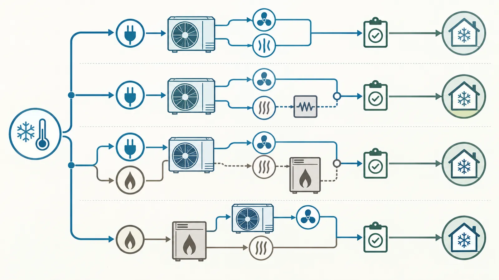
The first three rows are not three appliance purchases with interchangeable labels. An all-electric heat pump may be designed to meet nearly all of the design load, or it may be paired with resistance heat as a capacity and resilience decision. “Dual fuel” normally means a heat pump and combustion furnace share distribution and controls, but the exact arrangement must be shown in the equipment schedule. A furnace with separate cooling is a combustion-first path; do not count the air conditioner as a heating backup.
The original contribution: a checkable comparison record
The original contribution in this article is the Heating-path design-freeze worksheet and decision matrix. Existing explanations often compare heat pumps and furnaces at the appliance level. This record compares the entire energy path at the moment when a homeowner can still change the floor plan, service size, utility coordination, equipment room, duct design and contract scope without a costly redesign.
Method. Record one common load and design condition, transcribe delivered capacity and input from each candidate's published data at that condition, calculate capacity gap and modeled delivered-heat cost, score non-price constraints, then test the result against colder design temperatures, rate changes and backup hours.
Limitations. The worksheet is an illustrative planning synthesis, not an engineering design, code interpretation, utility quote or field test. Rates, incentives, equipment availability, installation quality, maintenance, warranty terms and AHJ requirements are local and time-sensitive; a qualified HVAC designer, electrical professional, builder and serving utilities must verify the final package.
Originality brief. Current answers explain heat pumps, furnaces and dual fuel as technologies, often for replacement shopping. The missing decision is the new-home design-freeze handoff where load, low-temperature capacity, service, fuel, controls, cooling, compliance, warranty and responsibility must agree at once. This worksheet is the contribution: it can be checked by tracing each filled cell to a load calculation, exact manufacturer record, AHRI record, utility or fuel document, tariff, control sequence or named professional, then rerunning the formulas and sensitivity rows when an input changes.
The four records to request
Ask the project team to produce these records before you choose a path:
- Load record: room or block heating load in Btu/h, cooling load in Btu/h, indoor design condition, outdoor heating design temperature, cooling design condition, assumptions for insulation, windows, infiltration, ventilation, duct location and internal gains.
- Equipment record: manufacturer, model numbers, indoor and outdoor units, coil or air-handler pairing, delivered capacity at the heating design temperature, capacity at a colder point, power input or COP, minimum and maximum capacity, auxiliary-heat stages, controls, refrigerant, clearances and warranty conditions.
- Site-services record: available electric service and calculated demand, proposed circuit and disconnect, gas or propane availability and pressure, meter or tank location, venting route, condensate disposal, outdoor-unit location, noise or snow exposure, and any utility or AHJ coordination.
- Responsibility record: the named HVAC designer, electrical professional, builder, fuel contractor, equipment installer, controls commissioner and homeowner representative, with the document each person must approve and the date of the next handoff.
If one option cannot fill a field, it is not yet comparable. “36,000 Btu heat pump” without the outdoor temperature, indoor match and delivered capacity is a nominal label, not a design input. “97% efficient furnace” without output capacity, AFUE context, venting, fuel type and duct losses is also incomplete.
The next decision after this chapter is whether the home has enough defined information to request comparable proposals. If not, carry the unresolved field as a design action with an owner and due date. Continue the broader project sequence in Brictale's design planning route and budgeting route, but keep this article's worksheet as the system-level decision record.
Convert the home into comparable heating inputs #
Use the same load and design condition for every candidate; otherwise a larger furnace will appear more reliable simply because it was compared with a smaller heat pump under different assumptions. A Manual J or equivalent load calculation is the common input, while equipment selection and controls are later professional decisions.
The DOE-hosted Guide To Sizing & Selecting Air-Source Heat Pumps in Cold Climates directs readers to ACCA Manual J or equivalent load calculations for new construction and to manufacturer-published performance at design conditions for selecting adequate heating and cooling capacity. Read the DOE-hosted sizing guide before accepting a proposal that shows only nominal tonnage or furnace input. That source is cold-climate guidance; it is not a universal code rule and does not tell a designer what your home's load is.
Step 1: establish the jurisdiction and design conditions
Write the project location as a complete address or parcel description, then ask the HVAC designer which weather data and design-temperature convention they used. Record:
- jurisdiction: state, county, city or other AHJ as applicable;
- indoor heating design temperature and cooling design temperature;
- outdoor heating design temperature in °F;
- outdoor cooling dry-bulb and, where relevant, humidity or wet-bulb condition;
- elevation and unusual exposure, such as wind, shade, coastal air or snow;
- whether the calculation is room-by-room, block load, or both;
- ventilation or infiltration assumptions, including whether an energy-recovery ventilator is part of the design;
- construction assumptions that are still provisional, such as window U-factor, solar heat gain coefficient, insulation levels and air-sealing target.
Do not replace the designer's design temperature with the lowest temperature you remember from a weather app. A design temperature is a planning condition, not a prediction that the weather will never be colder. If the actual cold snap is below the design condition, the system's backup, capacity reserve, controls and building envelope determine how the home responds.
Ask for the design temperature in °F and the source or method used. If the team uses °C, keep the original units and add the conversion rather than silently mixing numbers. The conversion is:
°F = (°C × 9/5) + 32
For example, a modeled outdoor design temperature of −18°C is −0.0°F after conversion? No: calculate it explicitly: (−18 × 9/5) + 32 = −0.4°F, which rounds to approximately 0°F. This is a unit conversion example, not a claim about any location's official design temperature.
Step 2: obtain the heat-loss and cooling-load inputs
Request a table, not just a total. At minimum, the table should show each zone or the block total, floor area, design heating load, design cooling load and the assumptions that produce them. A useful record distinguishes transmission through walls, roofs, floors, windows and doors from infiltration, ventilation and other loads. The goal is not for the homeowner to audit Manual J line by line; the goal is to catch a proposal that selects equipment from square footage alone.
Record these values:
| Input | Unit | Why it changes the choice | Who supplies or verifies it |
|---|---|---|---|
| Total design heating load | Btu/h | Sets required delivered heat at the chosen outdoor condition | HVAC designer |
| Design cooling load | Btu/h | Constrains cooling size, dehumidification and equipment pairing | HVAC designer |
| Room or zone loads | Btu/h | Tests distribution and comfort, not just the central machine | HVAC designer |
| Heating design temperature | °F | Sets the comparison point for heat-pump capacity | HVAC designer using project weather method |
| Indoor design setpoint | °F | Defines the temperature difference the load serves | Homeowner and designer |
| Ventilation and infiltration assumption | cfm or stated method | Changes load and may affect indoor air quality equipment | HVAC designer and energy designer |
| Duct location and insulation | location, R-value | Changes delivered performance and moisture/comfort risk | Designer and builder |
| Electrical service and calculated demand | A, V, phase, kW or kVA | Determines whether resistance backup or electrification fits | Electrical professional and utility |
| Fuel availability | natural gas, propane, none | Determines whether combustion path is physically available | Utility, fuel supplier and contractor |
If the design is very efficient and the load is small, oversizing is still a risk. A large furnace may short-cycle; a large heat pump may have a minimum capacity that exceeds the cooling load; a multi-zone outdoor unit may not turn down enough. The DOE sizing guide specifically warns in its new-construction guidance to avoid oversizing and to look at minimum-speed capacity and turn-down behavior. Use the guide's new-construction sizing notes as a question list, not as a substitute for equipment selection.
Step 3: separate input capacity from delivered capacity
For a furnace, record both fuel input and rated output if the manufacturer publishes both. AFUE is seasonal and does not tell you that a furnace can deliver a particular output at every operating condition. For a heat pump, record the delivered heating capacity at the outdoor design temperature, the electrical input at that point, the control mode used for that rating and whether supplemental heat is included or excluded.
For cooling, record the matched system's rated cooling capacity and minimum capacity. A heat pump can provide both space heating and cooling, and DOE notes that local climate matters because outdoor air is the heat source and heat sink. See DOE's residential air-source heat-pump guidance. That shared cooling path is a benefit, but it also means a heat-pump decision must work as a cooling and dehumidification decision.
For a gas or propane furnace, ask whether the planned combustion appliance is condensing or non-condensing, where it will draw combustion air, where it will vent, how condensate will be handled if applicable, and what the actual input and output are. Do not infer the venting method from a product photograph.
Step 4: define the distribution system before scoring comfort
The heating source and the way heat reaches rooms are separate decisions. A ducted heat pump, a ducted furnace, a compact-ducted system and a ductless system do not create the same air movement, thermostat placement, filtration, sound, visual impact or backup options. For this approved opportunity, the comparison can include ductless equipment only if it is a genuine whole-home design candidate, but do not let a room-by-room ductless quote evade the block-load question.
Ask for supply and return locations, room airflow targets, duct dimensions, filter size and pressure assumptions. If ducts are in an attic, crawlspace or garage, ask how the designer accounted for their location. DOE guidance warns that leaky ducts and improper installation can reduce efficiency and comfort, so a high equipment rating cannot rescue an undefined distribution system. Review DOE's installation and maintenance cautions.
The next handoff is a common input sheet signed or acknowledged by the homeowner, HVAC designer and builder. Only after all four candidates use that same sheet should you begin operating-cost comparison.
Compare four paths as complete systems #
An apples-to-apples heating comparison asks what each path must contain, what it can do at the design condition, what happens below that condition, and which separate system costs or risks it creates. The preferred row is not the one with the highest seasonal label; it is the one that satisfies the home's load and constraints with a controllable, serviceable and documented system.
Path A: all-electric heat pump
An all-electric heat pump moves heat from outdoor air into the home in heating mode and reverses that process for cooling. It avoids on-site combustion fuel storage or gas piping, but it still needs electrical capacity, a suitable outdoor location, condensate and defrost management, refrigerant piping, controls, service access and a plan for unusual cold or outage conditions.
Ask the designer:
- What is the delivered heat-pump capacity at the heating design temperature?
- What percentage of the calculated heating load does that capacity cover?
- At what outdoor temperature does the heat-pump capacity equal the building load—the modeled balance point?
- What happens below the balance point: indoor temperature drift, staged resistance heat, reduced setpoint, another source, or a resilience plan?
- Is the proposed unit certified for the intended climate, and does the exact indoor/outdoor combination have a current performance record?
- What electrical demand does the compressor, outdoor fan, indoor blower and any crankcase or supplemental heater create at design and extreme conditions?
- How will the system operate during defrost, and how will the homeowner know whether backup heat is running?
ENERGY STAR's February 2026 criteria are useful evidence for screening cold-climate candidates: a residential heat pump with the Cold Climate designation must demonstrate a COP of at least 1.75 at 5°F, at least 70% of its 47°F heating capacity at 5°F, and native-controls verification at the low-ambient test point. Read the current ENERGY STAR Version 6.2 criteria. These are certification test requirements, not a promise that your home will receive that capacity at a different temperature, voltage, airflow, duct condition or installation quality.
The advantage of the all-electric row is system consolidation: one compressor-based system can supply both heating and cooling, and the home does not depend on fuel delivery for normal operation. The tradeoff is that the electrical service and backup strategy are part of the heating design, not an afterthought. If the home is in an outage-prone area, “all electric” does not itself mean resilient; it means the resilience plan must address the heat pump and any electric backup.
Path B: heat pump with electric resistance backup
This path uses the heat pump for ordinary heating and electric resistance elements when the heat pump cannot meet the load, during defrost, or when controls decide that recovery needs supplemental heat. The resistance elements are simple in principle but can add substantial electrical demand. The designer must show their staged capacity, breaker and conductor requirements, service impact, control lockouts and expected annual hours.
Do not compare the resistance elements as though they were the heat pump. A heat-pump COP is a ratio of delivered heat to electrical input at a test condition; ENERGY STAR defines it that way. See ENERGY STAR's COP definition. Electric resistance heat has a modeled site COP of approximately 1 when one unit of electrical energy becomes one unit of heat at the element, before distribution losses; label this as a modeling convention and ask the designer to use the applicable equipment data. A heat pump with a COP of 2.5 at the same condition would deliver 2.5 times as much heat per unit of input energy under that simplified comparison.
The useful questions are not “Does it have backup heat?” but:
- How many kW of resistance heat are installed, and in what stages?
- What is the maximum combined demand when the heat pump and resistance elements run together?
- Does the thermostat prevent resistance heat during normal recovery or limit it by outdoor temperature, load, or time?
- What is the modeled number of backup hours for the design winter, and what happens in a colder-than-design event?
- Can one stage maintain essential rooms if the service or generator plan is constrained?
- Are the air handler, heat strips, breakers, disconnects and service conductors included in the proposal?
DOE's purchasing guidance says residential heat pumps are often selected based on cooling capacity and electric resistance is added to make up heating deficiencies; it recommends minimizing resistance use and using a heat-pump-specific thermostat that ramps temperature changes to avoid unnecessary resistance operation. Review DOE's heat-pump selection and use guidance. This is why a cooling-size proposal with a vague “10 kW heat kit” is not a completed heating path.
This row can be a sensible choice when the electrical service has capacity, fuel infrastructure is undesirable or unavailable, the heat pump has strong low-temperature performance, and the homeowner accepts the cost and demand consequences of occasional resistance operation. It becomes a weak choice when the project has a constrained service, high winter electric rates, frequent outages without backup power, or a control plan that silently uses strip heat for ordinary thermostat recovery.
Path C: dual-fuel heat pump and furnace
Dual fuel combines an air-source heat pump with a gas or propane furnace. The heat pump usually handles milder conditions, while the furnace supplies heat below a selected switchover or balance condition, but exact control behavior varies. The two appliances may share ducts while using different heat sources and safety interlocks.
Ask for a written control sequence, including:
- outdoor temperature at which the system switches;
- whether heat-pump and furnace operation are mutually exclusive or can overlap;
- how the system handles defrost;
- what happens when the outdoor sensor fails;
- whether fuel price is part of the switchover logic or the temperature is fixed;
- what the homeowner sees on the thermostat;
- what happens after a power interruption, fuel interruption or furnace lockout;
- who can diagnose a problem when the heat pump works but the furnace does not, or vice versa.
The switchover temperature is not a universal number. It depends on the building load, heat-pump capacity and COP at the outdoor condition, furnace output and AFUE, electric and fuel rates, demand charges where applicable, comfort goals, emissions goals and the controls' permitted range. A low switchover may use more electricity but less gas; a high switchover may protect heat-pump capacity or reduce electric cost while increasing combustion operation. Model it rather than borrowing a thermostat default.
The advantage is optionality: the heat pump can handle much of the season and cooling, while the furnace can provide high delivered output in cold weather or when the homeowner wants to avoid resistance heat. The tradeoffs are two heat-producing appliances, more controls, combustion venting, fuel infrastructure, two service specialties and a greater chance that a scope gap leaves one mode uncommissioned.
If combustion equipment is located inside the conditioned space, ask the designer about sealed direct vent. DOE Building Science Education explains that direct-vent appliances bring combustion air from outdoors and exhaust byproducts through a separate sealed pipe; it identifies backdrafting as combustion products being drawn indoors by negative pressure and describes sealed direct vent as the safest usual choice for such conditioned-space installations. Read DOE's direct-vent explanation. This does not decide which appliance is legal in your jurisdiction, and it does not authorize homeowner installation.
Path D: combustion furnace with separate cooling
This is a furnace-first system with an independent cooling system, often a central air conditioner, though the final design may use another cooling method. Compare it as two systems with shared distribution only if the documents prove the match. A furnace's AFUE measures seasonal fuel conversion, but it does not include every fan, control, duct or standby cost. See ENERGY STAR's furnace criteria and AFUE explanation.
ENERGY STAR's current furnace criteria list residential gas-furnace certification thresholds of at least 97% AFUE in its U.S. North region and at least 95% AFUE in its U.S. South region, with state groupings shown on the criteria page. Those are ENERGY STAR certification thresholds, not a national code rule. Check the exact ENERGY STAR furnace criteria and regional list. Do not label a furnace “North” or “South” based on climate intuition; use the source's listed state grouping and the product's current record.
The combustion-first row may be attractive where gas or propane is already available, the service is constrained, the local HVAC team is stronger at furnace systems, or the homeowner values high cold-weather output from a stored or delivered fuel. It carries obligations: fuel availability and price, venting, combustion air, condensate for condensing units, carbon-monoxide protection, maintenance, supply-chain support and possible future restrictions or equipment changes. The separate cooling system also needs its own capacity, efficiency, refrigerant, match, condensate and service record.
Do not use “reliable” as a substitute for a resilience definition. A furnace still needs electricity for controls and blower operation. A propane tank still needs delivery. A gas meter still depends on the serving system. A separate air conditioner does not heat the home. Write down the actual outage scenario you care about and ask the team to model it.
A first-pass decision matrix
Use this matrix to expose a path that deserves more design work. It is not a universal ranking. Mark each cell pass, conditional, or fail, then attach the evidence or unresolved action.
| Criterion | All-electric heat pump | Heat pump + electric backup | Dual fuel | Furnace + separate cooling |
|---|---|---|---|---|
| Covers load at design temperature | Capacity record required | Heat pump plus staged backup record | Heat pump and furnace capacity records | Furnace output record |
| Colder-than-design strategy | Explicit resilience plan | Strip-heat hours and demand plan | Furnace switchover and fuel plan | Furnace capacity and fuel continuity |
| Electrical service fit | Compressor, blower and controls | Add resistance kW and staging | Compressor, blower and controls | Furnace blower, controls and cooling |
| Fuel infrastructure | None for space heat | None for space heat | Gas or propane plus venting | Gas or propane plus venting |
| Cooling integration | Same heat-pump system | Same heat-pump system | Usually same distribution; verify match | Separate cooling design |
| Combustion and CO exposure | No on-site combustion | No on-site combustion | Yes, if furnace is gas/propane | Yes |
| Control complexity | Heat-pump controls | Heat-pump and resistance staging | Heat-pump/furnace switchover | Separate furnace/cooling controls |
| Service specialties | HVAC and electrical | HVAC and electrical | HVAC, electrical and fuel | HVAC, electrical and fuel |
| Refrigerant transition check | Required | Required | Required for heat-pump side | Required for separate cooling |
| Best next question | What happens below balance point? | How many backup hours and kW? | What sets switchover and who commissions it? | What are fuel, venting and cooling scopes? |
The next decision is to remove any candidate that fails a hard prerequisite—such as unavailable fuel, inadequate service with no approved upgrade, an unverified capacity at design temperature, or an equipment pairing the manufacturer will not support. Do not eliminate a path merely because its national average cost looks higher or lower; cost is modeled in the next chapter.
Model operating cost and sensitivity without pretending to know your bill #
Compare delivered-heat cost with local rates and explicit performance inputs, then test the result against the assumptions most likely to change. A national average or a single seasonal efficiency label cannot tell you whether a specific new home will have lower annual bills.
DOE's own residential heat-pump examples make this limitation visible: the examples use assumed electricity prices and operating-hour assumptions, state that actual energy savings vary with usage, and direct users to a residential heating-and-cooling cost calculator. Review DOE's stated cost assumptions. Use that as a discipline for your worksheet: every cost result must show its rate, units, hours or heat demand, efficiency assumption and scope.
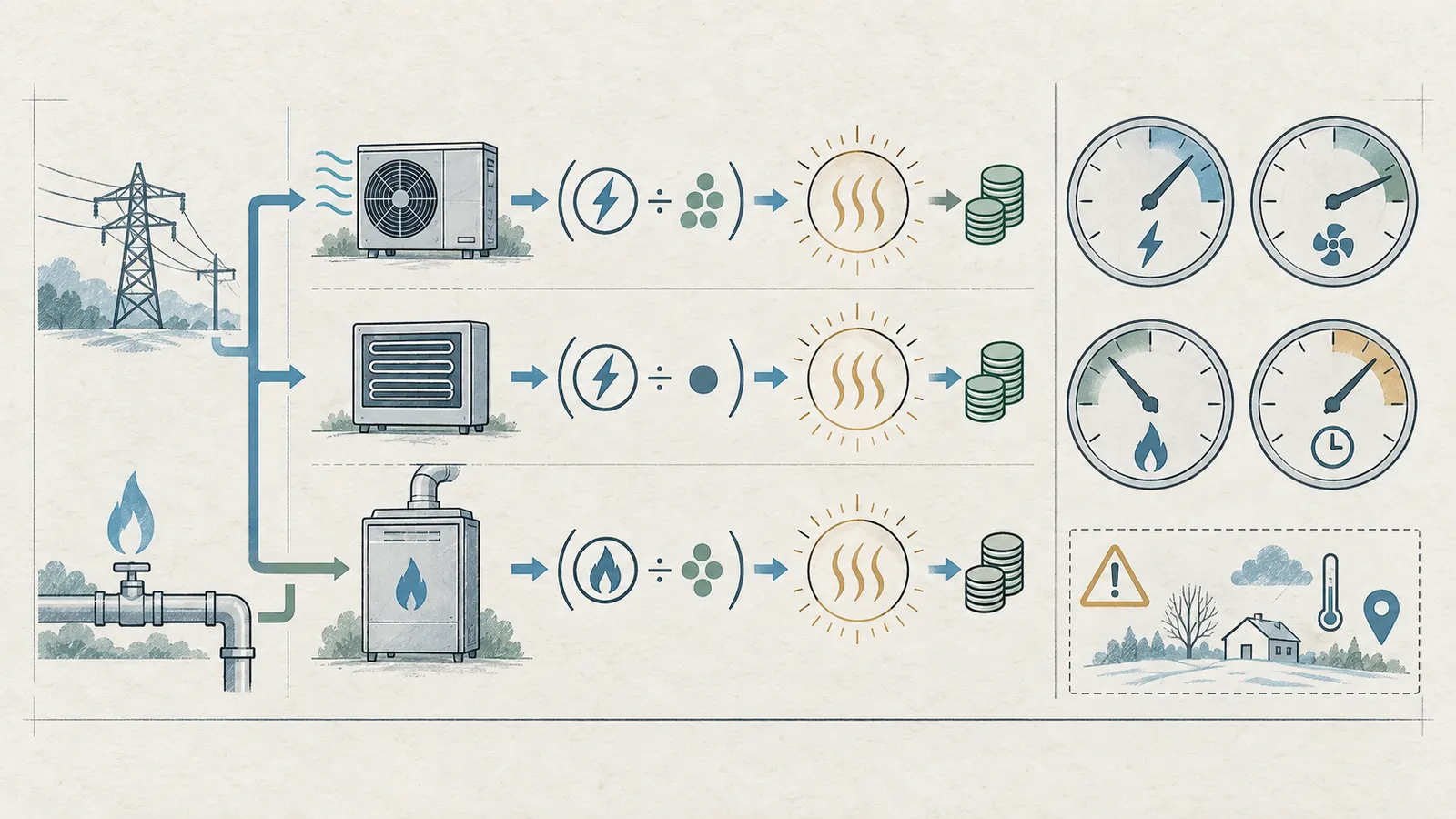
The basic delivered-heat formulas
Use a consistent heat unit. A convenient planning unit is one million Btu delivered to the conditioned space.
Electric heat pump at a point condition
If the load or modeled heat delivered is Q_delivered in Btu and the point-condition COP is COP:
electric kWh = Q_delivered ÷ (COP × 3,412 Btu/kWh)
cost = electric kWh × electric rate ($/kWh)
For 1,000,000 Btu delivered at COP 2.5 and an illustrative rate of $0.18/kWh:
kWh = 1,000,000 ÷ (2.5 × 3,412) = 117.2 kWh
cost = 117.2 × $0.18 = $21.10
This is an illustrative point-condition calculation, not a seasonal bill. It excludes distribution losses, defrost effects, crankcase heaters, fan energy, demand charges, taxes and the fact that COP changes with outdoor temperature and operating mode.
Electric resistance backup
For an illustrative resistance COP of 1.0:
kWh = Q_delivered ÷ (1.0 × 3,412)
cost at $0.18/kWh = 1,000,000 ÷ 3,412 × $0.18 = $52.75
The comparison shows why a small number of resistance hours can materially affect a winter bill, but it does not show when the strips will run. That requires the load, heat-pump capacity curve, control sequence, weather bin or hourly model and installation assumptions.
Gas or propane furnace
If fuel energy is measured in therms, and one therm is modeled as 100,000 Btu input, with furnace AFUE η:
fuel therms = Q_delivered ÷ (100,000 Btu/therm × η)
cost = fuel therms × fuel rate ($/therm)
For 1,000,000 Btu delivered, an illustrative 95% AFUE furnace and $1.20/therm:
therms = 1,000,000 ÷ (100,000 × 0.95) = 10.53 therms
cost = 10.53 × $1.20 = $12.63
Add electricity for the furnace blower and controls if you are comparing whole-system operating cost. If the fuel is propane, use the supplier's billing unit and energy content convention; do not substitute a natural-gas therm price. If the utility charges a fixed customer fee that changes when gas service is added, model that separately from delivered heat.
Dual fuel
For dual fuel, split the annual heat demand into heat delivered by the heat pump above the switchover temperature and heat delivered by the furnace below it. Then calculate each portion with its own performance and rate:
annual operating cost = heat-pump portion cost + furnace portion cost + blower/control cost + fixed fuel-service cost
The split cannot be calculated honestly from the switchover temperature alone. A heat pump may operate at part load for many hours above the switchover; the building load, weather distribution, balance point and controls determine the actual portion. If the controls switch on outdoor temperature but the furnace also stages on indoor temperature, document both rules.
The worksheet's cost-input table
Enter the project's actual values or mark them as unknown. Do not enter a national average just to complete a row.
| Cost input | Value | Unit | Source or assumption | Verified by |
|---|---|---|---|---|
| Annual space-heat demand used in model | million Btu delivered | Load or energy model; state whether site or source energy | HVAC/energy designer | |
| Electricity volumetric rate | $/kWh | Serving utility tariff and applicable rider | Homeowner/utility | |
| Electricity fixed or demand charge | $/month or $/kW | Tariff, if applicable | Homeowner/utility | |
| Natural-gas rate | $/therm | Serving utility tariff | Homeowner/utility | |
| Propane rate | $/gal or other unit | Supplier quote or bounded scenario | Homeowner/supplier | |
| Heat-pump COP or input | COP, kW or Btu/h | Exact model data at multiple outdoor temperatures | HVAC designer | |
| Resistance-backup hours | h/year | Modeled or sensitivity range | HVAC designer | |
| Furnace AFUE and blower input | %, kW | Exact model documents | HVAC designer | |
| Switchover temperature | °F | Control sequence and modeled logic | HVAC designer | |
| Maintenance and service allowance | $/year or scenario | Local service scope, not a generic average | Homeowner/team |
Sensitivity 1: change the electricity rate
Using the illustrative 1,000,000 Btu and COP 2.5 example, the cost is approximately:
| Electricity rate | Heat-pump cost per 1,000,000 Btu at COP 2.5 | Resistance cost per 1,000,000 Btu at COP 1.0 |
|---|---|---|
| $0.12/kWh | $14.06 | $35.17 |
| $0.18/kWh | $21.10 | $52.75 |
| $0.30/kWh | $35.17 | $87.92 |
These figures are modeled examples, rounded, and exclude fixed charges and distribution losses. The point is not to predict a bill; it is to see whether a path's conclusion changes when the rate moves. If a dual-fuel conclusion depends on a small difference between $0.18 and $0.20/kWh, treat it as conditional and ask for a better local tariff analysis.
Sensitivity 2: change COP with outdoor temperature
For the same illustrative 1,000,000 Btu and $0.18/kWh:
| Point COP | Heat-pump kWh | Modeled cost |
|---|---|---|
| 3.0 | 97.7 | $17.58 |
| 2.5 | 117.2 | $21.10 |
| 2.0 | 146.5 | $26.38 |
| 1.75 | 167.5 | $30.15 |
| 1.0 resistance | 293.1 | $52.75 |
ENERGY STAR's cold-climate criterion uses COP at 5°F as one screening point, but your designer must use the candidate's exact extended performance data and the project's actual design conditions. A 5°F COP cannot be assumed at 0°F, 17°F or 35°F. Conversely, a 5°F test result does not prove the exact indoor match, duct airflow, defrost behavior or control sequence at your site.
Sensitivity 3: change backup hours
Suppose a modeled home needs 20,000,000 Btu of seasonal space heat and the all-electric heat pump supplies 95% of it at an average modeled COP of 2.5. The remaining 5% is 1,000,000 Btu supplied by resistance heat. At $0.18/kWh, the illustrative costs are:
heat-pump portion = 19,000,000 ÷ (2.5 × 3,412) × $0.18 = $400.94
resistance portion = 1,000,000 ÷ (1.0 × 3,412) × $0.18 = $52.75
modeled heat cost = $453.69
If backup rises to 15%, then 3,000,000 Btu uses resistance and 17,000,000 Btu uses the heat pump:
heat-pump portion = 17,000,000 ÷ (2.5 × 3,412) × $0.18 = $358.73
resistance portion = 3,000,000 ÷ (1.0 × 3,412) × $0.18 = $158.26
modeled heat cost = $517.00
The difference is about $63.31 in this deliberately simplified scenario. Real results may differ because the average COP is not constant and because fan, defrost and fixed charges are excluded. The decision value is that the worksheet identifies backup fraction as a variable worth commissioning and monitoring.
What costs must stay outside the operating-cost line
Keep these as separate capital or risk lines rather than burying them in a fuel comparison:
- electrical service upgrade, transformer or utility work;
- gas service extension, meter, regulator, trenching or propane tank and delivery setup;
- combustion vent, intake, condensate drain and combustion-air provisions;
- heat-pump outdoor pad, snow stand, line-set length, sound treatment and condensate management;
- ducts, returns, zoning, dampers, filters and pressure balancing;
- backup generator, battery, transfer equipment or other resilience measures;
- controls, sensors, commissioning and monitoring;
- maintenance contracts, replacement parts, refrigerant service and warranty exclusions;
- incentives, tax provisions and their eligibility dates;
- financing cost and the effect of changing the service size or room layout.
The next handoff is a local rate and capital-cost scenario approved by the homeowner and builder. A result that changes when one quote, tariff or backup assumption changes is not wrong; it is a conditional decision that needs an explicit tolerance.
Make electrical, fuel, space and resilience prerequisites explicit #
Treat service capacity, fuel availability, layout, sound, maintenance access and outage response as pass/fail prerequisites before ranking efficiency. A heating path that cannot be physically connected, legally permitted or safely serviced is not a lower-scoring option; it is an incomplete option.
Electrical service and demand
Ask the electrical professional to calculate the proposed home's service demand with the heating path included. The comparison must identify voltage, phase, breaker size, conductor size, disconnect, indoor equipment circuit, outdoor equipment circuit, resistance-heat stages, electric water heating, cooking, vehicle charging, well or septic equipment if present, and any battery or generator equipment. The exact calculation method and required service size are jurisdiction- and project-specific; do not treat a common panel size as a national rule.
The homeowner can safely collect the utility service size, service voltage, meter location and existing or proposed load list. The homeowner should not open energized equipment, change breakers, measure fault current, install conductors or verify clearances. Those tasks belong to a qualified electrical professional and, where required, the serving utility or AHJ.
For heat pump plus resistance backup, request two numbers: normal design operating demand and maximum backup demand. A proposal can appear to fit at compressor-only demand but fail when a large resistance stage energizes. Ask whether the controls prevent simultaneous stages, whether the service calculation assumes them, and what happens if a stage fails.
For dual fuel and furnace-first paths, do not assume electrical demand is trivial. The furnace blower, controls, ignition or fuel valve, condensate pump and cooling compressor still require electrical planning. If the homeowner wants generator-backed heating, the generator must be evaluated for starting current and the actual mode that will be supported.
Gas or propane availability
A dual-fuel or furnace-first path needs more than “gas is nearby.” Request the serving utility's written availability, connection conditions, meter location, pressure and lead time, or a propane supplier's tank, delivery, regulator and placement assumptions. Identify who pays for extensions, trenching, meter work, tank work and final connection. Those commercial terms are local and should not be inferred from a map or neighbor's experience.
The fuel record should state:
- fuel type and supplier;
- point of delivery and ownership of equipment;
- available pressure or tank capacity as confirmed by the responsible professional;
- combustion-appliance input and required fuel flow;
- venting and combustion-air concept;
- fuel shutoff and service access;
- condensate treatment or disposal if the appliance produces condensate;
- carbon-monoxide alarm and combustion-safety plan;
- delivery access and outage or supply-continuity plan.
Do not accept a fuel quote that covers the furnace but excludes the service extension, venting, regulator, tank, trench, permit, inspection or final connection. Ask the builder to show each scope boundary in the contract.
Equipment-room and outdoor-unit space
Reserve space from the floor plan rather than placing equipment into leftover space. Measure service clearances from the exact installation manual, filter access, coil removal path, blower access, furnace vent route, condensate route and electrical disconnect. Preserve a route for future replacement; a unit that fits only if a wall is removed is not a resilient ownership choice.
For outdoor heat-pump equipment, ask about snow, ice shedding, roof runoff, prevailing wind, salt or corrosive exposure, noise at property lines and service access. The manufacturer installation instructions and local AHJ determine the final clearances and placement. Do not copy a neighbor's pad height or assume an online product photo proves compliance.
For indoor combustion equipment, ask about sealed combustion, vent material and termination, negative pressure, nearby exhaust fans, storage, fire separation and combustion-air requirements. DOE's direct-vent source explains why negative pressure and backdrafting matter, but the actual equipment and installation must be selected and inspected locally. Use the DOE direct-vent explanation as a question prompt.
Comfort and distribution
Comfort is a combination of room load, supply temperature, airflow, humidity control, thermostat placement, envelope performance and occupant expectations. A furnace may deliver hotter supply air; a heat pump may deliver longer, lower-temperature airflow; neither statement alone predicts comfort. Ask for room airflow and temperature assumptions, not just equipment efficiency.
In a tight, low-load home, a large system may satisfy quickly and cycle, while a variable-capacity system may run longer at low output. In a home with isolated rooms or a bonus room over a garage, one central thermostat may not represent every zone. In a home with a basement or remote pipe runs, changing from central combustion heat to a different distribution pattern may change how those spaces are tempered. Ask the HVAC designer and builder to identify freeze-sensitive or comfort-sensitive areas.
If the home has an energy-recovery ventilator or other mechanical ventilation, coordinate it with the heating path. It may affect the load, duct system, controls and service schedule. Do not let the heating comparison assume “envelope is tight” without recording how ventilation is provided.
Resilience and outage scenarios
Write the failure you are planning for. Examples include:
| Scenario | All-electric heat pump | Heat pump + resistance | Dual fuel | Furnace + separate cooling |
|---|---|---|---|---|
| Utility power outage | Heat pump off unless backed up | Heat pump and resistance off unless backed up | Furnace and heat pump controls off unless backed up | Furnace and blower off unless backed up |
| Gas interruption | No gas dependence | No gas dependence | Heat pump may operate if controls allow and service is available | No space heat if furnace has no fuel |
| Propane delivery delay | No propane dependence | No propane dependence | Depends on tank reserve and delivery | Depends on tank reserve and delivery |
| Very cold design exceedance | Capacity or backup plan needed | Resistance capacity and service needed | Switchover and furnace capacity needed | Furnace output and fuel continuity needed |
| Heat-pump fault | Entire normal heat source affected | Resistance backup may remain if controls and elements work | Furnace may remain if controls permit | Separate cooling fault does not remove furnace heat |
This table is a planning map, not an assurance of operation. Many systems require controls, blower power and safety interlocks even when the heat source is gas. Ask a qualified professional to define generator, battery, transfer switch, fuel and load-shed behavior. Never connect a portable generator to a home without approved equipment and a qualified installation; backfeeding can kill utility workers and occupants.
The next decision is a resilience statement: “We accept normal utility dependence,” “we will support one heat source for a specified duration,” or another explicit goal. Until that is written, “resilience” is only a marketing adjective.
Verify the equipment package, controls and compliance before ordering #
Before the builder orders equipment, verify the exact indoor and outdoor models, matched performance, controls, refrigerant, installation instructions, warranty conditions and AHRI record, then document the federal and local compliance path. A brochure family name is not the same as an approved matched combination.
Read the complete model record
For every candidate, request these documents in the project file:
- manufacturer submittal with exact model numbers;
- extended heating and cooling performance data at the project design condition and at least one colder condition;
- indoor coil, air handler or furnace pairing;
- airflow and external-static-pressure assumptions;
- minimum and maximum capacity or staging range;
- electrical data, maximum overcurrent protection and minimum circuit ampacity;
- control wiring diagram and sequence of operation;
- installation manual, clearances and service access;
- refrigerant type, charge or line-set limits and required safety provisions;
- condensate, defrost and freeze-protection instructions;
- warranty term, registration, labor exclusions and required installer qualifications;
- AHRI certified reference number or other applicable certification record.
AHRI's public-user guide documents searches by AHRI reference number or model number, certificate downloads and residential categories including heat pumps, coils and furnaces. Review the AHRI public-user guide and use its instructions to check the proposed record in the AHRI directory. A directory entry does not verify your duct design, controls, clearances, installation quality or local compliance, and a search result is not a commissioning report.
If the contractor says the combination is “equivalent,” ask for the written manufacturer approval and the performance data. If the proposed indoor unit changes after the heat-pump quote, rerun the cooling and heating comparison. If the refrigerant changes, rerun the compliance and service review. If the fuel furnace changes, rerun the venting, condensate, output and controls review.
Confirm low-temperature evidence
The relevant number is delivered capacity at the project's outdoor design temperature, not only nominal capacity at 47°F. Make a small transcription table:
| Outdoor condition | Building load | Heat-pump delivered capacity | Capacity gap | COP or input | Backup expected? |
|---|---|---|---|---|---|
| 47°F | |||||
| Project design temperature | |||||
| Colder published point | |||||
| Owner-selected stress point |
Do not fill a missing row by interpolating a product's marketing chart without the designer's approval. If the manufacturer publishes a curve, record whether it is gross or net capacity, which indoor airflow and voltage it assumes, and whether defrost or auxiliary heat is included.
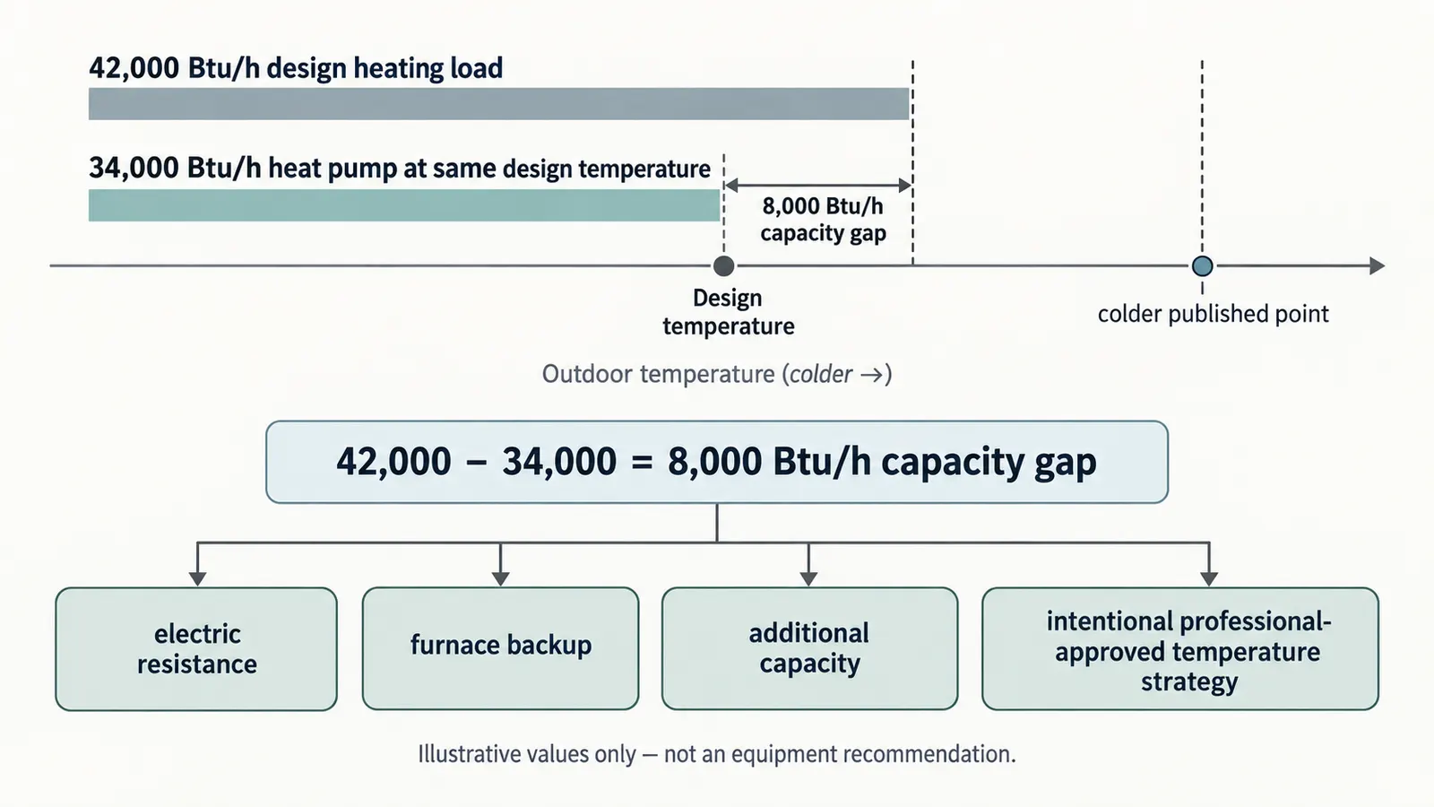
The capacity-gap formula is:
capacity gap = max(0, design heating load − delivered primary capacity)
If the load is 42,000 Btu/h and the heat pump delivers 34,000 Btu/h at the design temperature, the illustrative gap is 8,000 Btu/h. The designer can address it with more heat-pump capacity, another zone or system, electric resistance, a furnace, envelope changes or a deliberate acceptance of some indoor-temperature drift. The homeowner should not select the remedy from the formula alone.
The DOE cold-climate sizing guide gives two example strategies: 100–115% of estimated load at design temperature without auxiliary heat, or 75–85% of load with enough supplemental heat to make up the difference, with supplemental heat off unless needed. Read the source's sizing strategy. Those ranges illustrate a design conversation; they are not a mandate to oversize or undersize your system.
Verify refrigerant transition status
Refrigerant compliance is part of design freeze because a new home is a new system installation, not a replacement repair. EPA's current Technology Transitions table lists a 700-GWP limit and a January 1, 2025 installation compliance date for stationary residential and light-commercial air-conditioning and heat-pump systems, while showing an exception when all specified components were manufactured or imported before January 1, 2025. Check EPA's current sector table.
EPA's homeowner FAQ also says a new residential split system includes a system installed in a newly constructed home and states that a new split system installed after January 1, 2026 must use refrigerant with GWP below 700. Because the current sector table identifies a pre-2025 component exception and regulatory pages can change, have the HVAC designer or installer record the exact refrigerant, each specified component's manufacture/import status, project installation timing and compliance basis. Read EPA's FAQ for the new-system interpretation.
This federal check does not answer state, local or AHJ questions. It also does not tell you whether a mildly flammable refrigerant system is suitable for the proposed room, charge, installation method or local adoption of safety standards. Do not substitute “new refrigerant” or “EPA compliant” for the exact model, installation manual and local review.
Check controls and switchover logic
Request the control sequence in plain language and as a wiring or sequence diagram. It should answer:
- what sensor measures outdoor temperature;
- what sensor measures indoor temperature and where it is located;
- what calls compressor heating, furnace heating, resistance heating and emergency mode;
- whether compressor and backup can run together;
- what locks out the compressor or furnace;
- how defrost is detected and supported;
- what delay or staging logic prevents unnecessary backup;
- what a sensor or communication failure does;
- how a homeowner resets a nuisance lockout;
- which settings are installer-only and how they are recorded.
Carrier's homeowner explanation correctly identifies that auxiliary heat fills the capacity gap when a heat pump struggles, and that defrost and rapid thermostat recovery can call for backup. See the manufacturer's auxiliary-heat explanation. Treat the article's “often” temperatures and examples as product education, not a universal balance point. Your exact thermostat and equipment manual control the actual sequence.
For dual fuel, require a switchover setting and a commissioning test at the chosen threshold. For heat pump plus electric backup, require a test of each resistance stage, the combined service demand and the control lockout. For furnace-first systems, test cooling and heating calls separately and verify that the thermostat does not energize conflicting outputs.
Assign warranty and service responsibility
The warranty is only as useful as the record that proves which party owns a failure. Add a responsibility table to the contract:
| Deliverable | Responsible party | Evidence at handoff | Homeowner acceptance question |
|---|---|---|---|
| Load calculation | HVAC designer | Signed calculation and assumptions | Does it match the final envelope and floor plan? |
| Equipment selection | HVAC designer | Submittal and performance data | Are exact models and design-point outputs shown? |
| Electrical service | Electrical professional/utility | Load calculation, approval or utility record | Does it include backup stages and other large loads? |
| Fuel service | Utility, propane supplier or fuel contractor | Availability, connection and delivery scope | Are extension, meter, tank and regulator included? |
| Duct and distribution | HVAC designer/installer | Drawings, airflow and pressure record | Are all rooms and returns addressed? |
| Refrigerant installation | Qualified HVAC installer | Model, charge, leak/pressure/commissioning record | Does the record match the new-system compliance basis? |
| Combustion and venting | Qualified fuel/HVAC professional | Appliance, vent and inspection records | Is the combustion-air and vent route documented? |
| Controls commissioning | HVAC installer/controls professional | Sequence test and settings | Was every heat source and lockout tested? |
| Warranty registration | Installer or homeowner per terms | Registration confirmation and manuals | Who handles the first service call? |
DOE says oversizing, improper charging and leaky ducts can cause efficiency losses, discomfort and shortened equipment life, and it recommends regular maintenance and heat-pump-specific controls. Use DOE's installation guidance in the contract scope. A product warranty does not automatically cover design errors, duct defects, labor, service calls, refrigerant loss or utility upgrades.
The next decision is an order-release gate: no equipment is ordered until the exact model record, capacity, service, fuel, refrigerant and control responsibilities are complete.
Run the handoff to design freeze and protect the next decision #
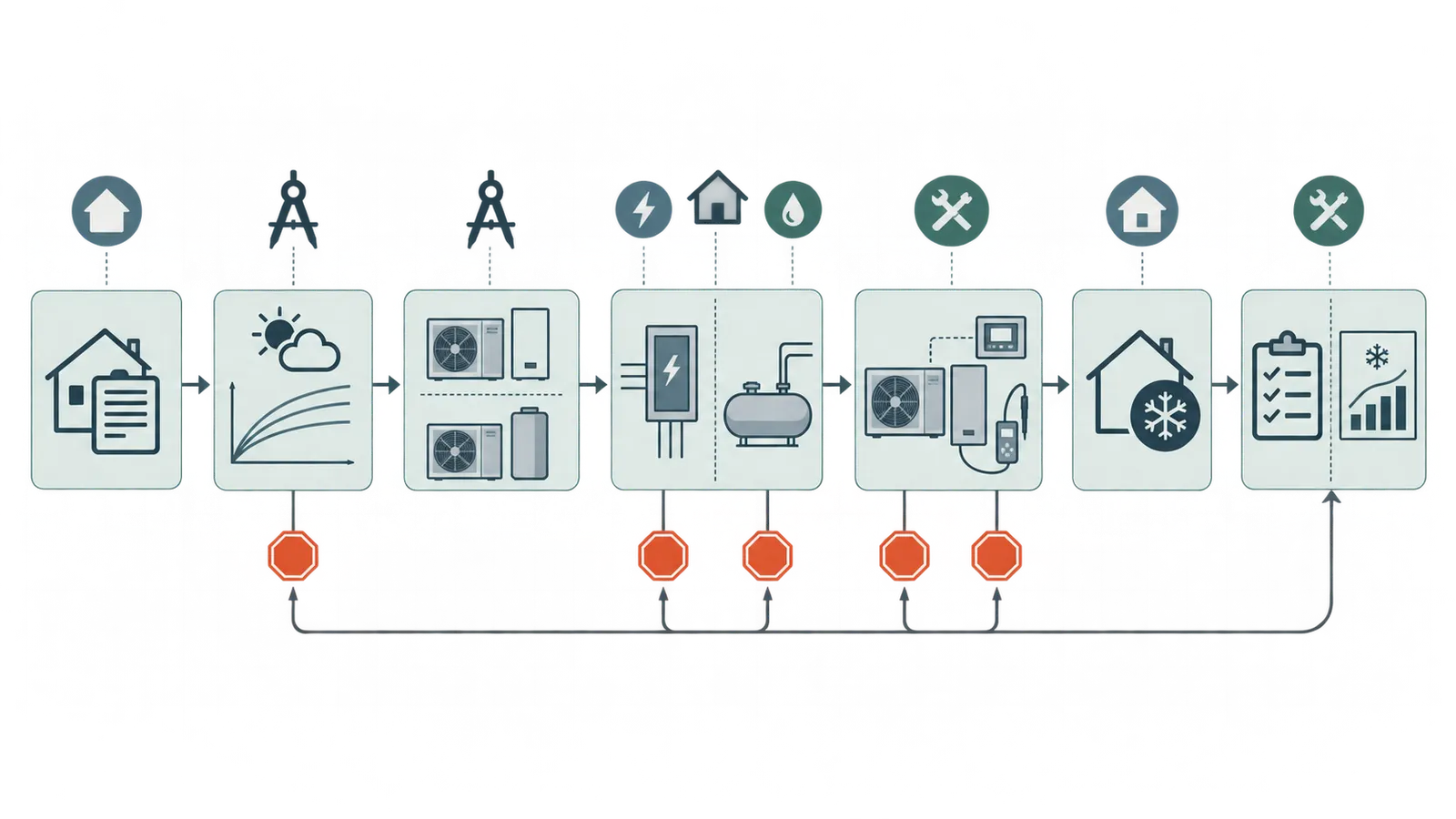
Use a staged handoff with objective stop points: define the common inputs, shortlist complete paths, model cost and sensitivity, verify prerequisites, confirm documents, freeze the system basis, then carry commissioning and ownership records into construction and handover. The homeowner's job is to ask for evidence and make the choice explicit; hazardous installation, engineering and code decisions remain with qualified local professionals.
Gate 1: homeowner brief
Before the HVAC designer begins, record the non-negotiables and preferences:
- target indoor temperatures and comfort variation you will accept;
- cooling and humidity expectations;
- tolerance for combustion equipment indoors or on the site;
- fuel availability and willingness to add service;
- electrical-service constraints or electrification goals;
- outage scenario and resilience duration, if any;
- maintenance involvement and local service availability;
- noise, appearance and outdoor-unit placement constraints;
- space reserved for mechanical equipment and future replacement;
- budget range and whether capital cost or operating-cost certainty has priority;
- expected construction and occupancy dates, which affect equipment availability and compliance timing.
This is a design brief, not a promise that every preference can be met. Use the Brictale materials and systems route to keep envelope, HVAC, electrical and equipment-room choices together, and the contractor-scope route to make the responsibilities visible in proposals.
Gate 2: comparable candidate package
Ask the HVAC designer or bidders for the same submittal format for every path. A fair package contains:
- load and design conditions;
- equipment models and capacities;
- capacity gap and backup logic;
- electrical and fuel prerequisites;
- duct and distribution concept;
- outdoor and indoor space requirements;
- controls sequence;
- refrigerant and compliance record;
- installation, commissioning and warranty scope;
- capital cost and operating-cost assumptions;
- exclusions and allowances;
- next decision and deadline.
Reject a comparison when one path includes a service upgrade and another assumes existing service; when one includes ducts and another does not; when a dual-fuel furnace is priced without fuel connection; or when a furnace-plus-cooling path omits the cooling coil, condenser, condensate, controls or refrigerant record.
Gate 3: verification meeting
Hold one meeting with the homeowner, HVAC designer, electrical professional, builder and serving utility or fuel supplier where their decisions overlap. Use the worksheet live. For each candidate, ask the responsible person to answer:
- What input are you relying on?
- What document proves it?
- What is still an allowance or assumption?
- What happens if the final window, insulation, floor plan or service changes?
- What is the most likely failure at installation or first winter?
- How will we observe or test it?
- Who fixes it and who pays if the scope was incomplete?
- What is the next handoff?
The meeting should produce action items, not just a preferred brand. Use a simple action log:
| Open item | Impacted paths | Owner | Evidence due | Decision if unresolved |
|---|---|---|---|---|
| Design temperature method not stated | All | HVAC designer | No capacity comparison | |
| Service calculation excludes resistance stage | All-electric with backup | Electrical professional | Recalculate before quote | |
| Gas availability not confirmed | Dual fuel/furnace | Utility or fuel supplier | Remove or price connection | |
| Exact indoor/outdoor match missing | Heat-pump paths | HVAC designer | No order release | |
| Refrigerant compliance basis missing | Any refrigerant system | Installer/designer | Hold procurement | |
| Switchover sequence not written | Dual fuel | HVAC designer/controls | Treat as incomplete |
Gate 4: design-freeze record
Freeze the following, with revision date and responsible approval:
- selected path and rejected alternatives;
- jurisdiction and AHJ contact or permit path;
- design heating and cooling loads;
- heating and cooling design temperatures;
- indoor setpoints and ventilation assumptions;
- equipment models and matched record;
- delivered capacity and input at design and colder conditions;
- capacity-gap treatment;
- backup type, stage size and trigger;
- electrical service and circuit basis;
- fuel service, venting and condensate basis;
- equipment locations and access clearances;
- duct/distribution drawings and airflow assumptions;
- controls sequence and sensor locations;
- refrigerant and EPA compliance record;
- installation, commissioning and warranty responsibilities;
- capital-cost allowances and operating-cost model inputs;
- homeowner acceptance criteria;
- next handoff into construction.
The construction team should receive this record with the approved drawings, not a verbal summary. If a substitution is proposed later, treat it as a change to the heating path and rerun the affected gates. Use the Brictale construction route for decision and change tracking, and the handover route to preserve manuals, commissioning records, warranty registration and maintenance information.
Gate 5: commissioning and first-season verification
Commissioning is where the modeled choice meets the installed home. The homeowner can observe and retain records, but should not perform refrigerant, gas, electrical or combustion testing. Ask the qualified installer for:
- installed model numbers and serial numbers;
- startup and commissioning report;
- measured airflow and external static pressure where applicable;
- refrigerant or sealed-system commissioning record as required by the equipment and applicable rules;
- temperature and control-response checks;
- resistance-stage and furnace-stage tests;
- defrost and switchover tests where applicable;
- condensate drainage test;
- combustion safety, venting and carbon-monoxide test where applicable;
- thermostat settings, lockouts and installer parameters;
- filter size and maintenance instructions;
- warranty registration and service contact;
- as-built drawings and photographs of concealed routes where the builder's process includes them.
During the first heating season, keep an observation log. Record date, outdoor temperature, indoor temperature by representative zone, thermostat mode, whether backup or furnace operation was shown, unusual noise, frost or ice behavior, comfort complaint, filter condition and any service response. Do not infer a refrigerant leak, unsafe combustion or electrical fault from a display or a single observation. Call the responsible professional.
Common failure cases and safe responses
| Observation | What it may mean | What not to infer | Safest next step |
|---|---|---|---|
| AUX appears in mild weather | Fast recovery, sensor/control issue, airflow issue, low charge or other fault | That the heat pump is necessarily undersized | Record outdoor temperature and call installer for control and equipment diagnosis |
| Furnace runs while heat pump is expected | Switchover setting, lockout, sensor or demand logic | That dual fuel is operating at the cheapest point | Request the control sequence and commissioning test |
| Home is cold in one room | Room load/distribution, envelope, airflow or thermostat location | That the central unit needs a larger nominal size | Have designer/installer measure airflow and compare room load |
| Outdoor unit is iced | Normal defrost condition or drainage/airflow/refrigerant problem | That adding a cover or removing ice yourself is safe | Keep clear; call qualified HVAC service if ice persists or airflow is blocked |
| Breaker trips during cold weather | Service demand, resistance stage, wiring or equipment fault | That a larger breaker is the fix | Do not reset repeatedly; call qualified electrical/HVAC professional |
| CO alarm activates near furnace | Potential combustion or alarm issue | That opening a window solves it | Leave as appropriate for the alarm instructions and contact emergency/qualified service; do not operate the appliance until cleared |
| Utility bill is higher than model | Weather, rates, backup hours, envelope, controls, fan or model assumptions | That the equipment rating was false | Compare the log and meter data with the model; request diagnosis |
| Proposed substitute uses different refrigerant | Procurement or availability change | That it is interchangeable | Hold installation; require updated manufacturer and compliance review |
Safety matters because this decision crosses several hazards. Electrical service work, panel work, line-voltage circuits and generator connections belong to qualified electrical professionals. Gas, propane, venting, combustion-air, carbon-monoxide and appliance work belong to qualified professionals under the applicable jurisdiction. Refrigerant recovery, charging, brazing, leak testing and installation of equipment with the applicable refrigerant safety requirements belong to qualified HVAC technicians. Work at height, lifting outdoor equipment and roof or attic access require appropriate professionals and fall protection. The homeowner may review documents, observe non-invasive operation from a safe occupied area and keep logs; the homeowner should not open energized panels, take refrigerant, gas or static-pressure readings, perform leak, combustion or carbon-monoxide testing, inspect suspected contamination, handle refrigerant, or enter an attic, crawlspace or other confined mechanical area to investigate a fault. Do not interpret permit or code compliance from a remote observation. Escalate equipment observations to the qualified local HVAC, electrical or fuel professional named in the responsibility record, and direct permit, inspection or adopted-code questions to the AHJ for the actual state, county, city or other jurisdiction. If a carbon-monoxide alarm or other emergency condition occurs, follow the alarm or emergency instructions, leave when directed and contact emergency services or qualified local help; do not operate the appliance until it is cleared.
When to stop and reopen the decision
Reopen the comparison if any of these changes:
- conditioned floor area or room layout;
- window, insulation, air-sealing or ventilation specification;
- heating or cooling load;
- design temperature method;
- outdoor unit, indoor unit, coil, air handler or furnace model;
- refrigerant or component manufacture/import timing;
- electrical service, water heating, cooking, vehicle charging or generator plan;
- gas or propane availability, pressure, tank or meter location;
- duct location, zoning or thermostat plan;
- builder scope, installer, warranty or service territory;
- utility rate structure or incentive assumption that materially changes the model;
- construction date that affects equipment availability or federal compliance documentation.
Do not treat a substitution as a cosmetic freshness update. Record the new date because the substance changed, then rerun the affected evidence and responsibility gates.
Use the worksheet to choose the next decision, not a national winner #
Choose the heating path by eliminating hard failures first, then comparing the remaining paths with transparent performance and cost assumptions. The final decision should be a signed or otherwise acknowledged handoff record that a designer, builder, installer and homeowner can all use.
The one-page homeowner worksheet
Copy this table into the project record. Blank fields are useful: they show what must be verified.
| Field | Home/project value | All-electric HP | HP + electric backup | Dual fuel | Furnace + separate cooling |
|---|---|---|---|---|---|
| Jurisdiction/AHJ | |||||
| Heating design temperature (°F) | |||||
| Design heating load (Btu/h) | |||||
| Design cooling load (Btu/h) | |||||
| Indoor setpoint (°F) | |||||
| Primary model(s) | |||||
| Delivered heat at design (Btu/h) | |||||
| Capacity gap (Btu/h) | |||||
| Colder-point capacity (Btu/h) | |||||
| COP, input or AFUE at cited point | |||||
| Backup type and capacity | |||||
| Backup trigger/switchover | |||||
| Electric service impact | |||||
| Fuel infrastructure impact | |||||
| Cooling equipment included? | |||||
| Duct/distribution scope | |||||
| Refrigerant and compliance record | |||||
| AHRI reference or other certification record | |||||
| Installation and commissioning scope | |||||
| Warranty and service record | |||||
| Capital-cost assumptions | |||||
| Modeled cost per delivered heat unit | |||||
| Rate/COP/backup sensitivity result | |||||
| Hard prerequisite status | |||||
| Responsible verifier | |||||
| Next handoff/date |
The decision rule
Use this sequence:
- Reject or hold any path without a valid load basis, design temperature, exact equipment data or responsible verifier.
- Reject or price any path that lacks electric service, fuel, venting, space, distribution or permit feasibility for the actual project.
- Calculate the capacity gap at the design condition and document how the gap is served.
- Model operating cost with local rates and separate capital cost, then test electricity rate, fuel rate, COP, design temperature and backup hours.
- Score comfort, resilience, maintenance, service access and future replacement using the homeowner's stated priorities.
- Verify manufacturer pairing, AHRI record, controls, refrigerant and warranty before procurement.
- Freeze the selected path with alternatives, assumptions, scope boundaries, commissioning criteria and the next construction handoff.
The right result may be an all-electric heat pump, a heat pump with carefully limited electric backup, dual fuel, or a furnace with separate cooling. The worksheet is successful when it makes the reason visible and makes a later substitution expensive to hide. It should also tell you what to do next: obtain the missing load record, request a service calculation, confirm fuel availability, revise the mechanical room, ask for model data, or move the verified package into the builder's construction scope.
The final limitation remains important: this article does not select equipment for your home. It organizes the evidence and decisions so the people who are responsible for design, permitting, utility coordination, installation and commissioning can do that work with fewer hidden assumptions. Preserve the record through design, budgeting, contractor scope, construction and handover, updating it only when a substantive project or evidence change occurs.
Heating-Path Design-Freeze Worksheet
A printable source-derived worksheet for comparing four new-home heating paths, recording capacity and cost inputs, and documenting professional verification before design freeze.
Download the worksheet (PDF)Cite this guide
Brictale. “How to Compare New-Home Heating Energy Paths Before Design Freeze.” Published 2026-09-25; updated 2026-09-25.
https://brictale.com/build/materials/compare-new-home-heating-energy-paths-before-design-freeze · Read the Markdown version
Original contribution: Heating-path design-freeze worksheet and decision matrix. A source-derived record for comparing four complete new-home heating paths against the calculated load, design temperature, cooling need, service and fuel prerequisites, resilience goals, operating-cost assumptions, controls, compliance and handoff evidence.
Sources and scope
Evidence behind this page
- For new construction or a full heating-system replacement, the DOE Building Science Education sizing guide says to follow ACCA Manual J or equivalent load calculations and use manufacturer-published performance at design conditions to identify adequate heating and cooling capacity.
Guide To Sizing & Selecting Air-Source Heat Pumps in Cold Climates
U.S. cold-climate air-source heat-pump sizing guidance for new construction or gut rehabilitation; applies to load calculation, design condition and manufacturer performance-data review, not a site-specific design approval.
Accessed · Link to this claim - The DOE Building Science Education sizing guide presents two source-derived strategies: match capacity at design temperature to 100–115% of estimated heating load without auxiliary heat, or size to 75–85% of load and include enough supplemental heat to make up the difference; supplemental heat should be off unless needed.
Guide To Sizing & Selecting Air-Source Heat Pumps in Cold Climates
DOE-hosted guidance derived for cold-climate air-source heat pumps; these are sizing strategies to discuss with a designer, not a universal code requirement or a recommendation for every home.
Accessed · Link to this claim - ENERGY STAR's February 2026 cold-climate criteria require a certified residential heat pump to demonstrate COP of at least 1.75 at 5°F, at least 70% of 47°F heating capacity at 5°F, and native-controls verification at the low-ambient test point.
ENERGY STAR certification criteria for covered residential heat pumps; the test points are certification evidence, not a promise of a particular home's delivered capacity, bill or comfort.
Accessed · Link to this claim - ENERGY STAR defines COP as the ratio of the average rate of space heating delivered to the average rate of electrical energy consumed by the heat pump at a single set of operating conditions.
Heat Pump Equipment Key Product Criteria
ENERGY STAR terminology for heat-pump performance; COP is a point-condition metric and should not be substituted for seasonal performance or a whole-home operating-cost forecast.
Accessed · Link to this claim - EPA's current Technology Transitions table lists a 700-GWP limit and a January 1, 2025 installation compliance date for stationary residential and light-commercial air-conditioning and heat-pump systems, with an exception when all specified components were manufactured or imported before January 1, 2025.
Technology Transitions HFC Restrictions by Sector
U.S. federal EPA Technology Transitions table for the residential and light-commercial air-conditioning and heat-pump subsector; does not replace state, local or AHJ requirements.
Accessed · Link to this claim - EPA's homeowner FAQ says a new residential split system includes a system installed in a newly constructed home and states that a new split system installed after January 1, 2026 must use refrigerant with GWP below 700; it also says existing systems can be repaired with compatible components.
Frequent Questions on the Phasedown of Hydrofluorocarbons
U.S. federal EPA FAQ for residential split-system interpretation; the current sector table contains a pre-2025 component exception, so the project record must document the exact equipment and compliance basis.
Accessed · Link to this claim - AHRI's public directory supports searching by AHRI reference number or model number and provides certificates of product ratings for certified product-performance records, including residential heat pumps, coils and furnaces.
AHRI Directory of Certified Product Performance
AHRI public certification directory and its residential product categories; availability of a record does not verify the proposed installation, duct design, controls, clearances or local compliance.
Accessed · Link to this claim - DOE explains that air-source heat pumps transfer heat rather than generate it, can provide both space heating and cooling, and that local climate conditions affect their operation because outdoor air is the heat source and heat sink.
Purchasing Energy-Efficient Residential Air-Source Heat Pumps
DOE federal purchasing guidance and explanatory material for residential air-source heat pumps; its example rates and equipment assumptions are not a homeowner's local forecast.
Accessed · Link to this claim - DOE says oversizing, improper charging and leaky ducts can cause efficiency losses, occupant discomfort and shortened equipment life, and recommends heat-pump-specific thermostats and regular maintenance such as refrigerant charging and filter replacement.
Purchasing Energy-Efficient Residential Air-Source Heat Pumps
DOE installation and use guidance for residential air-source heat pumps; maintenance intervals and commissioning steps remain product- and installer-specific.
Accessed · Link to this claim - Carrier's homeowner explanation describes auxiliary heat as a secondary source that can supplement a heat pump during capacity shortfall, rapid thermostat recovery and defrost, while noting that the exact trigger depends on the equipment and controls.
What Is Auxiliary Heat? Definition, Meaning & How It Works
Carrier U.S. homeowner education for auxiliary heat; examples such as outdoor temperatures and thermostat increases are product education, not a universal balance point or a substitute for the proposed system's control manual.
Accessed · Link to this claim - ENERGY STAR's residential furnace criteria define AFUE generally as the percentage of incoming fuel converted to space heat and set certification thresholds of at least 97% AFUE for its U.S. North region and at least 95% AFUE for its U.S. South region.
ENERGY STAR certification thresholds and its listed U.S. North/South state groupings for residential gas furnaces; not a national code requirement and not a delivered-heat guarantee.
Accessed · Link to this claim - DOE Building Science Education explains that direct-vent combustion appliances bring combustion air from outdoors and exhaust byproducts through a sealed second pipe; it identifies backdrafting as combustion products being drawn indoors by negative pressure and calls sealed direct vent the safest usual choice for conditioned-space combustion appliances.
DOE Building Science Education explanation of combustion equipment and backdrafting; the local mechanical designer must select a compliant appliance, venting route and safety controls for the jurisdiction.
Accessed · Link to this claim - DOE's residential heat-pump cost examples explicitly use assumed electricity prices and operating-hour assumptions, state that energy savings vary with actual usage, and direct users to a residential heating-and-cooling cost calculator for their application.
Purchasing Energy-Efficient Residential Air-Source Heat Pumps
DOE example methodology and limitations; not a current national residential rate forecast or a quote for any utility territory.
Accessed · Link to this claim