How to Compare 1-Inch and 4-Inch HVAC Filter Cabinets Before a New-Home Design Freeze
Compare 1-inch and 4-inch HVAC filter cabinets by airflow, pressure drop, access, replacement media, cost, and commissioning—not MERV alone.
The short answer
Choose the cabinet depth only after the HVAC designer identifies the exact air handler, design airflow, blower limits, and filter pressure-drop data. Compare nominal face area and media depth, but also reserve the system’s static-pressure budget, confirm a reachable replacement route, and require the installer to document the filter model and commissioning measurements before rough-in is closed.How to Compare 1-Inch and 4-Inch HVAC Filter Cabinets Before a New-Home Design Freeze
Choose the cabinet depth only after the HVAC designer identifies the exact air handler, design airflow, blower limits, and filter pressure-drop data. Compare nominal face area and media depth, but also reserve the system’s static-pressure budget, confirm a reachable replacement route, and require the installer to document the filter model and commissioning measurements before rough-in is closed.
Freeze the inputs before you compare cabinet depth #
The right depth is the one that the selected ducted HVAC system can support at its design airflow, fits the planned return path, and leaves the homeowner with a practical replacement and verification routine. A 4-inch cabinet is not automatically better than a 1-inch rack, and a 1-inch rack is not automatically wrong. The decision is incomplete until the exact equipment, airflow, filter data, access route, and handoff record are known.
This is a new-home design decision, not a last-minute filter-shopping decision. The cabinet occupies space in the return-air path. Its depth affects the transition, framing, service clearance, filter availability, and the pressure the blower must overcome. The replacement media then changes resistance as it loads with dust. If those facts are postponed until the air handler arrives, the installer may have to accept a compromised location, cut an undersized opening, substitute an undocumented filter, or tell you that a higher-efficiency media is not compatible after the return is already closed.
DOE describes filters in ducted heating and cooling systems as return-side components that protect the HVAC motor and improve indoor air quality, and it specifically says they should be in a location that the homeowner can access for replacement or cleaning. That is the basic design test: the filter is part of the air-moving system and part of the ownership system, not a loose accessory added after the ductwork is designed. See DOE’s guidance on proper HVAC filter installation.
The decision record to create
Before asking two contractors or equipment suppliers to compare options, create one identical brief for both. It should contain:
- The equipment type: furnace and split air conditioner, packaged unit, ducted heat pump, or another ducted configuration.
- The exact proposed air-handler or furnace model, including revision or configuration information shown on the submittal.
- The design airflow in cubic feet per minute (cfm), and whether that number is for cooling, heating, ventilation, or a particular blower mode.
- The blower type if known, such as a permanent split capacitor (PSC) or electronically commutated motor (ECM). Do not infer the motor from a marketing phrase such as “variable speed.”
- The proposed nominal filter height and width, in inches; the media depth; the cabinet’s actual outside dimensions; and the connection dimensions.
- The candidate filter’s exact manufacturer, part number, nominal size, actual size if published, MERV rating or other efficiency claim, and pressure-drop data at the design airflow or at a clearly stated face velocity.
- Clean pressure drop and the condition used for any loaded, replacement, or maximum pressure-drop value.
- The fan-table or approved external-static-pressure criterion, its defined test points, and the components already included in that value. Separately list filter, coil, cabinet, damper, grille, transition, and duct drops, with the designer marking which are inside the criterion so none is counted twice.
- The access route: room, closet, attic, crawlspace, return grille, or another location; the direction the filter is removed; the clearance needed to slide it out; and whether a person can reach it without standing on unstable surfaces.
- Replacement-media part numbers, sources, lead time, availability in your area, unit cost input, expected replacement basis, and who will order and install it.
- The person responsible for each verification: HVAC designer, equipment supplier, installer, builder, commissioning technician, or homeowner.
Do not accept “standard 16 by 25 filter” as a complete specification. A nominal size is a naming convention, not a complete description of the cabinet, door, gasket, media depth, or actual opening. One manufacturer’s product page, for example, lists a 1410 air purifier with a nominal 16 by 25 inch filter but actual cabinet measurements of 17.75 by 6.75 by 30.167 inches and specified replacement media models. That is a product-specific example, not a universal dimension; it shows why the nominal size and the cabinet footprint belong in separate worksheet fields. Review the Aprilaire 1410 product dimensions and media information only as an example of the information to collect.
Who owns each input
The homeowner owns the requirement and the usability test. You can decide that a filter must be replaceable from a finished floor, that a replacement must be orderable from more than one source, or that the maintenance record must be delivered at handover. You do not need to select the pressure drop yourself.
The HVAC designer or contractor owns the equipment match and the airflow design. That professional should identify the selected air handler or furnace, determine the design airflow, select the return arrangement, and show how the filter’s resistance fits within the equipment’s allowable external static pressure. The cabinet manufacturer owns the accuracy of its published dimensions, filter compatibility, and performance data. The installer owns physical fit, orientation, sealing, support, and the installed configuration. The builder coordinates the location with framing, insulation, access panels, ceilings, doors, and other trades. A commissioning technician, where engaged, verifies operating measurements and records them.
Your job is to keep the handoffs visible. If the equipment model changes, the filter comparison must be repeated. If the filter model changes, the pressure-drop and replacement-media checks must be repeated. If the cabinet moves from a utility room to an attic, the access and safety check must be repeated. “The substitute is equivalent” is not a verification record unless the exact inputs are compared.
The compact originality brief
Current answers usually explain MERV, say that a dirty or high-efficiency filter can increase resistance, and note that deeper media can offer more surface area. Manufacturer manuals explain how to install and replace one brand’s media. The missing decision is the handoff between those facts: how a homeowner compares a 1-inch rack with a 4-inch cabinet while recording the exact equipment, airflow, pressure budget, access, and commissioning evidence.
The original contribution here is the Filter-cabinet comparison worksheet: a reproducible worksheet for comparing depth, face area, pressure drop, access, cost, and commissioning. Record the same inputs for each candidate, calculate face area and pressure budget, then choose only after model-specific verification. This is an illustrative decision aid, not a substitute for the selected equipment manual, design calculations, local requirements, or commissioning by a qualified HVAC professional. You can check the contribution by giving the completed worksheet to the HVAC designer and asking whether every input matches the equipment submittal, filter data, physical opening, and final commissioning record.
Your next decision after this section is whether each candidate has enough complete information to be compared. If either candidate lacks exact pressure-drop data at a relevant airflow, mark it “not yet comparable,” not “probably fine.”
Compare what 1-inch and 4-inch filters actually change #
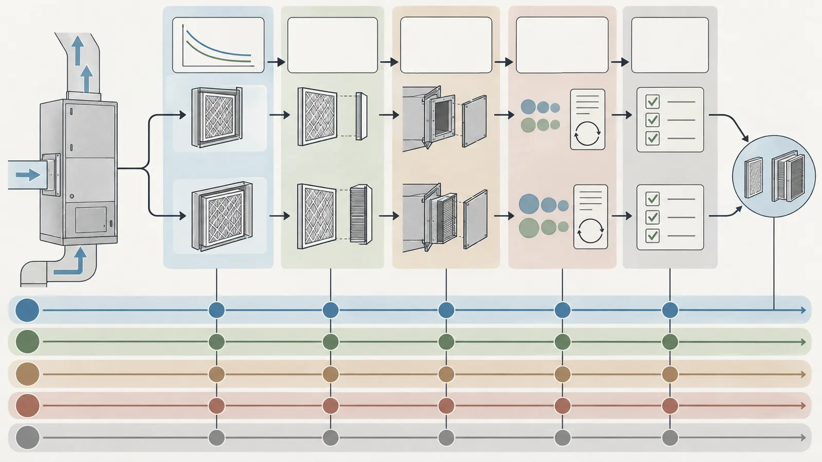
A 1-inch rack and a 4-inch cabinet differ mainly in available media geometry, replacement format, cabinet depth, and the way air reaches the filter; neither depth alone tells you the resulting pressure drop. Compare face area first, then the manufacturer’s pressure curve at your airflow, then physical access and ownership cost. Treat MERV as an efficiency descriptor that must be evaluated alongside resistance and the equipment’s capability.
Depth is not the same as face area
For a rectangular filter, nominal face area is:
face area (ft²) = nominal height (in) × nominal width (in) ÷ 144
For an illustrative 20 by 25 inch filter:
20 in × 25 in ÷ 144 = 3.47 ft²
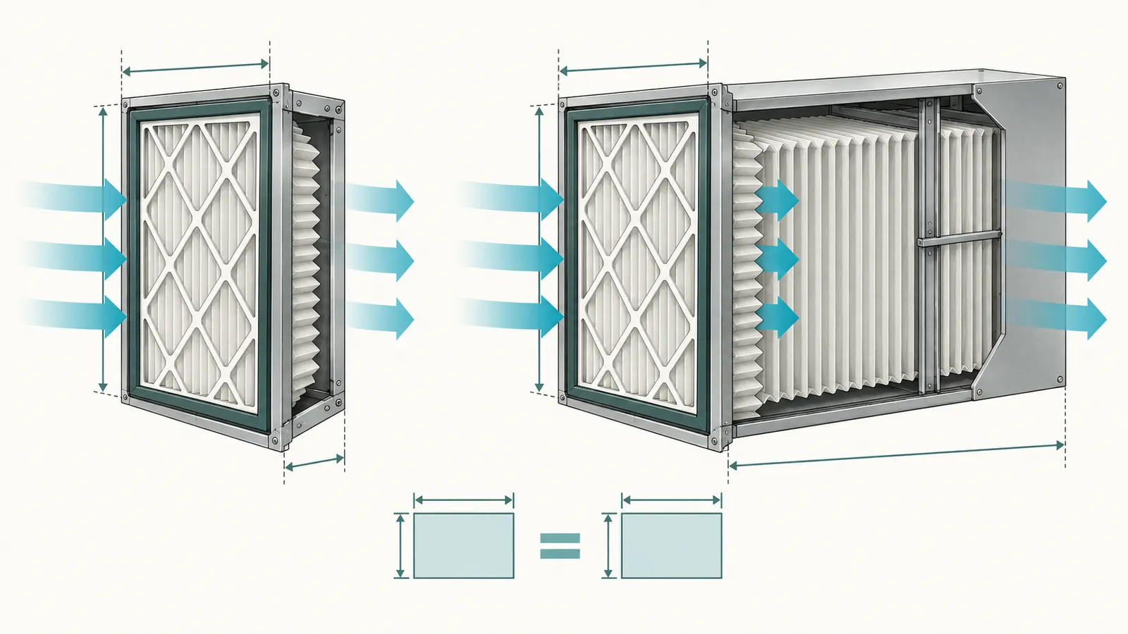
If both the 1-inch and 4-inch candidates use the same 20 by 25 nominal face, the face area is the same. The deeper cabinet may allow more pleated media area within that face, but it does not magically make the opening four times wider. If the 4-inch design also uses a larger face, a second return, or a different orientation, calculate those changes separately.
The useful comparison is the amount of media presented to the airflow and the velocity through that media, not the number printed on the cabinet door. A deeper pleat can provide more media surface in the same nominal opening. DOE’s Building America summary explains that pressure drop can be reduced by increasing filter surface area through larger dimensions, deeper pleats, or multiple return-air filters; it gives the specific example that a 4-inch pleat has twice the surface area of a 2-inch pleat. That is a mechanism, not a promise that every 4-inch filter will have half the pressure drop of every 1-inch filter. Read the DOE filter-sizing research summary with the exact product data.
A 1-inch rack can be reasonable when its data and airflow work
A 1-inch arrangement may be reasonable when the selected equipment’s pressure budget supports the chosen media at design airflow, the return and grille area are sized for the airflow, a compatible filter with current pressure data is available, and the homeowner can reach it. A 1-inch rack may also be a deliberate part of a return-grille strategy, especially where the air handler is inaccessible and the design provides filters at accessible return grilles.
Its potential weaknesses are limited media depth, higher face velocity when the face area is small, greater sensitivity to a restrictive pleat, and potentially more frequent replacement. Those are risks to test, not automatic failures. A large 1-inch face can have lower velocity than a small 4-inch face. A well-designed 1-inch filter can have lower resistance than a poorly selected deep filter. The only honest comparison is the actual filter at the actual airflow.
A 4-inch cabinet can buy design room, not permission to ignore the fan
A 4-inch cabinet often creates more media surface within the same general return opening and can make a higher-efficiency media easier to accommodate. It may also support longer service intervals for some products, but the interval belongs to the selected media and operating conditions, not to the “4-inch” label. It needs more depth behind or beside the air handler, a door or slide-out path, a transition that does not constrict the return, and a replacement path that remains available after cabinets, framing, or finished walls are installed.
Deep media also has failure modes. The cabinet can be deep but undersized in height or width. The media may be inserted in the wrong direction. A nominal 4-inch filter may not fit the rails of a particular cabinet. A door may be impossible to open once a water heater, shelving, wall, or furnace flue is installed. A high-efficiency filter can still consume more pressure than the fan or duct system can provide. Depth buys an option; it does not establish compatibility.
MERV is useful but incomplete
MERV, the Minimum Efficiency Reporting Value, describes particle-removal performance under a test classification. It does not state the filter’s pressure drop at your system’s cfm, the loaded resistance after dust accumulation, the cabinet’s gasket quality, or whether the filter will fit the slot. DOE describes MERV as a measure of how well a filter removes small particles, then discusses pressure drop as a separate resistance that can affect airflow and fan energy. The DOE profile on filter selection reports that filters with the same broad rating category can behave differently in testing.
The practical question is not “What is the highest MERV I can buy?” It is “What particle-efficiency claim is needed for this household and program, and what exact filter delivers it at an acceptable pressure drop, face area, replacement condition, and cost?” If the household has a specific health concern, do not convert this buying guide into a medical air-cleaning promise. Discuss the concern with an appropriate clinician or public-health source and have the HVAC professional evaluate the equipment consequences.
Use the four tests for each candidate
For each 1-inch and 4-inch candidate, ask four separate questions:
- Air-moving test: At the design airflow, what is the pressure drop of the exact clean filter? What value is used for a loaded or change condition?
- Geometry test: What are the nominal face dimensions, actual media dimensions, cabinet outside dimensions, connection dimensions, and available return area?
- Ownership test: Can the homeowner reach the filter, identify its orientation, purchase the exact replacement, and replace it without unsafe access or disassembly?
- Verification test: What will be measured or documented before close-up, and where will the record live?
Do not let a candidate pass because it wins only one test. A very low-pressure filter that cannot be reached will be neglected. A convenient filter with no pressure data cannot be compared responsibly. A deep cabinet installed after the equipment selection may force a transition that creates a new restriction. A complete choice satisfies all four.
Your next decision is whether you need a deeper cabinet, a larger face, more than one return filter, a different media construction, or simply better data for the existing 1-inch concept. That answer belongs in the pressure-budget worksheet.
Build a pressure-drop budget instead of choosing by MERV #
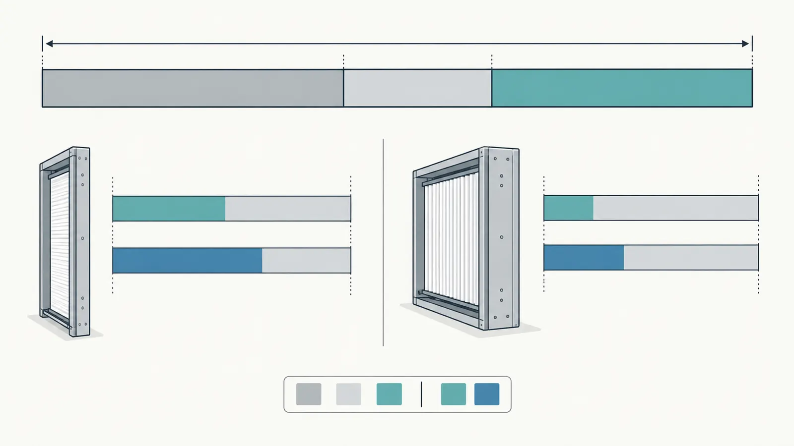
Choose between the cabinets only after the filter’s resistance fits inside the selected system’s approved external-static-pressure criterion at design airflow and at the planned replacement condition. The filter is one pressure-consuming component among several; the relevant accounting boundary is not a generic total-pressure number, the filter’s rating alone, or a “the blower is variable speed” statement.
What pressure drop means here
Pressure drop is the difference in static pressure across a component while air is moving through it. It is commonly recorded in inches of water column, written as in. w.c. or in. WC. A filter creates pressure drop because media resists the air passing through it. As media loads with dust, resistance can increase. The fan then either delivers less airflow, uses more power to maintain airflow, or operates outside the conditions assumed by the design, depending on the motor and controls.
Before calculating, define the accounting boundary. In this guide, the equipment criterion is the external-static-pressure value or fan-table point that the HVAC designer approves at the stated airflow, using the equipment manufacturer’s defined test points. It is a fan-capability or design criterion, not a total you create by adding every component name. A component drop is the pressure difference measured across one component between its upstream and downstream test points. The filter drop belongs to its own filter-face test points. Use only component drops that lie inside the same approved boundary and are not already included in the equipment data.
The DOE Building America profile uses the phrase “total system pressure drop” for historical context and describes about 0.4 or 0.5 in. WC as a common residential reference. That language must not be relabeled as the selected equipment’s external-static-pressure allowance or used to double-count a coil, cabinet, or other internal component. The figures are not a national code limit and do not assign 0.5 in. WC to your unit. The equipment manufacturer’s fan table, installation instructions, designer’s calculations, and local requirements control. Start with the DOE discussion of total system pressure and filter resistance, then request the exact model data and measurement boundary.
Use this boundary check before entering numbers:
| Item | Where the value belongs | What prevents double-counting |
|---|---|---|
| Fan-table or approved external-static-pressure criterion | The equipment-defined external test points at stated airflow and operating mode | Do not add it as another component drop; record its source and boundary |
| Filter pressure drop | Immediately upstream and downstream of the installed filter, with airflow and clean/change condition | Do not substitute a whole-system reading for the filter value |
| Coil or internal cabinet loss | Only where the designer confirms whether it is inside or outside the equipment criterion and fan data | Add or subtract it once, never by assumption |
| Return grille, transition, duct, or damper drops | Across each field component that lies within the approved boundary | Include only if not already embedded in the equipment value or another component total |
| Planning reserve | A separately named project assumption | Keep it visible; it is not a code requirement or an unnamed component loss |
The planning formula
Use this planning relationship for each candidate after the designer has confirmed the boundary:
allowable filter drop = approved external-static-pressure criterion − external component drops not already included − planning reserve
Record every term in the same unit, at a stated airflow and operating condition. The approved criterion may come from the manufacturer’s fan table or an approved design value. “External component drops” means only the components the designer confirms are within that boundary and not already included in the criterion. A coil or cabinet must have an explicit inclusion decision; do not list it automatically. “Planning reserve” is an explicitly identified planning choice, not a universal code value; if the designer does not use one, record zero and explain why.
Then compare both the clean and loaded or change-condition values:
candidate passes planning screen when clean drop ≤ allowable filter drop and change-condition drop ≤ allowable filter drop
Do not add a clean pressure drop from one product to a loaded pressure drop from another and call the result comparable. The test airflow, media area, filter condition, and measurement location must match. If the manufacturer reports pressure drop at 500 cfm but your design is 1,200 cfm, ask for the curve or an engineering interpolation. Do not treat a single-point number as a system result.
Illustrative pressure-budget calculation
The following is a modeled example to show the worksheet method. It is illustrative; it is not a measurement, product test, contractor quote, or recommendation.
Assume a proposed ducted system has these planning inputs:
- Equipment and design documents identify an approved fan-table/external-static-pressure criterion of
0.50 in. WCat the comparison airflow and at the equipment’s defined external test points. - The designer’s estimate for external return grille, duct, transition, and damper drops that are inside that same boundary and not already included in the criterion is
0.24 in. WC. - The designer separately confirms whether coil and internal cabinet losses are already represented by the equipment data; this illustrative subtraction does not add them a second time.
- The project team records an owner-requested planning reserve of
0.08 in. WCfor uncertainty and future loading. This reserve is a planning input, not a national requirement.
The pressure available to the filter under those explicitly bounded assumptions is:
0.50 − 0.24 − 0.08 = 0.18 in. WC
Now imagine the supplier’s illustrative comparison sheet reports:
| Candidate | Nominal filter | Media depth | Clean drop at 1,200 cfm | Change-condition drop at 1,200 cfm | Planning result |
|---|---|---|---|---|---|
| A | 20 × 25 in | 1 in | 0.14 in. WC | 0.22 in. WC | Does not pass the change-condition screen |
| B | 20 × 25 in | 4 in | 0.07 in. WC | 0.12 in. WC | Passes this illustrative screen |
Candidate A appears acceptable when clean but fails the stated replacement-condition screen. Candidate B uses less of the modeled filter allowance, but it still needs a physical fit, access, maintenance, and commissioning check. Neither row proves what a real filter will do. The numbers exist only to show how a homeowner can see the consequence of using both clean and loaded data.
Sensitivity: change one input at a time
The value of the worksheet is that it shows which unknown could reverse the choice. Use real supplier or design data when available. When it is unavailable, mark the row unresolved rather than creating a false precision.
| Change to the illustrative case | Calculation or question | Effect on the decision |
|---|---|---|
| Other component drop rises from 0.24 to 0.29 in. WC | 0.50 − 0.29 − 0.08 = 0.13 in. WC available for filter | Candidate A fails clean and change conditions; Candidate B’s 0.12 change value leaves only 0.01 in. WC |
| Design airflow rises from 1,200 to 1,400 cfm | Obtain each filter’s drop at 1,400 cfm or use the manufacturer curve | Do not scale pressure drop linearly unless the data method justifies it; a candidate can change order |
| The reserve is removed | 0.50 − 0.24 − 0.00 = 0.26 in. WC available | Both illustrative candidates pass the numeric screen, but the team has chosen to accept more uncertainty; document that choice |
| Dust load is higher than assumed | Request loaded or change-condition data for the actual media and household operating pattern | A candidate that passes clean may fail before its calendar replacement date |
| Face area increases to two filters | Recalculate total nominal area and ask how airflow divides between filters | Lower face velocity may reduce drop, but the second grille, cabinet, transitions, and access add design work |
The airflow row matters because pressure drop is not a fixed property of a filter independent of flow. DOE reports that its research measured pressure drop at multiple face velocities and developed performance curves for different filter and motor conditions. That is why a number without a test airflow is not enough. Read the DOE account of the filter research method and ask the supplier to state the curve’s units and test condition.
Do not overread motor type
The DOE summary reports different consequences for PSC and ECM motors. In the described sample, clean MERV 8 filters reduced PSC airflow by about 7%, while fan power increased about 9% on average for regulated-airflow ECM systems relative to the fiberglass reference. The same source describes risks such as reduced airflow, greater fan energy, leakage at weak paths, coil freezing in some conditions, or filter deformation when the system is not designed for the resistance. These results came from 13 tested filters and stated test conditions, not from a selected new-home system. Read the DOE research results and test scope before applying the numbers.
This does not mean an ECM makes any filter safe. It means the system may respond differently. A motor that maintains a target airflow can consume more electricity or operate near a limit. A motor that does not maintain airflow can deliver less capacity. The correct question for the HVAC professional is: “With this exact blower, equipment model, duct design, filter, and design airflow, what external static pressure and airflow are expected in clean and change conditions?” The DOE research results and limitations should be treated as context, not as a substitute for the selected fan table.
The allowable resistance label is useful when present
The DOE profile’s discussion of an equipment label is historical context from 2014, not a current code instruction. If your equipment has a manufacturer label, photograph it and copy the value into the worksheet with the model and revision. For a California single-family project, the California Energy Commission says buildings with permit applications submitted on or after January 1, 2026, must comply with the 2025 Energy Code. The CEC’s restructured 2025 California Code of Regulations Title 24, Part 6 text identifies Section 402.2.6.12 and its subsections for system air-filter sizing, service accessibility, permanent labeling of design airflow and maximum allowable clean-filter pressure drop, bypass prevention, efficiency, and clean-filter pressure drop; its bracketed cross-references identify the corresponding Section 150.0(m)12 provisions. See the CEC’s 2025 Energy Code scope and effective date and 2025 Title 24, Part 6 filter provisions. These are California-specific; confirm the adopted text, project type, compliance path, permit status, and enforcement with the authority having jurisdiction. If your project is elsewhere, do not copy California’s value or requirement into the local code column.
Your next decision is a data decision: if the filter supplier cannot provide pressure-drop information at the design condition, either select a product with usable data or have the HVAC designer establish a documented acceptance method. Do not fill the blank with the MERV number.
Use the filter-cabinet comparison worksheet #
Use one worksheet row per complete candidate, not one row for “1-inch” and one for “4-inch” in the abstract. A depth is not a product. The row should identify the media, cabinet, equipment, airflow, pressure condition, access, replacement path, and handoff evidence that make the candidate real.
Worksheet: identity and geometry
Copy this table into the project decision log and complete it with the designer or installer. “Unknown” is a useful status when it triggers an action; it is not a pass.
| Field | Candidate A: 1-inch concept | Candidate B: 4-inch concept | Who supplies or verifies it |
|---|---|---|---|
| Exact HVAC equipment model | HVAC designer or equipment supplier | ||
| Equipment type and heating/cooling modes | HVAC designer | ||
| Blower type and fan-control information | Equipment documentation and designer | ||
| Design airflow, cfm | HVAC designer | ||
| Nominal filter height, inches | Filter/cabinet data | ||
| Nominal filter width, inches | Filter/cabinet data | ||
| Face area, ft² | height × width ÷ 144 | height × width ÷ 144 | Homeowner checks arithmetic; designer checks design |
| Media depth, inches | Filter data | ||
| Actual filter dimensions | Filter data | ||
| Cabinet outside dimensions | Cabinet submittal | ||
| Connection opening and transition dimensions | HVAC designer and installer | ||
| Number of filter faces in the return path | Duct layout | ||
| Filter airflow direction and orientation mark | Manufacturer and installer | ||
| Gasket, door, rail, or seal detail | Cabinet manufacturer and installer |
When the candidate is a return grille rather than a central cabinet, record every grille’s nominal size and the total face area. Do not sum face areas without asking whether the air actually divides as the design assumes. A grille obstructed by furniture or a closed damper may not carry the intended share of airflow.
Worksheet: media and pressure data
| Field | Candidate A: 1-inch concept | Candidate B: 4-inch concept | Pass condition or action |
|---|---|---|---|
| Exact media manufacturer and part number | No generic “MERV 11 filter” entry | ||
| MERV rating or other efficiency claim | Record the claim, not a universal health conclusion | ||
| Clean pressure drop, in. WC | Must state airflow and test condition | ||
| Loaded, change, or maximum pressure drop, in. WC | Must state how the condition is defined | ||
| Pressure-drop source document and revision/date | Save the document with the project record | ||
| Equipment fan-table or approved external-static-pressure criterion, in. WC | Record exact test boundary, airflow, mode, and source | ||
| Pressure boundary and included components | Designer marks what the criterion includes | ||
| External component drops not already included, in. WC | Designer lists each component and its measurement points | ||
| Coil/internal cabinet inclusion decision | Add once only if the designer confirms it is outside the criterion | ||
| Planning reserve, in. WC | Explicit planning choice; not assumed code | ||
| Allowable filter drop, in. WC | criterion − external drops not already included − reserve | criterion − external drops not already included − reserve | Compare clean and change conditions |
| Airflow used for every pressure value, cfm | Same design point where possible | ||
| Filter pressure measurement points | Upstream/downstream of the installed filter | ||
| Static pressure measurement plan | Identify who measures and when | ||
| Unresolved pressure question | Assign an owner and due date |
The pressure columns should not contain a single value with no condition or boundary. A filter’s pressure drop changes with airflow and can change as the media loads. The DOE report’s research method—multiple face velocities, different filters, and different motor responses—is a useful reminder that the curve is part of the specification. Read the DOE source-selection and pressure-drop discussion before accepting a supplier’s isolated number. Have the HVAC designer initial or otherwise attribute the inclusion decision for every coil, cabinet, grille, transition, duct, and damper; that handoff is what prevents a component from being counted both inside a fan-table criterion and again as an external loss.
Worksheet: ownership and handoff
| Field | Candidate A: 1-inch concept | Candidate B: 4-inch concept | Verification record |
|---|---|---|---|
| Access location | Plan, elevation, or site photograph | ||
| Filter removal direction | Dimensioned clearance check | ||
| Finished-floor or safe-platform access | Builder and homeowner walk-through | ||
| Door, panel, grille, or rail can open fully | Physical mock-up or installed check | ||
| Replacement media part number | Manual, label, and supplier record | ||
| At least one practical replacement source | Current availability checked near handover | ||
| Replacement unit cost input | Owner enters dated price; not a national estimate | ||
| Expected changes per year or condition trigger | Manufacturer plus household plan | ||
| Annual media cost formula | unit cost × changes/year | unit cost × changes/year | Add service, delivery, and other owner costs |
| Filter orientation and installation instruction | Manual and cabinet label | ||
| Initial commissioning airflow and static pressure | Commissioning record | ||
| Outstanding issue before rough-in close | Written responsibility and date |
The “replacement unit cost input” is intentionally blank until the owner records a dated, local or currently available price for the exact part number. The worksheet should not manufacture a cost range. Use a comparison index if a dollar price is not yet available: 1.0 × for the lower-cost candidate, 1.5 × for a candidate whose unit price is fifty percent higher, or another clearly labeled planning factor. Then replace the factor with a real price before the budget is finalized.
Worked face-area and velocity example
This example demonstrates calculations only. It is illustrative and does not represent a measurement or a preferred filter size.
Suppose the selected system’s design airflow is 1,200 cfm and the proposed central opening is 20 by 25 inches for both candidates:
face area = 20 × 25 ÷ 144 = 3.47 ft²
The nominal face velocity estimate is:
face velocity = airflow ÷ face area
1,200 cfm ÷ 3.47 ft² = approximately 346 ft/min
That result is a screening input to take to the designer. It is not a universal pass/fail threshold. The actual pleated media area, bypass leakage, grille or cabinet geometry, and manufacturer test conditions still matter. If the project uses two identical openings, the design may divide the airflow differently; do not assume exactly 600 cfm through each filter without the duct designer’s confirmation.
If the opening changes to 24 by 30 inches:
face area = 24 × 30 ÷ 144 = 5.00 ft²
At 1,200 cfm, the simple face-velocity estimate becomes:
1,200 cfm ÷ 5.00 ft² = 240 ft/min
The larger face may reduce resistance, but it also requires more wall, cabinet, grille, transition, and access area. This is exactly why “make it bigger” is a design option rather than a homeowner instruction. The installer must confirm the air path, support, sealing, and equipment connection.
How to resolve an incomplete row
Use this order when a supplier gives only a MERV rating or says a cabinet is “for a 4-inch filter”:
- Request the exact cabinet model and the compatible replacement-media part numbers.
- Request clean and change-condition pressure-drop data at the proposed design airflow, or a manufacturer curve from which the designer can document an interpolation.
- Request actual cabinet and filter dimensions, not only nominal size.
- Ask the HVAC designer to recalculate the external-static-pressure budget with the candidate installed.
- Ask the builder and installer to confirm the finished access route before drywall, insulation, shelving, or equipment is fixed in place.
- Record the commissioning measurement that will be taken and the person responsible for storing it.
If the answer to any step is “the installer will figure it out,” keep the candidate in the unresolved column. A decision surface works when it exposes missing inputs early enough to change the design.
Your next decision is whether the winning candidate can be drawn into the return-air plan without an inaccessible door or an unverified transition. That is the access and ownership review.
Design access and maintenance as part of the cabinet #
Choose the filter location and cabinet orientation so an ordinary homeowner can safely identify, remove, replace, and dispose of the media without moving fixed building elements or entering an unsafe space. The deeper cabinet is only an improvement if its filter will actually be changed on time and in the correct orientation.
Map the complete removal path
Do not measure only the cabinet depth. Draw the path from the filter door to the place where a person stands, then from the filter to the place where it can be carried out. The path should account for:
- The door or grille swing and its latch.
- The full length and width of the media as it slides out.
- Hand clearance for a dusty or loaded filter.
- The height of the platform or finished floor.
- Nearby ducts, refrigerant lines, electrical equipment, plumbing, shelving, water heaters, and doors.
- Lighting and a place to read the model label.
- The route for carrying a dirty filter without brushing it against finished surfaces.
- A replacement storage location that keeps the media dry and identifiable.
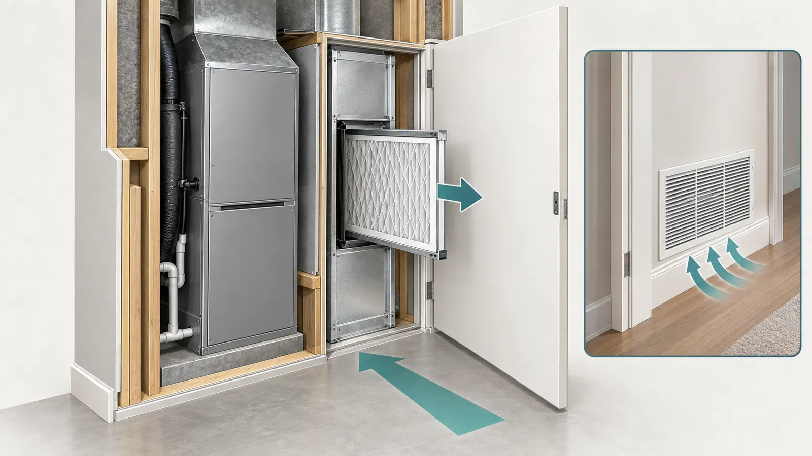
DOE gives different examples for different equipment locations. For an accessible utility-room air handler, a filter media box can be located at the return plenum. For attic equipment, the guidance describes a staircase or pulldown stairs and a permanently installed walkway, along with a filter media box with a gasketed removable access panel. Where equipment is inaccessible, the guidance points to filters at return grilles. These are DOE design examples, not a universal building-code checklist; the DOE access guidance should be checked against the actual layout and the authority having jurisdiction.
Utility room, closet, attic, and crawlspace tradeoffs
Utility room: A central cabinet can be convenient and easy to label. Check whether the room has enough working clearance after the furnace, air handler, condensate equipment, water heater, electrical panel, and storage are installed. A good drawing showing the cabinet does not prove the finished door will open.
Closet: A cabinet inside a closet may save visual space but can become a service conflict. Record the door width, opening direction, shelves, and whether the filter can be slid out while the closet door remains open. If the air handler is in a bedroom or hallway closet, ask how noise, dust, and routine service are handled.
Attic: The issue is not merely distance. It is safe approach, lighting, walking surface, hatch size, and the ability to carry the media. Do not ask a homeowner to use roof framing, loose insulation, or a ceiling joist as a maintenance platform. Have the builder and HVAC professional resolve the access provision in the construction documents.
Crawlspace: A deep cabinet may be physically reachable but still impractical if the route involves low clearance, mud, sharp metal, standing water, or contaminated material. A return grille in a finished room may be more serviceable, but it introduces its own grille-area, appearance, and air-distribution coordination questions.
Treat nominal size, actual size, and cabinet size separately
The filter name may be “16 by 25,” while the actual media and the cabinet opening are different. The Aprilaire 1410 example lists nominal 16 by 25 dimensions and actual cabinet dimensions of 17.75 inches high × 6.75 inches wide × 30.167 inches deep, along with specified 410, 413, and 416 media compatibility. The 30.167-inch value is the cabinet depth in this product listing; the 6.75-inch value is its width, not its depth. A homeowner comparing generic 4-inch media to that unit should not assume the filter rails, seals, thickness, or replacement warranty are interchangeable. See the manufacturer’s model-specific 1410 specifications.
Ask for a dimensioned submittal that shows:
- The cabinet’s actual outside height, width, and depth.
- The duct connection opening and any transition required.
- The filter slot or rail dimensions.
- The door or access-panel dimensions.
- The direction of airflow.
- The nominal filter size and compatible media models.
- The space required to remove the media fully.
- The seal or gasket location.
If the cabinet is field-modified, require the installer to state who approved the modification and how compatibility, sealing, and warranty conditions are preserved. Do not cut or fold media to make a mismatch fit. A filter that bows, gaps, bypasses, or gets sucked into the duct is not an acceptable substitute.
Set a maintenance interval that can survive real life
The correct interval is based on the selected media’s instructions and the home’s operating conditions. ENERGY STAR advises homeowners to check a central HVAC filter monthly, change it when dirty, and change it at least every three months; it warns that a dirty filter can slow airflow, waste energy, damage equipment, and contribute to early failure. Read the ENERGY STAR filter-maintenance guidance, but do not copy its general minimum over a more specific equipment instruction.
For one manufacturer’s deep-media system, Aprilaire says replacement frequency varies with operating time, people and activities, carpeting, pets, home size, smoking, and local pollution; its manual recommends annual replacement for the listed media air cleaners, while noting that media may last up to two years when the blower is not run continuously and that larger continuously operated systems need more frequent attention. That is a model-specific instruction, not proof that every 4-inch media lasts a year. See the Aprilaire owner manual’s maintenance section.
Write the interval in two forms:
- Calendar check: for example, inspect monthly during the first season and record what you observe.
- Change trigger: the manufacturer’s interval, a pressure-drop trigger if the system supports one, visible loading, an alarm, an air-quality event, construction dust, wildfire smoke, or another documented condition.
Do not use a visual inspection as a substitute for a measured pressure limit when the equipment documentation provides one. A filter may look acceptable and still be restrictive, or look dusty without exceeding the system’s change criterion. Conversely, do not stretch a manufacturer’s annual instruction because a filter “still looks clean” when it has been exposed to unusual construction dust or smoke.
Make replacement media part of the handover
At handover, the owner should receive the cabinet model, media model, nominal and actual dimensions, airflow direction, replacement procedure, normal access route, first inspection date, and a dated source for replacement media. Take a photograph of the label inside the door or on the cabinet. Store one spare only if the manufacturer’s packaging and the home’s storage conditions support it.
The Aprilaire manual illustrates why this record matters: it maps the 1410 and 1610 models to 410 or 413 replacement media, describes the outlet-side orientation, and directs the owner to the model number on the label inside the door. It also states warranty conditions tied to qualified installation and prescribed maintenance. Those conditions belong to Aprilaire’s product; other manufacturers may use different media, orientation, and warranty terms. Review the manual’s replacement-media and warranty instructions for the exact model, and keep your own installed record.
Before closing the return, your next decision is whether the access route has been physically proven. Have the installer demonstrate full media removal with the planned cabinet, not just point to the location on a drawing. If the demonstration cannot happen because the area is not yet built, mark the access as an open construction checkpoint with an owner and a date.
Sequence the decision across design, rough-in, and handover #
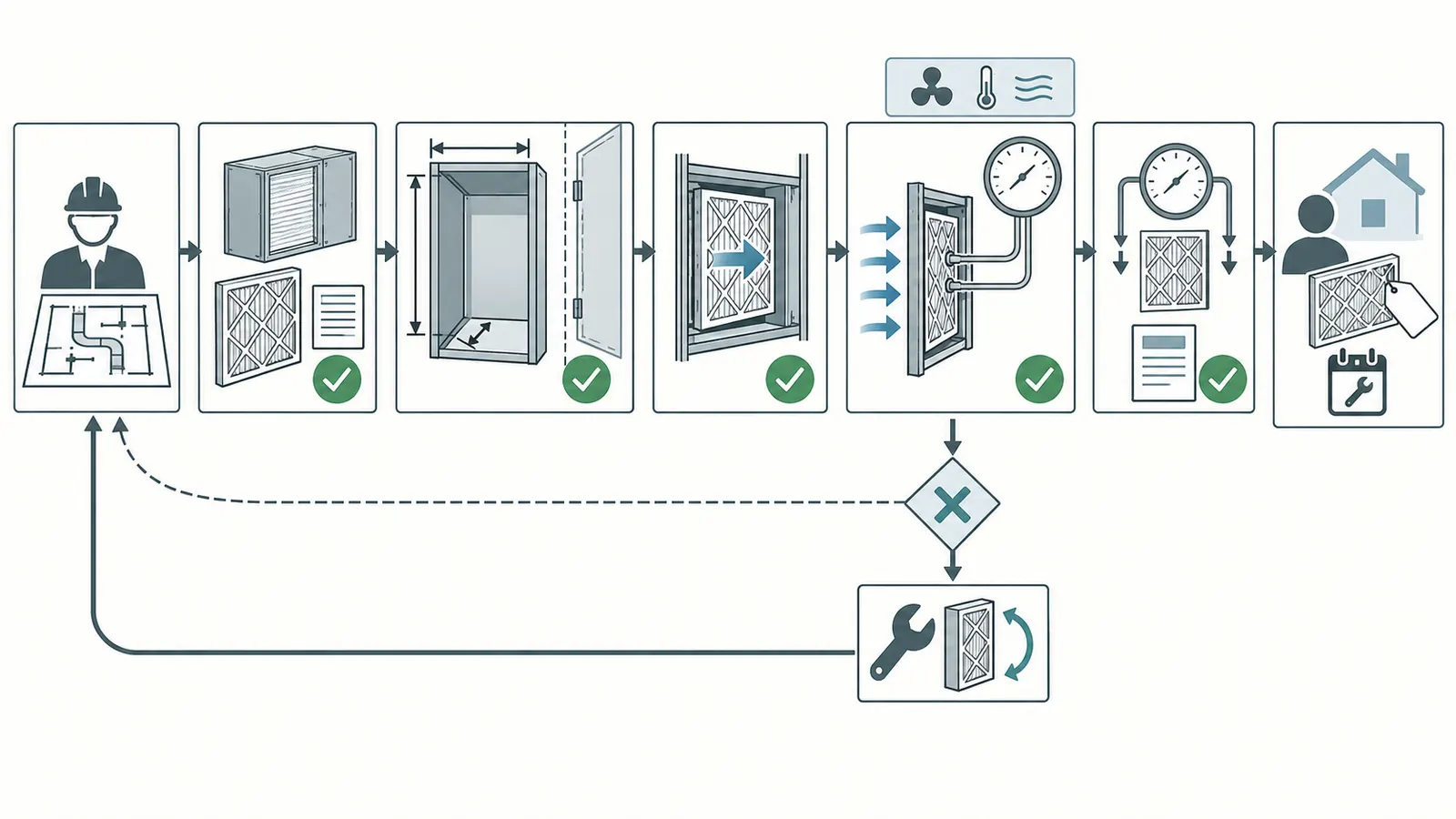
The filter cabinet should be selected before the return-air layout is frozen, checked again before rough-in is closed, and recorded again at commissioning and handover. Each participant has a different responsibility, so the sequence should create explicit handoffs rather than one final request to “check the filter.”
Step 1: homeowner writes the operating brief
Start with the household’s actual decision, not a product. Record who will change filters, whether anyone will have access limitations, whether the home has pets, construction-dust exposure, seasonal smoke, or another reason to consider a particular efficiency claim, and whether the owner prefers a central cabinet or accessible return grilles. Do not turn an allergy or respiratory concern into a guaranteed health outcome. Record the concern as a design input for the HVAC professional and appropriate health guidance.
Also record the acceptable ownership pattern. Some homeowners prefer a low-frequency deep-media replacement if the exact media is readily available. Others prefer common 1-inch filters that can be purchased locally. Either preference can be reasonable when the system is designed for it. The choice should reflect actual maintenance behavior, not a salesperson’s statement that one depth is universally superior.
Step 2: HVAC designer identifies equipment and airflow
The designer or contractor identifies the equipment model, the design airflow for the relevant modes, the blower information, and the external-static-pressure criterion with its measurement boundary. The designer should list the return path, coil, cabinet, grilles, transitions, ducts, dampers, and any other known components, then mark which losses are already represented in the equipment data and which must be added once to the component budget. Ask for the filter’s share of the criterion, not just a system total with an undefined boundary.
If the equipment is not selected, the cabinet choice is provisional. A cabinet built around one air handler may have a different connection, airflow, or fan limitation than another. Put the equipment decision ahead of the final pressure comparison, or clearly state the range of models the cabinet is intended to support.
Step 3: supplier provides the complete candidate submittal
The cabinet or filter supplier provides exact models, dimensions, compatible media, pressure-drop curves or points, and installation requirements. Ask the supplier to state whether pressure data are for clean media, loaded media, a defined dust-loading test, or a change-out criterion. Ask whether a MERV or other claim is certified, tested, or simply a marketing description, and what that claim applies to.
Do not treat a supplier’s claim that a deeper filter “reduces pressure drop” as the final answer. DOE’s research summary supports the surface-area mechanism and reports that pressure behavior varied among tested filters and operating conditions. The supplier must connect the general mechanism to its exact model. Use the DOE source-comparison discussion as the reason to request actual data.
Step 4: builder coordinates the space and access
The builder overlays the cabinet and removal path on the architectural, mechanical, framing, electrical, and plumbing plans. Confirm that the cabinet does not conflict with structural members, fire-separation assemblies, insulation, refrigerant lines, condensate piping, electrical disconnects, combustion venting, or other service clearances. Do not ask the homeowner to resolve these conflicts in the field.
The builder also coordinates any attic walkway, hatch, platform, closet door, access panel, grille opening, or finish trim. If a return grille is the maintenance location, the grille and filter must be the specified size and must remain accessible after furniture and built-ins are installed. If multiple grilles share the filter duty, the drawings should identify the intended filter arrangement and airflow strategy.
Step 5: installer verifies before closing the return
Before insulation, drywall, ceiling finishes, or fixed cabinetry close the path, the installer verifies the actual cabinet, filter, door, gasket, airflow arrow, support, transition, and access. Photograph the installation with the model label visible. Record substitutions. If the installed cabinet is not the approved submittal, stop the handoff and repeat the pressure, fit, and access comparison.
The installer should not rely on a generic filter temporarily placed in the slot if the final media has different dimensions or pressure data. A temporary construction filter may protect the equipment during construction, but it does not prove the final design. Ask which filter is being used for construction, when it will be replaced, and how construction dust will be considered in the first maintenance interval.
Step 6: commissioning technician measures the installed system
Commissioning occurs with the final equipment, filter, grilles, dampers, and operating mode that the test is intended to represent. The technician records airflow, static pressure, filter pressure drop if measured separately, fan setting, and relevant conditions. The contractor should also evaluate airflow after duct work or other repairs; ENERGY STAR explicitly recommends this type of post-work airflow evaluation and says the contractor should include a new filter in duct-improvement work. See ENERGY STAR’s duct-improvement contractor guidance.
An airflow reading with the wrong filter, an open cabinet door, a bypassed grille, or a temporary blower setting is not the final handoff. The record must state what was installed and how the reading was taken. If the system cannot meet the design airflow or the measured pressure is outside the documented criterion, the next action belongs to the HVAC professional: diagnose the system, correct the installation or design, and repeat the verification.
Step 7: owner receives the operating record
The owner receives the final model numbers, filter part number, installation date, access instructions, orientation, first inspection date, pressure and airflow readings, and unresolved items. If a maintenance interval depends on a pressure sensor or controller, explain what the device measures and what does not trigger it. If the installer recommends annual replacement, state whether that recommendation came from the manual, a measured condition, or a project-specific plan.
The next decision is not “which brand should I buy later?” It is whether the installed system can be operated and maintained using the record. If the owner cannot tell which side of the filter faces the blower, which model replaces it, or whether the door can be opened safely, the handover is incomplete.
Jurisdiction and program limits
This guide uses the United States as the default market, but a U.S. homeowner still has to identify the actual jurisdiction for local rules. The relevant authority may be a city, county, state, tribal, or other building department, depending on the project. Energy-program requirements may come from a state program, utility, HERS rating, ENERGY STAR pathway, or another administrator. Ask the authority having jurisdiction or the program administrator for the current requirement that applies to your project and date.
Do not describe California Title 24 as a national filter rule. The DOE account is a 2014 historical summary and is useful for understanding the research and design logic, but it cannot establish what a current California project or a project in Texas, New York, Colorado, Florida, or any other jurisdiction must do. For California, use the current CEC 2025 Energy Code page and current Title 24, Part 6 filter text, then confirm applicability with the actual authority having jurisdiction.
ENERGY STAR guidance is a voluntary program resource, not a substitute for a building permit, mechanical code, equipment listing, or local inspection. Manufacturer manuals are product instructions, not universal code. Record which source controls each requirement in the worksheet.
Verify the installed choice before rough-in closes and again at commissioning #
Accept the cabinet only when the installed equipment, filter, airflow, pressure, access, and records match the approved comparison. A remote review of plans or photographs cannot sign off airflow, static pressure, sealing, fire separation, or safe access. Those site-specific checks belong to the qualified HVAC, building, and commissioning professionals responsible for the work.
What the homeowner can safely verify
You can safely collect records and observe the work without opening a moving air handler or entering an unsafe attic or crawlspace. Ask to see:
- The exact HVAC equipment model and approved submittal.
- The exact cabinet and media model.
- Nominal and actual filter dimensions.
- The airflow arrow and the written replacement direction.
- The door, grille, gasket, rail, or access-panel detail.
- The pressure-drop data’s airflow and filter condition.
- The design airflow and external-static-pressure criterion.
- The measured commissioning result and test operating mode.
- The date of the first filter check and the change trigger.
- The local authority or energy-program requirement, if one applies.
Take photographs of labels and access locations. Keep them with the homeowner manual, warranty, equipment schedule, and commissioning record. If a claim is based on a local requirement, write the jurisdiction next to it. If a claim is based on the manufacturer’s instruction, write the product model next to it.
What a qualified professional should measure
The HVAC or commissioning professional should choose appropriate instruments and procedures for the equipment and project. Ask for a record that identifies:
- The operating mode and fan setting.
- The final filter installed during the test.
- The measured or calculated airflow and units.
- Static pressure measurement locations and values.
- Filter pressure drop, if measured separately, with upstream and downstream locations.
- The condition of dampers, grilles, doors, and access panels.
- The return and supply configuration at the time of the test.
- Any limitation that prevented a complete measurement.
- The corrective action if the result did not meet the design criterion.
- The person responsible for the next verification.
Do not put your hand into a blower compartment, remove an energized panel, open electrical equipment, or reach around moving fan components to check a filter. Turn equipment off only in accordance with the manufacturer’s instructions and only for routine owner-accessible filter service. For a product-specific example, Aprilaire tells owners to set the thermostat mode to off and fan to auto before removing the air-cleaner door; it also describes contractor installation of the unit. Read the Aprilaire owner manual for that product, and use the selected equipment’s manual for your system.
Commissioning acceptance table
| Checkpoint | Evidence to collect | If it fails |
|---|---|---|
| Equipment identity | Model and configuration match the approved design | HVAC designer redoes compatibility review |
| Cabinet identity | Model, dimensions, connection, and filter rail match submittal | Installer corrects or documents an approved substitution |
| Filter identity | Exact media part number, size, orientation, and efficiency claim | Do not accept a generic substitute without new pressure and fit data |
| Access | Door or grille opens fully from a safe, finished route | Builder and installer resolve the obstruction before close-up |
| Seal and support | Gasket, rails, cabinet, and transition are intact and supported | Installer corrects bypass, gaps, vibration, or deformation |
| Airflow | Measured or documented at the specified operating condition | Qualified HVAC professional diagnoses duct, fan, coil, damper, or filter issue |
| Static pressure | Measurement locations, units, and results are recorded | Compare with equipment/design limit; do not solve by guessing a MERV |
| Maintenance handoff | Interval, trigger, part number, and disposal path are written | Handover remains open |
| Local compliance | Applicable jurisdiction and program requirement are identified | Ask authority or program administrator; do not generalize another state’s rule |
What a failed measurement does and does not mean
If airflow is low, do not conclude that the cabinet is the only cause. Check the filter orientation, collapsed or restrictive media, cabinet bypass, return grilles, dampers, duct size, crushed flex, coil condition, blower setting, and other design components through the responsible professional. ENERGY STAR’s guidance says many return ducts are too small and recommends evaluating supply and return balance and airflow after duct work. That supports a system diagnosis, not a one-product blame assignment. See ENERGY STAR’s supply-and-return and post-work airflow guidance.
If static pressure is high but airflow appears acceptable, do not assume the ECM has solved the problem. The fan may be using more power or operating near its allowable range. If airflow is acceptable but the cabinet leaks around the filter, the equipment may be drawing unfiltered air and the pressure comparison is incomplete. If the pressure is acceptable with a clean filter but not at the documented replacement condition, the maintenance plan is not compatible with the design.
If the contractor says the reading is “normal,” ask which design value makes it normal, where the measurement was taken, what filter condition was installed, and what the equipment manufacturer allows. A verbal reassurance is not the same as a record.
Construction and close-up checkpoints
Use the following hold points in the construction schedule:
- Before equipment order: exact equipment family, anticipated airflow range, and cabinet concept identified.
- Before mechanical submittal approval: exact cabinet, compatible media, dimensions, pressure data, and access drawing attached.
- Before framing or rough-in close: cabinet location and removal path checked against actual framing, utilities, and finish plans.
- Before insulation or drywall: cabinet support, transition, gasket, filter orientation, and access panel are visible and photographed.
- Before startup: final filter and operating configuration identified; construction filter status recorded.
- At commissioning: airflow, static pressure, and any separate filter-drop measurement recorded under stated conditions.
- At handover: owner receives media part number, maintenance plan, labels, records, and the next check date.
These checkpoints prevent a common failure: a deep cabinet appears on the mechanical plan but a shallow opening is installed, or a central filter location is shown but a wall, shelf, or duct makes replacement impossible. The earlier the mismatch is found, the less likely it is to require finished-wall demolition or an undocumented field modification.
Your next decision is whether the commissioning record is complete enough to establish a baseline. If not, keep the design decision open and assign the missing measurement or document.
Diagnose failure cases and make the next decision #
When a cabinet comparison goes wrong, separate the observed symptom from the unproven cause, then assign the safest next action to the responsible professional. A filter that looks dirty, a noisy return, or a low airflow complaint is a prompt for diagnosis—not proof that a deeper cabinet, lower MERV, or larger blower is the answer.
Failure matrix
| What you observe | What it may indicate | What you must not infer | Safest next action |
|---|---|---|---|
| The 1-inch filter is visibly loaded soon after move-in | Construction dust, high particle load, small face area, poor sealing, or an interval that is too long | That all 1-inch filters are unsuitable or that a 4-inch unit will automatically solve it | Check the media, access, return leakage, operating conditions, and pressure with the HVAC professional; shorten the initial inspection interval |
| The 4-inch filter has low published clean drop | More media area or a different media construction may help | That the whole system will have low pressure or that the loaded value is also low | Add clean and change-condition data to the pressure budget and commission the installed system |
| The filter door will not open after finishes | Cabinet conflict, insufficient removal clearance, or an access plan that was never built | That a smaller filter can be folded or forced into place | Stop close-up or request a builder/installer correction; do not modify the media as a workaround |
| Filter bows, collapses, or is pulled into the duct | Undersized filter, unsupported media, excessive pressure, incorrect fit, or bypass | That a stronger filter alone is the right correction | Turn the system off if safe, keep people away from moving components, and have a qualified HVAC professional diagnose the installation |
| The installer cannot provide pressure-drop data | Supplier documentation gap or a candidate chosen by label | That MERV predicts the drop closely enough | Mark the candidate unresolved and request exact model data or a documented design/commissioning method |
| Airflow is low after a filter change | Filter resistance, orientation, duct, coil, damper, blower setting, or measurement issue | That the new MERV number alone caused the result | Have the professional check the full return and supply system and compare with the baseline |
| Fan noise increases after installing the final media | Increased resistance, return restriction, leakage, or a control response | That noise proves the cabinet is defective | Record the filter model and operating mode; request static-pressure and airflow diagnosis |
| The filter looks clean but the home is dusty | Bypass, leakage, inadequate return, outdoor infiltration, construction residue, or source control issue | That a higher MERV or deeper media will fix all dust | Inspect sealing, ducts, returns, and pollutant sources; do not promise an indoor-air-quality outcome from MERV alone |
| Replacement media is unavailable | Proprietary part, discontinued model, local supply issue, or wrong part record | That a similar nominal-size filter is interchangeable | Contact the manufacturer or installer and recheck fit, efficiency, pressure, and warranty before substituting |
| An annual change recommendation conflicts with visible loading | Different operating time, dust load, blower schedule, or product-specific instruction | That either the calendar or appearance is universally correct | Follow the selected manual and ask for a condition-based maintenance plan or pressure criterion |
| California code language appears in a non-California proposal | Source scope has been copied without jurisdiction | That Title 24 applies nationally | Identify the actual authority and energy-program administrator for the project |
A 1-inch candidate that should be reconsidered
Reconsider the 1-inch concept when the exact media’s change-condition pressure drop consumes the available filter budget, the return face is too small for the design airflow, the equipment manufacturer’s allowable resistance is exceeded, or the filter cannot be reached safely. Also reconsider it when the planned efficiency claim is not available in a compatible low-resistance construction and the household’s stated requirement cannot be met without an unverified substitution.
The next move is not automatically “install 4 inches.” The designer may solve the same problem with a larger face, multiple return grilles, a different media construction, a redesigned transition, or an equipment and duct arrangement with more suitable capacity. The DOE profile names larger dimensions, deeper pleats, and multiple return filters as ways to increase surface area. Choose among them using the complete pressure and access record, not a depth slogan. See DOE’s surface-area comparison.
A 4-inch candidate that should be reconsidered
Reconsider the 4-inch concept when it creates an access conflict, requires a transition that was not included in the pressure budget, relies on a proprietary media that the owner cannot obtain, lacks loaded pressure data, or is being used to justify a higher efficiency claim that the equipment cannot support. Reconsider it when the installer has to alter the cabinet or filter slot without an approved design and documented warranty review.
Depth is not a substitute for a return-air design. A narrow 4-inch slot can still be restrictive. A cabinet can have a large internal media area while its exterior connection or upstream grille is small. A replacement interval can be long only when the product instructions and operating conditions support it. A “whole-house air cleaner” product is not a universal answer for every furnace, air handler, heat pump, or return configuration.
Safety boundary for this decision
This is a moderate-safety home-building decision because it involves moving air, electrical equipment, sharp sheet metal, elevated attic or crawlspace access, and potentially combustion appliances or condensate systems. A homeowner can record model numbers, ask for submittals, photograph an accessible label, and observe a finished access demonstration. Assign equipment selection, duct modifications, static-pressure and airflow measurements, electrical work, cabinet fabrication, combustion-safety evaluation, and work in unsafe attic or crawlspace conditions to qualified professionals.
Never remove an energized HVAC access panel, reach into a moving blower, stand on loose attic insulation, cut framing or ductwork without the responsible professional, or bypass a safety device to test a filter. If gas- or oil-burning equipment is present, do not assume a duct change is harmless; ask the responsible contractor to address combustion safety. ENERGY STAR warns that duct improvement work should include attention to backdrafting and combustion safety where applicable. Review ENERGY STAR’s professional duct-work guidance and the equipment manufacturer’s safety instructions.
The remote-assessment limit is important: a page, drawing, photograph, or homeowner measurement cannot verify actual pressure drop, airflow, duct leakage, fire separation, combustion safety, or local code compliance. It can help you collect inputs and catch missing handoffs. The qualified local professional and the authority having jurisdiction make the site-specific determination.
The final decision rule
Select the 1-inch cabinet when the exact filter and face area meet the equipment’s pressure and airflow criteria in clean and planned change conditions, the return path is properly designed, and the homeowner can maintain it safely. Select the 4-inch cabinet when its deeper media provides a documented pressure and maintenance advantage that fits the equipment, space, access, replacement supply, and budget. Select neither yet when a material input is missing.
Before the rough-in is closed, ask for one signed or otherwise attributable project record containing:
- Equipment model and design airflow.
- Cabinet model, actual dimensions, and filter connection.
- Media part number, nominal size, depth, efficiency claim, and orientation.
- Clean and change-condition pressure-drop data at stated airflow.
- Equipment pressure limit, other component drops, and the documented filter budget.
- Access drawing or installed demonstration.
- Commissioning airflow and static-pressure results.
- Maintenance interval, change trigger, replacement source, and owner handoff.
- Jurisdiction-specific code or program item, identified by the actual jurisdiction.
If the record is complete and the measured result matches the design, the depth choice is ready to move from design into ownership. If it is incomplete, the next decision is to keep the cabinet unresolved and return the question to the HVAC designer, installer, builder, or local authority who owns the missing fact. That pause is cheaper than closing an inaccessible return or operating a new home with an unverified airflow restriction.
After move-in, check the filter at the interval in the manual and the initial maintenance plan, record what you see, and keep the first replacement date. ENERGY STAR’s general advice to check monthly and change at least every three months is a useful starting point for many central systems, while the selected manufacturer’s instructions and observed operating conditions determine the project-specific routine. Revisit the worksheet after unusual construction dust, wildfire smoke, a major duct change, an equipment replacement, or a repeated airflow or noise complaint. The comparison is complete only when the owner can identify the filter, reach it safely, and show the record that proves the installed system was checked.
Cite this guide
Brictale. “How to Compare 1-Inch and 4-Inch HVAC Filter Cabinets Before a New-Home Design Freeze.” Published 2026-09-28; updated 2026-09-28.
https://brictale.com/build/materials/compare-hvac-filter-cabinet-depth-before-new-home-design-freeze · Read the Markdown version
Original contribution: Filter-cabinet comparison worksheet. A reproducible worksheet for comparing depth, face area, pressure drop, access, cost, and commissioning.
Sources and scope
Evidence behind this page
- For ducted heating and cooling systems, filters are installed on the return side to protect the HVAC motor and improve indoor air quality; the filter should be located where the homeowner can access it for replacement or cleaning.
HVAC Proper Installation of Filters
U.S. Department of Energy Building Science Education guidance for residential ducted HVAC filter location and maintenance access; it does not select a cabinet for a specific equipment model.
Accessed · Link to this claim - DOE guidance gives different access provisions for accessible equipment rooms, attic equipment, and inaccessible crawlspaces or attics, including a removable gasketed media-box panel, a permanent attic walkway, or filters at return grilles where appropriate.
HVAC Proper Installation of Filters
U.S. Department of Energy Building Science Education examples; these are design guidance, not a universal building-code requirement.
Accessed · Link to this claim - The DOE Building America profile describes a historical rule-of-thumb that many residential HVAC systems operate efficiently when total system pressure drop, including the filter and other components, is no higher than about 0.4 or 0.5 inches of water column; that total-system context is not the same accounting boundary as an equipment fan-table or external-static-pressure criterion, and the selected equipment and design govern the allowable value.
DOE summary of 2014 Building America research and California code context; the pressure figures are historical general context, not a national code limit, an equipment fan-table value, or a substitute for defining measurement boundaries and included components in the selected design.
Accessed · Link to this claim - The DOE Building America profile states that filter pressure drop can be reduced by increasing filter surface area with larger dimensions, deeper pleats, or multiple return-air filter locations; it gives the example that a 4-inch pleat has twice the surface area of a 2-inch pleat.
DOE summary of tested filter-sizing research; the statement describes a surface-area mechanism and does not guarantee a pressure drop for every 4-inch product.
Accessed · Link to this claim - The Building America research described by DOE measured pressure drop at multiple face velocities for filters from different manufacturers and considered both PSC and ECM fan motors, producing performance curves rather than treating MERV as the only input.
DOE report of the ARBI filter research; the tested sample is not a universal catalog of current products.
Accessed · Link to this claim - In the DOE-reported tests, 13 filters from different manufacturers were compared with one MERV 2 fiberglass filter at multiple face velocities using PSC and ECM motors; new MERV 8 filters had 2.7 to 4.7 times the pressure drop of the fiberglass reference, clean MERV 8 filters reduced PSC airflow by about 7%, and regulated-airflow ECM fan power increased about 9% on average relative to that reference.
DOE summary of ARBI testing of 13 filters from different manufacturers, with MERV 6-13 filters compared with one MERV 2 fiberglass filter at multiple face velocities and with both PSC and ECM motor responses; the reported 7% PSC airflow and 9% ECM power results are sample- and condition-specific, not predictions for a selected new-home system.
Accessed · Link to this claim - The DOE Building America profile is a November 2014 historical summary that describes the California Title 24 context reported at that time, including filter-resistance, airflow, fan-watt-draw, and equipment-label concepts; it does not establish the requirements for a current California project.
Historical California Title 24 context as summarized by a 2014 DOE profile; use only as background and check the current California Energy Commission code, the permit date, project type, compliance path, and authority having jurisdiction for a live project.
Accessed · Link to this claim - The California Energy Commission says buildings whose permit applications are submitted on or after January 1, 2026, must comply with California's 2025 Energy Code, including the applicable residential provisions of California Code of Regulations Title 24, Part 6.
2025 Building Energy Efficiency Standards
Current California Energy Commission program page; it establishes the 2025 Energy Code version and effective permit-date scope, but the authority having jurisdiction and project compliance documents control the site-specific determination.
Accessed · Link to this claim - For the 2025 California Energy Code's single-family residential provisions, the restructured California Code of Regulations Title 24, Part 6 text identifies Section 402.2.6.12 and its subsections for system air-filter sizing, service accessibility, permanent labeling of design airflow and maximum allowable clean-filter pressure drop, bypass prevention, efficiency, and clean-filter pressure drop; the bracketed cross-references identify the corresponding Section 150.0(m)12 provisions.
Restructured 2025 Energy Code — California Code of Regulations, Title 24, Part 6
California Energy Commission's restructured 2025 Title 24, Part 6 presentation for single-family residential Section 402.2.6.12; California-specific and shown for information, so verify the adopted text, project applicability, compliance path, and local enforcement with the authority having jurisdiction.
Accessed · Link to this claim - Aprilaire lists its 1410 whole-house air purifier with a nominal 16 by 25 inch filter, actual cabinet measurements of 17.75 inches high by 6.75 inches wide by 30.167 inches deep, a supplied MERV 11 410 filter, and compatibility with specified 413 and 416 media; the manufacturer's dimensions are model-specific.
Aprilaire 1410 Whole-House Air Purifier
Current Aprilaire product page for one manufacturer and model; it is an example of why nominal filter size and actual cabinet dimensions must both be recorded.
Accessed · Link to this claim - The Aprilaire owner manual describes the whole-house air cleaner as a component installed by a heating and air-conditioning contractor and says the thermostat mode should be off and the fan set to auto before removing the door.
Aprilaire Media Air Cleaners Models 1210, 1310, 1410, 1510 & 1610 Owner's Manual
Aprilaire owner instructions for the listed media-air-cleaner models; local licensing and installation requirements can differ by jurisdiction.
Accessed · Link to this claim - The Aprilaire manual says replacement frequency varies with operating time and particle generation, recommends annual media replacement, says media may last up to two years without continuous blower operation, and calls for more frequent attention for larger systems operated continuously.
Aprilaire Media Air Cleaners Models 1210, 1310, 1410, 1510 & 1610 Owner's Manual
Aprilaire guidance for its listed models and media; it is not a universal interval for every 4-inch cabinet or filter.
Accessed · Link to this claim - The Aprilaire manual directs owners to use the replacement media specified for the unit, install it in the proper orientation, and notes that its warranty conditions include qualified contractor installation and prescribed maintenance; those conditions apply to that manufacturer's product.
Aprilaire Media Air Cleaners Models 1210, 1310, 1410, 1510 & 1610 Owner's Manual
Aprilaire owner manual and warranty language; do not generalize it to other brands or infer that a MERV label proves interchangeability.
Accessed · Link to this claim - ENERGY STAR advises checking a central-air or heat-pump filter monthly, changing it when dirty, and changing it at least every three months; it warns that a dirty filter can slow airflow, waste energy, damage equipment, and contribute to early failure.
ENERGY STAR homeowner maintenance guidance for heating and cooling systems; the exact interval still depends on the equipment, filter, operating conditions, and manufacturer instructions.
Accessed · Link to this claim - ENERGY STAR says a duct-improvement contractor should evaluate supply and return balance, include a new filter as part of duct improvement, and evaluate airflow after repairs are completed.
Hire a Professional Contractor for Duct Improvement Projects
ENERGY STAR guidance about duct-improvement projects; it supports a verification handoff but does not set a universal airflow target for a specific new home.
Accessed · Link to this claim - ENERGY STAR states that new heating and cooling equipment must be properly installed for best performance and directs homeowners to ask about proper installation rather than treating equipment selection alone as the outcome.
ENERGY STAR homeowner guidance; the page's general performance statement is not a guarantee for any particular system or installer.
Accessed · Link to this claim