How to Compare Heat Pump Water Heater Locations and Electrical Options Before Rough-In
Compare HPWH rooms, airflow, condensate, service access, water-pipe distance and electrical capacity before rough-in with a model-first worksheet.
The short answer
Choose the location only after the exact model manual, room volume and temperature, airflow and service clearances, condensate route, leak protection, water-pipe distance, and electrician’s load calculation all have named owners and evidence. A basement, garage, or closet is not automatically suitable. If one input is missing, record a hold and resolve it before rough-in rather than treating a breaker slot or room label as approval.How to Compare Heat Pump Water Heater Locations and Electrical Options Before Rough-In
Choose the location only after the exact model manual, room volume and temperature, airflow and service clearances, condensate route, leak protection, water-pipe distance, and electrician’s load calculation all have named owners and evidence. A basement, garage, or closet is not automatically suitable. If one input is missing, record a hold and resolve it before rough-in rather than treating a breaker slot or room label as approval.
This guide is for a new U.S. home before plumbing and electrical rough-in. The homeowner coordinates the designer, builder, licensed electrician, and qualified plumber. It excludes DIY wiring, remote diagnosis, commercial units, and universal product claims.
This decision belongs in Brictale’s materials journey for building a home, and the Brictale blog is the verified index for the wider planning sequence. Use those internal routes for context; use the named project professionals and authority having jurisdiction for the actual design and approval.
The project jurisdiction matters. No city, county, or state was supplied in the approved brief, so this guide makes no local permit, adopted-code, outlet, pan, drain, disconnect, or inspection claim. For the actual project, write the jurisdiction as the city and state, or county and state where the authority having jurisdiction uses county administration, then have the designer or builder identify the adopted plumbing, mechanical, electrical and energy provisions and the permit path. A manufacturer manual is not a local approval.
Originality brief
Current answers usually explain HPWH efficiency, list product specifications, or isolate one installation constraint in a model manual. The missing decision is a documented, room-by-room choice that connects the exact model, room air, condensate, water piping, electrical capacity, local jurisdiction and trade handoffs before concealed work. This article’s original contribution is the Location-and-Rough-In Comparison Worksheet, checked by reproducing the source-linked inputs and calculations, replacing modeled values with project records, and obtaining dated verification from the named designer, qualified plumber, licensed electrician, builder and AHJ where applicable.
Freeze the decision inputs before anyone draws the rough-in #
Before rough-in, freeze an exact candidate model and jurisdiction record, then compare rooms and electrical configurations against that same evidence. A room name such as “utility room” and a breaker-space count are only starting labels; they do not establish airflow, temperature, condensate, service access, floor capacity, voltage or panel capacity.
The decision is not simply “Where can the tank fit?” It is:
Which candidate location and electrical configuration can be documented as compatible with the selected model, the planned water system, the building, the people who will use the space, and the actual project jurisdiction before concealed work begins?
That wording changes the order of work. You do not pick a favorite room, ask trades to make it fit, and discover after drywall that the heater needs a drain above its condensate outlet or that the selected manual rejects the available voltage. You first create a requirements record, then test each room against it.
The seven inputs that control the comparison
Record these inputs in the worksheet before asking for final rough-in dimensions.
Exact product identity. Record brand, model number, nominal tank size, voltage, manual title, manual revision, publication date if shown, and the URL or file supplied by the manufacturer. “50-gallon hybrid” is not an identity. Two models with the same nominal capacity can differ in room volume, temperature, clearance, condensate and circuit requirements.
Project jurisdiction. Record the property’s city, state and, where relevant, county, plus the AHJ name or permit portal used for the home. The record should say who confirmed the adopted code editions, permit and inspection steps, and any local treatment of drain pans, relief discharge, condensate, electrical protection or equipment location. If the project is not yet assigned a parcel, write “jurisdiction unresolved” and treat the comparison as preliminary.
Candidate-room geometry. Record length, width, unobstructed height, door and louver dimensions, equipment that will occupy the room, the heater’s footprint and height, and every obstruction within the service zone. Use feet for the room-volume calculation and inches for clearances. A plan dimension that includes a future shelf, furnace, stored boxes or framing chase is not free air.
Environmental conditions. Record whether the space is conditioned, the design or observed low and high ambient temperatures, freezing exposure, dust, lint, corrosive vapors, moisture, vehicle exhaust risk and occupant sensitivity to fan or compressor noise. A garage may offer volume but introduce cold, fumes, storage and impact concerns. A closet may be warm and close to fixtures but lack air exchange.
Water and drainage paths. Record the cold-water entry, hot-water route, shutoff location, relief-valve discharge concept, pan protection, condensate outlet height, drain elevation, horizontal run, slope, pump location if needed, and the destination of each discharge. Condensate and temperature-and-pressure relief discharge are not automatically the same line. The final destination and connection method require the plumber and local jurisdiction.
Electrical inputs. Record the utility service voltage, phase, service rating, main panel location, planned large loads, available spaces, subpanel proposal if any, conductor route, disconnect concept and the electrician’s load calculation or written hold. A blank breaker position is not spare capacity. A panel label is not a load calculation. A nominal 200-amp service is not a universal guarantee that every planned load is acceptable.
Responsibility and proof. Every row needs an owner and a verification record. The homeowner can measure accessible dimensions and collect documents. The designer can coordinate the room and chase. The plumber can verify water, drain, pan and relief-discharge coordination. The licensed electrician can design the circuit and evaluate service and panel capacity. The builder can sequence framing, blocking, access and penetrations. The AHJ decides adopted rules and approvals for its jurisdiction.
DOE’s own HPWH field-validation project describes a decision-tool scope that includes panel capacity, water-heater location, size and condensate-drain installation specifics. That is a useful boundary for this comparison: DOE’s HPWH decision-tool scope supports looking at these constraints together rather than treating efficiency as the only decision.
Treat the model manual as a controlled design input
Download the manual that applies to the exact model you expect to buy. Put the file name, revision and retrieval date in the worksheet. Save a copy in the project record because a web page can change and a product page can show a different generation. At purchase, compare the rating plate, carton or submittal with the frozen row. If the model or revision changes, reopen every pass/fail field.
The supplied manuals show why this matters. The A. O. Smith FHPT-50 manual says the unit requires indoor, vertical, level installation, unrestricted airflow and 700 cubic feet; it states a 6-inch minimum at the outlet-side wall, separately shows 6 inches above the unit for filter maintenance, recommends 3 feet from obstructions at the back, left and right for future service, and calls for freeze protection, service access and a floor capable of supporting the filled heater. The supplied Rheem AP23657 Rev 01 manual also discusses location, service, freezing, floor support and airflow, but gives its own confined-space arrangements and clearances. Those are not interchangeable instructions. Compare the exact manual, not a remembered specification from another brand.
Do not turn a manual statement into a national building rule. If an A. O. Smith manual says 240 VAC and not 208 VAC for FHPT-50, that is a product requirement for that model. It does not mean every HPWH rejects 208 VAC. If a manual says a pan must conform to local codes, that does not tell you which pan rule the project jurisdiction adopted. Capture the statement, assign the verification, and keep the scope attached.
Decide what “go” means
Use three statuses rather than a casual yes or no:
| Status | Meaning | Rough-in action |
|---|---|---|
| Pass | The exact manual requirement and project input are documented, and the responsible professional has accepted the item. | Carry the dimension or circuit into coordinated drawings. |
| Hold | A required value, model revision, jurisdiction answer, calculation or professional confirmation is missing. | Do not conceal the related drain, wiring, framing or access. |
| No-go | A known input conflicts with the exact manual, design or professional determination and no approved redesign exists. | Move the unit, change the selected model, or redesign the system before rough-in. |
“Probably fine” is a hold. “The builder has done this before” is not a model-specific verification. “The room is big” is not an airflow check. The status is meant to keep uncertainty visible while there is still time to change the plan.
Measure room volume, temperature, airflow and service access #
Measure usable free-air volume and the complete service envelope for each candidate room. The comparison should show both the arithmetic and the evidence for temperature, airflow and access; a room passes only if the exact manual and the assigned professional accept the result.
ENERGY STAR’s new-construction guide says manufacturers typically require 450 or 700 cubic feet of free air space and ample installation and service space, then directs the reader to the model-specific guide. Its example of an 8-foot by 12-foot room with an 8-foot ceiling is 768 cubic feet before deductions. That guidance is a screening starting point, not a universal acceptance threshold. ENERGY STAR’s room-volume guidance should be read alongside the selected manual.
Calculate free air in cubic feet
Use:
unobstructed room volume (ft³) = usable length (ft) × usable width (ft) × usable height (ft)
Worked illustrative input:
12 ft × 10 ft × 8 ft = 960 ft³
That arithmetic is transparent, but it is not the whole check. If a furnace, shelving, stored materials or another appliance occupies volume, record the model’s definition of free or unoccupied space and subtract or otherwise apply it as the manual requires. The supplied Rheem manual’s unoccupied-space definition explicitly excludes furniture, appliances and other objects that occupy the room. Do not count the volume behind a sealed door or inside a cabinet just because the plan’s outer dimensions include it.
Measure the room after framing or use coordinated framing dimensions, not an early conceptual rectangle. Note sloped ceilings, bulkheads, dropped beams, door swings and access panels. If the tank head or filter needs to be serviced from above, a ceiling obstruction can be a functional failure even when the mathematical volume passes.
The A. O. Smith FHPT-50 manual gives 700 cubic feet and uses an 8-foot ceiling example of 10 feet by 8¾ feet. It also says that a closet or small enclosure needs adequate air exchange. The supplied Rheem manual gives more than 700 ft³ as a no-additional-ventilation example and describes other room and door arrangements, including a reduced-performance range down toward 450 ft³. It says the reduced-performance condition was not evaluated and is not recommended for optimal performance. This difference is useful evidence, not a permission to choose the looser interpretation. If the model changes, the room test changes.
Compare three common room types without relying on the label
Basement utility room. A basement often offers volume, a concrete floor and a nearby floor drain. Those advantages can be offset by a low drain route, difficult access, colder temperatures, mechanical-room conflicts, a long run to distant bathrooms, or a future finished wall that removes service clearance. Record whether the basement is inside the thermal envelope, the coldest expected ambient, the drain elevation and whether the room will later be used for storage. The exact manual may allow the room but the plumber still needs a workable drain and the builder must preserve access.
Attached garage. A garage often provides free air volume and may be near the utility entry. It can also expose the heater and piping to freezing temperatures, vehicle impact, exhaust contamination, dust, storage encroachment and noise near occupied rooms. ENERGY STAR identifies garages as possible locations in some conditions but says climate, manual requirements and local requirements control. Its guide also warns not to run ducts between the garage and the HPWH because exhaust fumes or other contaminants could be brought toward living space. Read the ENERGY STAR location and ducting limits before treating garage volume as an advantage.
Conditioned closet. A closet can shorten hot-water runs and protect the equipment from freezing, but its volume and airflow are frequently the limiting constraints. A closed door can make a large-looking closet functionally small. A louvered door, transfer opening or duct arrangement changes the architectural, acoustic, fire-separation and comfort design; it is not a cosmetic grille added at the end. If the chosen manual says the unit cannot be in a closet unless adequate air exchange is provided, preserve the opening dimensions and routing in the coordinated design.
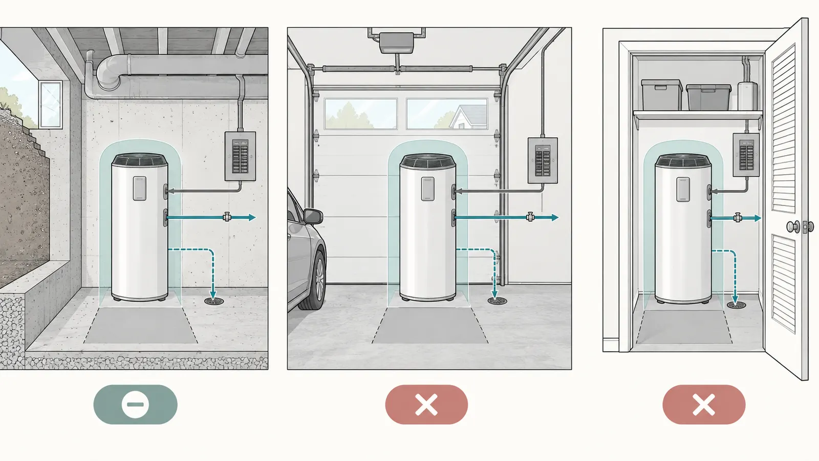
The room comparison should be drawn as a constraint map, not as three tank footprints. Put the same fields beside every candidate: free air, temperature range, intake and exhaust, service envelope, occupied-space sensitivity, floor support, hot-water route, condensate destination, leak protection, electrical record and jurisdiction. A visual comparison is useful only if a missing field remains visible as a hold; it must not turn a large garage or short closet route into an implied approval.
Measure temperature as a design range, not one comfortable afternoon
Record the expected low, typical operating range and high for the space. For a new home, the designer or mechanical professional should establish the expected condition from the building design and climate, while the homeowner can document whether the candidate is conditioned, exposed to the garage or outside air, or adjacent to heat-producing equipment.
For the supplied A. O. Smith FHPT-50 manual, heat-pump operation in Efficiency Mode requires ambient air above 45°F and below 120°F; outside that range the electrical elements activate to meet demand. That does not quantify energy use at your site, and it does not say that a cold garage is automatically unsafe. It does mean a cold-period operating condition must be visible in the comparison. The FHPT-50 manual’s ambient and location requirements are model-specific.
For the supplied Rheem manual, the location section says ambient temperature should not exceed 145°F and separately explains that insufficient air exchange increases energy consumption. The two manuals are enough to show why the room must be compared against the exact model. Do not combine the A. O. Smith 45°F threshold and the Rheem 145°F recommendation into a generalized HPWH operating envelope.
If a garage can reach 38°F during a modeled cold snap, record that as a sensitivity case even if the annual average is milder. Ask the professional to explain whether the selected model can meet the household’s demand in that condition, which operating mode is expected, whether piping and condensate need freeze protection, and what performance or comfort tradeoff is accepted. Do not claim a percentage efficiency penalty unless the exact model’s tested data supports it.
Protect airflow and future access
Airflow has two separate questions: can the heat pump exchange enough air, and where does its cooled exhaust go? A room can have enough volume but still be blocked by a tight closet door, a shelf, a furnace, a dropped ceiling or a future storage plan. A vent can provide an opening but still be poorly located or incorrectly ducted.
ENERGY STAR gives 240 square inches or more of total minimum net-free area as a best practice for passive ventilation, with high and low openings, and describes 130 square inches of net-free area for certain active ducting arrangements. Those are guide values for the described configurations, not a replacement for the exact manual. It warns against ducting only intake or exhaust outdoors because of pressure imbalance, against garage-to-living-space duct paths, and against cold-climate outdoor arrangements that trigger resistance operation or create comfort problems. Use the ENERGY STAR ventilation section to frame the airflow question.
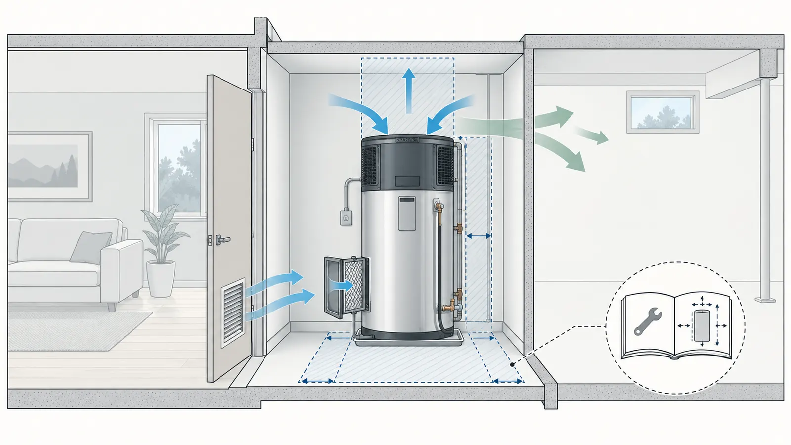
The rough-in drawing should show the unit’s intake and exhaust faces, door or grille net-free area, duct diameter and route if used, transfer-air destination, thermostat location, and maintenance access. A grille’s gross size is not necessarily its net-free area. Have the designer or HVAC professional document the value used. Do not cut a transfer opening in a fire-rated or garage separation without the responsible designer and AHJ resolving the assembly.
Clearance is not leftover floor area. Mark the exact manufacturer minimum around the tank and the larger service envelope requested by the installer. The supplied A. O. Smith manual’s clearance guidance states a 6-inch minimum at the outlet-side wall, separately shows 6 inches above the unit for filter maintenance, and recommends 3 feet from obstructions at the back, left and right for future service considerations. It does not state a 6-inch minimum at the sides and top. The supplied Rheem manual lists 0 inches at the rear and sides and 6 inches at the top in its clearance diagram, but its service and drain access still control the practical arrangement. Use the Rheem manual’s clearance page and the selected model’s current revision rather than copying dimensions across brands.
Treat the room-air sketch and the service envelope as one coordinated drawing. The homeowner can check that the drawing names the exact manual and shows the intended door, grille or duct arrangement, but the designer or HVAC professional must resolve the airflow design and the builder or installer must preserve access after framing and finishes. If the visual field cannot be filled with a measured or documented input, mark the candidate Hold.
Assess noise and cooled exhaust as occupancy constraints
Place the unit where modest fan and compressor sound and cooler exhaust will not be a recurring comfort problem. ENERGY STAR says HPWHs have a fan and compressor, reports that Version 5.0 products emit less than 55 dBA, and notes that some products have 45 dBA sound-pressure ratings. Those are program or product claims, not a promise that sound will be inaudible through your wall. It recommends avoiding locations next to bedrooms and living areas and considering sound insulation. See ENERGY STAR’s sound and cooled-air guidance.
Record the nearest bedroom, office, nursery, living room, television wall and outdoor sitting area. Add a “noise sensitivity” field: low, medium or high, with the reason. A basement behind a closed utility-room door may be more comfortable than a closet beside a bedroom, even if the closet shortens the hot-water route. Conversely, a basement may send vibration through a framing assembly if isolation is not coordinated. The builder and designer should decide whether the floor, wall, or pipe connections need isolation appropriate to the selected product.
Do not use a manufacturer’s brochure sound number as a site measurement. The supplied Rheem ProTerra product literature reports 45 dBA under a stated third-party certified testing condition at 6.28 feet for the covered product literature, while ENERGY STAR discusses a broader program limit and other products. Use the rating for comparison, ask how it was measured, and treat the room assembly and distance as separate design factors.
Compare water piping, condensate and leak protection together #
Choose the candidate that gives the plumber a defensible water, condensate, relief-discharge and leak-protection route with service access; the shortest hot-water path alone is not enough. Condensate is a planned water stream, and the selected model can impose different pipe sizes, slopes, drain elevations, pump controls and freeze measures.
Map every water path before the floor is closed
Draw five separate paths on the plan:
- Cold-water supply into the heater, including shutoff and access.
- Hot-water outlet to the distribution manifold or trunk.
- Temperature-and-pressure relief discharge to its approved destination.
- Condensate primary and overflow paths.
- Drain-pan discharge or leak-detection response, if specified.
Label the pipe size stated by the manual, the elevation at every turn, the horizontal distance, slope direction, termination and access point. Do not merge paths in the drawing just because they are all “water.” The supplied Rheem manual specifically says not to connect T&P plumbing to condensate plumbing and says the condensate should not drain into the water-heater pan. The supplied A. O. Smith manual also calls for independent condensate and relief-discharge arrangements in its condensate guidance.
Pressure-path stop rule. If the temperature-and-pressure relief valve is leaking or discharging, stop the homeowner inspection there: do not cap, plug, obstruct, reset or diagnose the condition remotely. Keep people away from hot discharge, do not merge it with condensate, and contact a qualified plumber or service professional. The supplied A. O. Smith manual says a dripping or leaking relief valve needs a qualified person and warns not to plug or remove the valve. This guide does not authorize testing, resetting or repair of a relief device.
For the project record, write the actual proposed destination: for example, “basement floor drain below outlet at [elevation], subject to plumber and [named jurisdiction] review,” rather than “drain nearby.” If no city, county or state is yet known, write “local discharge rule unresolved.” That is more useful than silently assuming a national rule.
Test gravity before choosing a pump
A gravity route is usually simpler when the drain is genuinely lower, continuously pitched, accessible and permitted for that discharge. ENERGY STAR says condensate lines are based on gravity, should not have a section higher than the discharge port, and may use a pump when gravity drainage is impractical. It lists floor drains, trench drains, mop sinks, hub drains, standpipes, utility sinks and laundry sinks as examples of destinations, while warning against direct discharge to DWV piping or the safety pan. Read the ENERGY STAR condensate guidance.
Do not infer that an available floor drain is acceptable without checking its elevation, connection detail and local requirements. A drain can be near the heater but too high for gravity. A long route can lose its required slope at a doorway or beam. A line hidden in a wall can become impossible to clean or verify. A pump can introduce a power connection, float-switch, overflow and maintenance dependency.
For the supplied Rheem manual, the calculation is explicit:
required vertical fall (in) = horizontal condensate run (ft) × 1/8 in/ft
Illustrative modeled route:
24 ft × 1/8 in/ft = 3 in of minimum fall
That 3-inch result is not a universal condensate slope. It is the value from the supplied Rheem manual’s stated 1/8-inch-per-foot instruction for the covered product. If a different model is selected, replace the source input. The Rheem manual also specifies a 3/4-inch primary connection, says not to reduce below the connection size, calls for a P-trap when connected to a sewer pipe, and gives a 2-gallon-per-day minimum pump capacity when no drain is available. Verify those Rheem-specific condensate inputs in the manual.
For the supplied A. O. Smith FHPT-50 manual, the comparison is different: it describes a 3/4-inch primary condensate line and 1/2-inch overflow, says the lines should terminate no more than 6 inches above an adequate drain, and calls for a pump if a floor drain is unavailable or above the condensate line. It also says condensate lines should be in conditioned areas, with specified protection in freezing areas, and that the pump should shut off the heat pump if the float switch activates. Use the FHPT-50 condensate section for that model.
The source difference changes room ranking. A basement floor drain below the A. O. Smith outlet may pass with a gravity concept. A garage floor drain may be physically lower but still require freeze protection. A conditioned closet with no drain may need a pump and a serviceable route. A room with no acceptable drain, pump location or overflow response is a no-go until redesigned.
Coordinate pan and leak protection without claiming a local rule
A storage tank holds substantial water. The supplied A. O. Smith checklist records 573 pounds for a filled 50-gallon unit, and its location instructions require a floor capable of supporting the filled heater and provisions to protect the area from water damage. The supplied Rheem manual likewise says the floor must support the filled heater and recommends a suitable drain pan where leakage could damage adjacent areas or lower floors. These manual statements support planning for water damage; they do not determine the pan rule for your project.
Have the plumber and designer answer:
- What is the filled weight shown by the exact model manual?
- What floor, platform, curb or blocking supports it, and who verifies that support?
- Is the candidate above finished space, electrical equipment, insulation, stored goods or a lower floor?
- Where does pan water go, and is that destination accepted by the actual jurisdiction?
- Does the selected model include a leak sensor, shutoff or alarm, and what happens if it activates?
- Can the pan, sensor, drain and tank connections be inspected without removing fixed construction?
Do not route HPWH condensate into the safety pan as a shortcut. The pan is for a different failure mode and the supplied manuals and ENERGY STAR guidance distinguish the paths. Do not treat a leak sensor as a substitute for a drain or a drain pan. A sensor may alert or shut a valve, but it does not change the amount of water a failed connection can release before response.
Compare hot-water distance using an actual plan
Locate the heater near the center of the water-piping system or near the greatest demand only after considering the complete plan. The A. O. Smith manual says to select a location near the center of the water-piping system. The supplied Rheem manual says to locate the heater as near as practical to the area of greatest heated-water demand because long uninsulated hot-water lines can waste energy and water. Those are planning directions, not a formula that proves one room is best.
Measure the pipe route, not straight-line distance. Count horizontal and vertical segments, manifold location, recirculation equipment, insulation, penetrations and access. A basement heater may be 15 feet from the kitchen in plan view but 35 feet by the routed path. A closet beside the bathrooms may shorten the route while introducing noise, airflow and service constraints. A garage may sit near the main but require longer hot-water piping to the living spaces.
Use pipe distance as a tradeoff score, not an automatic winner. Give the plumber the measured route and ask for the water-distribution approach, insulation and any recirculation consequences. Avoid claiming a particular wait time or energy loss without a designed flow calculation and product/system assumptions.
Preserve maintenance access as part of the room decision
Make the future maintenance task visible in the plan. The A. O. Smith checklist and maintenance guidance call for access to the drain and controls, tell the operator to inspect areas including the lower drain pan and leaking or damaged water piping, and require power to be disconnected before certain filter and condensate maintenance tasks; it says a qualified person should help if the homeowner lacks the needed skills. The supplied Rheem manual’s maintenance warning includes filter and condensate attention and warns that a blocked condensate path can overflow.
The homeowner should not plan to open live electrical compartments or improvise a repair. The useful preconstruction task is to reserve space, document the shutoff and breaker labels, identify who owns the maintenance, and ensure the access panels can be removed. Ask the builder to show the final access dimension on the drawing, not just the tank outline.
Compare electrical configurations without guessing from the panel #
Treat the electrical option as a model-specific design and load-calculation decision owned by the licensed electrician. Compare voltage, phase, circuit rating, conductor path, overcurrent protection, grounding, disconnect, panel or service capacity, utility requirements and local inspection path; never select an option solely because the panel has an empty slot.
ENERGY STAR says new-construction HPWH electrical requirements are similar to electric resistance tanks, describes 208/240-volt and 30-amp service as a common design point, notes that some 240-volt 15-amp products are available, and directs designers to the manufacturer requirements, NEC guidance and local codes. That is a map of options, not a generic wiring instruction. Use ENERGY STAR’s electrical section as a comparison prompt.
Option A: the exact model’s dedicated 240-volt branch circuit
For the supplied A. O. Smith FHPT-50 manual, the electrical checklist requires a 240 VAC single-phase 30-amp power supply and says not to use 208 VAC. It also requires proper overload protection and grounding, and says wiring must comply with applicable codes or, where no local or state code applies, the current NFPA 70 National Electrical Code. The manual directs a qualified electrician for the electrical work. Read the FHPT-50 electrical requirements.
For the supplied Rheem manual, the exact rating plate supplies the voltage and wattage load, and the manual requires a separate branch circuit with copper conductors, an overcurrent protective device and a suitable disconnecting means provided by a qualified electrician. It says wiring must conform to local codes or the latest NEC. Read the Rheem electrical handoff requirements.
Those statements demonstrate why the manual and rating plate belong in the electrical rough-in package. They do not authorize the homeowner to choose wire size, breaker type, disconnect location or conduit. The electrician must use the adopted rules for the actual project jurisdiction and the actual load and routing conditions.
Option B: a lower-amperage or 120-volt product
A lower-amperage or 120-volt product can be a valid design only if the exact product is selected, its manual and rating plate support the proposed supply, and the electrician confirms the complete design. ENERGY STAR notes that 240-volt HPWHs using 15-amp breakers are available and may suit limited-service or multifamily applications, but also says these products have a smaller resistance element and lower first-hour rating than similarly sized 30-amp HPWHs. That is a product category observation, not a license to reconfigure the FHPT-50 or any other model.
If the reason for the option is limited service capacity, write the reason and tradeoff. Ask for the selected model’s first-hour rating, recovery behavior, operating modes, outlet or hardwire requirement, circuit protection and utility compatibility. Confirm the household demand and the expected cold-room condition. Do not promise that a 120-volt model will deliver the same hot-water recovery or fit the same rough-in as a 240-volt model.
If a salesperson suggests “the electrician can adapt it later,” place the choice on hold. A change in model can alter tank height, clearance, airflow, condensate outlet, filled weight, voltage, circuit route, controls and service access. Reopen the worksheet rather than treating the substitution as cosmetic.
Option C: service upgrade, subpanel or redesign
When the electrician’s load calculation does not support the proposed equipment within the planned service, the choices may include a different model, a service upgrade, a subpanel, load-management controls or a broader redesign. The right choice depends on the whole home’s loads, the utility service, the panelboard, the adopted electrical provisions, routing and cost. This guide cannot calculate or approve any of them remotely.
Ask for a written comparison that states:
- Existing or proposed service voltage, phase and rating.
- The calculated load method and all planned significant loads.
- The HPWH nameplate voltage, wattage or maximum input used.
- The proposed branch-circuit and protection arrangement.
- Conductor route, distance, environmental conditions and raceway or cable assumptions.
- Panel spaces, bus ratings, disconnect and grounding or bonding decisions as applicable.
- Utility, permit and inspection dependencies for the actual jurisdiction.
- What changes if the selected model is replaced by a lower-amperage or different-voltage model.
Do not infer capacity from breaker handle totals. Do not add the HPWH to an existing circuit without the electrician’s design. Do not rely on a “smart” control to make an incompatible nameplate voltage acceptable. Demand response or time-of-use features may influence operation, but they do not erase the equipment’s electrical requirements.
Use a bounded calculation, not a fake load calculation
The worksheet can show arithmetic that clarifies what the nameplate means without pretending to engineer the service. For an illustrative 240-volt, 30-amp branch-circuit label:
nameplate branch-circuit rating proxy = 240 V × 30 A = 7,200 VA
This 7,200 VA is a simple apparent-power product for comparison. It is not the HPWH’s measured operating energy, not a conductor-sizing result, not a dwelling-service calculation and not permission to install a 30-amp breaker. The electrician must use the exact product data and applicable rules.
For an illustrative worksheet entry, write:
| Electrical field | Modeled entry | Interpretation |
|---|---|---|
| Candidate model | A. O. Smith FHPT-50, manual 326880-003 | Must be confirmed against purchase and rating plate. |
| Supply named by manual | 240 VAC, single phase | A model requirement, not a national HPWH rule. |
| Supply named by manual | 30 A | Must be designed and protected by the electrician. |
| Simple comparison product | 240 × 30 = 7,200 VA | Screening arithmetic only; not a service-load result. |
| Electrician’s calculated capacity margin | 42 A, illustrative input | Must be replaced by the electrician’s signed or dated record. |
| Status | Hold until load record and jurisdiction are attached | Do not rough-in from the illustrative values. |
The 42-amp margin is deliberately modeled, not observed. It is included to show how a record should distinguish a professional calculation from an unresolved field. Never present it as a fact about a real home.
Verify performance claims separately from installation fit
An energy factor, UEF, sound rating or first-hour rating is not a location approval. AHRI says its certification programs test and certify HVACR and water-heating equipment against published claims through independent third-party laboratory testing, and its directory lets users search certified performance. Use the AHRI certification program description and AHRI directory to check the exact product and rating where applicable.
The National Laboratory of the Rockies report on five integrated residential HPWHs found that control schemes and design features affected performance across representative U.S. climate operating conditions. That is a reason to verify a product’s tested data and operating envelope, not a reason to promise that a particular basement or garage will achieve a published result. Read the laboratory report abstract.
Keep three columns separate:
- Published or certified product fact: exact source, model and test scope.
- Project input: room dimensions, temperature, drain elevation, pipe route and electrical record.
- Professional decision: accepted design, unresolved exception or redesign.
Combining those columns produces overconfident advice. A certified rating can support product comparison, but it does not certify the basement’s drain. A room measurement can show 960 ft³, but it does not approve the model. An electrician’s capacity calculation can support a circuit design, but it does not establish a plumbing pan requirement.
Use the worksheet and inspect a worked illustrative comparison #
Use one row per candidate room and one column per decision constraint, then choose the row with no unresolved hold after the responsible professionals verify it. The worksheet is the original contribution of this article: a reusable cross-trade record that keeps location, water, air, electrical, responsibility and evidence in one place.
Original contribution: Location-and-Rough-In Comparison Worksheet
Summary. The worksheet compares candidate rooms and electrical configurations against the exact model manual before rough-in. It is designed for a homeowner coordinating a designer, builder, licensed electrician and qualified plumber.
Method. For each candidate, record the exact model and manual revision, calculate unobstructed room volume, map temperature, airflow, clearances, water-pipe distance, condensate elevation and protection, then have the designer, qualified plumber, licensed electrician and builder verify their assigned fields. First, copy the model-specific inputs into a requirements block without generalizing them. Next, attach a dated record to each field, mark every constraint pass, hold or no-go, and reopen the comparison when the model, room, jurisdiction, panel, drain or rough-in drawing changes.
Limitations. The worksheet and example are coordination tools, not an engineering load calculation, code determination, product test, or installation instruction. The example uses modeled inputs and does not prove performance at any site. It does not measure sound, establish structural capacity, interpret an adopted code, or predict energy bills. It cannot turn a missing model manual or local permit answer into a pass, and it does not replace a licensed electrician, qualified plumber, designer, builder or AHJ.
Worksheet fields to copy into the project record
| Field | What to enter | Who verifies | Evidence or record |
|---|---|---|---|
| Candidate ID | Basement, garage, closet or other named room | Homeowner and designer | Plan reference and photo or measurement date |
| Exact product | Brand, model, tank size, voltage and manual revision | Homeowner and builder | Submittal, rating-plate photo, manual URL |
| Jurisdiction | City/state or county/state and AHJ | Builder/designer | Permit portal, written AHJ answer or permit record |
| Room dimensions | Usable length × width × height in ft | Homeowner and designer | Dimensioned plan; field check after framing |
| Free-air result | L × W × H = ___ ft³; list deductions or manual definition | Designer and installer | Calculation and manual page |
| Ambient range | Expected low, typical and high in °F; conditioned/unconditioned | Designer or HVAC professional | Design assumption and climate/site record |
| Airflow | Door, grille, duct, net-free area, exhaust destination | Designer/HVAC professional | Airflow sketch and manual page |
| Service clearance | All minimums and preferred service dimensions in | Builder and installer | Coordinated plan and manual page |
| Noise sensitivity | Nearest occupied rooms and sensitivity reason | Homeowner/designer | Plan note and product data if applicable |
| Floor support | Filled weight and support condition | Designer/qualified professional | Structural or builder verification |
| Hot-water route | Routed length, distribution point, insulation and access | Qualified plumber | Plumbing plan and takeoff |
| Condensate | Outlet, line size, elevation, slope, destination, pump/float | Qualified plumber | Drain sketch and manual page |
| Pan/leak protection | Pan, drain, sensor, shutoff and alarm concept | Qualified plumber/designer | Coordination note; local review |
| Electrical supply | Voltage, phase, circuit, protection, disconnect and route | Licensed electrician | Load calculation, one-line or dated design |
| Panel capacity | Whole-home calculation, not slot count | Licensed electrician | Load calculation and panel schedule |
| Responsible trade | Person or company, not only role | Homeowner/builder | Name, license or company record as appropriate |
| Verification record | Date, document, drawing or site check | Assigned owner | File name, page, photo or written confirmation |
| Unresolved risk | Missing input, exception or future change | Homeowner/builder | Hold log and next decision date |
| Status | Pass, hold or no-go | Homeowner and responsible professionals | Initials/date and decision note |
The worksheet should travel with the rough-in set. If the builder moves the heater six feet to avoid a beam, update room volume only if the enclosure changes, but definitely update clearances, drain elevation, hot-water route, electrical route and access. If a product is substituted, clear the entire row and create a new one rather than editing history.
Worked illustrative example: three rooms and one selected model
The following is a modeled example, not a site survey, product test or professional design. Its purpose is to show the comparison method. It uses the supplied A. O. Smith FHPT-50 manual as the selected-model input because that manual gives explicit room, temperature, condensate and electrical criteria. The actual home must replace every illustrative value with measured or professional records.
Modeled project inputs: a two-story single-family U.S. home; jurisdiction not supplied; three candidate rooms; 8-foot ceilings; a selected A. O. Smith FHPT-50; no claim that the model is the final purchase; a licensed electrician’s capacity result is intentionally left unresolved until the design exists.
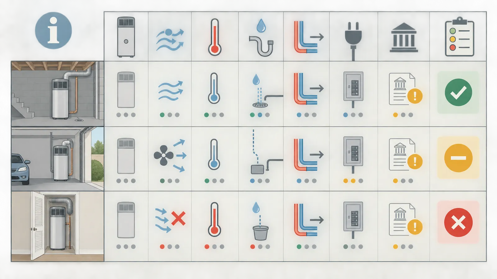
| Candidate | Modeled dimensions and volume | Temperature/air | Water and condensate | Electrical | Initial result |
|---|---|---|---|---|---|
| Basement utility room | 12 ft × 10 ft × 8 ft = 960 ft³ | Conditioned; illustrative 58–74°F; open utility-room air | 26-ft routed hot-water path; floor drain below outlet; illustrative outlet is 4 in above drain | Proposed 240 VAC/30 A; electrician record missing | Hold pending load, jurisdiction, floor and drain verification |
| Attached garage | 22 ft × 12 ft × 8 ft = 2,112 ft³ | Illustrative 38–96°F seasonal range; unconditioned; vehicle/storage exposure | 14-ft hot-water path; floor drain nearby but freeze protection and discharge details unresolved | Proposed 240 VAC/30 A; longer exterior-wall route | Hold; cold range and protection unresolved |
| Conditioned closet | 6 ft × 8 ft × 8 ft = 384 ft³ | Illustrative 68–76°F; closed door; no drain | 11-ft hot-water path; no gravity drain; pump concept absent | Proposed 240 VAC/30 A; nearby panel space | No-go for this modeled FHPT-50 arrangement unless room/air/drain design changes and professionals accept it |
For the basement, the arithmetic passes the FHPT-50’s 700-ft³ minimum: 960 − 700 = 260 ft³ of simple screening margin. That margin is not a safety factor. It can disappear if the room is divided, a furnace or shelving occupies volume, or the final height changes. The room still has a hold because the electrician’s calculation, local jurisdiction, floor support and drain arrangement are not verified.
For the garage, the arithmetic exceeds 700 ft³ by 2,112 − 700 = 1,412 ft³, but volume does not cure temperature. The illustrative 38°F condition is below the FHPT-50 manual’s stated 45°F lower threshold for heat-pump operation in Efficiency Mode, so the row must explain the expected resistance-element operation, household-demand consequence and freeze protection, or use a model whose documented envelope fits the design. The garage also needs a safe separation from vehicle exhaust and storage. It is not a pass.
For the closet, 384 ft³ < 700 ft³, and the simple deficit is 700 − 384 = 316 ft³. The room is also below the supplied Rheem manual’s described reduced-performance range toward 450 ft³, although the Rheem manual is not an approval for the A. O. Smith model. No gravity drain is shown, and no pump, overflow or shutoff response is documented. The short hot-water route is therefore outweighed by air, drainage and model fit. Treating this row as a pass because it is warm and close to the bathrooms would hide the real constraints.
The table is intentionally a decision record rather than a scorecard. A candidate with more cubic feet cannot compensate automatically for an unresolved electrical load, and a candidate with a short water route cannot compensate for an unacceptable condensate or airflow arrangement. Replace every modeled entry with a dated plan, measurement, manual page, professional calculation or named jurisdiction record before changing a status from Hold to Pass.
Sensitivity: the smaller room case
Change only the basement dimensions from 12 ft × 10 ft × 8 ft to an illustrative 10 ft × 8 ft × 8 ft after a framing revision:
10 × 8 × 8 = 640 ft³
The same selected FHPT-50 now misses its stated 700-ft³ requirement by 60 ft³ before any object deductions. That is a material decision change caused by a modest plan revision. The next action is not to add a fan by assumption. Ask the designer and qualified installer whether an accepted airflow arrangement is possible for the exact model, whether the room can be enlarged, or whether the product should change. Re-run all clearance, door, noise, drain and access fields.
If the alternative is the supplied Rheem model family, its manual describes confined-space options and a range down toward 450 ft³ with reduced efficiency and performance output, while stating that the reduced-performance condition was not evaluated and is not recommended for optimal performance. That does not make a 640-ft³ room automatically acceptable: the airflow configuration, model, door, exhaust orientation, comfort and local requirements still need verification. This is precisely why the model number is a worksheet input rather than a footnote.
Sensitivity: the colder garage case
Change only the garage low temperature from an illustrative 52°F to 38°F. For the FHPT-50, that crosses the manual’s 45°F heat-pump operating threshold for the stated mode. The comparison should now record the expected backup-element condition, the household’s peak draw, the selected operating mode and any freeze protection. Do not convert this into a claimed annual-cost penalty without a model-specific performance source and climate assumptions.
The garage may still be possible under another model or a redesigned conditioned enclosure. But the decision changes from “large room with short electrical route” to “large room with a cold-period operating and freeze-protection question.” The next handoff is to the designer/HVAC professional and plumber, followed by the electrician if the model or operating strategy changes electrical inputs.
Sensitivity: a longer condensate route
Change the illustrative Rheem route from 24 feet to 40 feet. Using only the supplied Rheem instruction:
40 ft × 1/8 in/ft = 5 in of minimum fall
The longer route needs 5 inches of fall under that model’s stated slope. If framing, doorway, foundation wall or drain elevation cannot provide it, the plumber should evaluate a pump and its overflow shutoff, or the room should move. Do not use the Rheem slope to approve the A. O. Smith model, and do not assume a pump is acceptable without checking its power, capacity, float, overflow, discharge and maintenance.
Sensitivity: a different model
Change the selected model from A. O. Smith FHPT-50 to the supplied Rheem manual’s covered product family. The baseline comparison must be reopened. The A. O. Smith FHPT-50 manual row contains 240 VAC/30 A, 700 ft³, a 6-inch minimum at the outlet-side wall, a separate 6-inch-above-unit filter-maintenance dimension, a recommended 3-foot service space at the back, left and right, and a 6-inch condensate termination concept. The Rheem row contains its own rating-plate electrical input, its own room and confined-space options, its own clearance diagram, and a 3/4-inch condensate connection with 1/8-inch-per-foot slope and a 2-gallon-per-day pump minimum when no drain is available. The model change can rescue one room and create a different electrical or drainage obligation.
Do not call the Rheem requirements “more flexible” in general. The correct statement is narrower: the supplied Rheem manual documents different options in the examined revision. Confirm the purchased model, revision and accessory list before making a decision.
Sequence the work and assign every handoff #
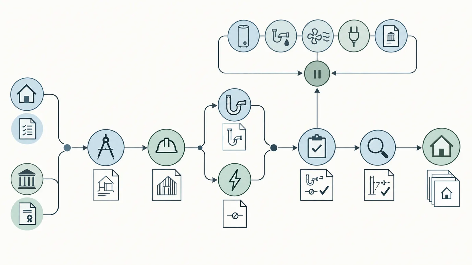
Complete the decision in a controlled sequence: homeowner brief, model freeze, room comparison, designer coordination, plumber drainage review, electrician load review, builder rough-in coordination, then pre-cover verification. Each handoff should produce a record that the next person can use without reinterpreting a room label.
The sequence is complete only when responsibility and evidence travel together. If the plumber has a drain sketch but the electrician has not received the final model rating plate, the handoff is incomplete; if the model changes after rough-in, the chain returns to the model-freeze step. The homeowner’s next decision is therefore the next unresolved record, not a preference for one room based on convenience.
Handoff 1: homeowner to designer and builder
Give the project team the household’s planned bedroom and bathroom count, peak hot-water uses, preferred location constraints, noise-sensitive rooms, storage expectations, service-access expectations, target equipment, utility or demand-response goals, and known panel or service limitations. State what is not yet known.
The homeowner owns the priorities, not the code interpretation. For example, “keep the heater out of the bedroom wall and preserve a clear service path” is a design priority. “A garage is permitted” is a jurisdictional conclusion that must come from the actual project team and AHJ.
The designer or builder should return a dimensioned plan showing candidate locations, room boundaries, doors, grilles, tank footprint, service zone, drain route, water route, electrical route, and access for future replacement. Require the exact manual to be named on the plan.
Handoff 2: designer to plumber
The plumber receives the room plan and identifies cold, hot, relief, condensate, pan and leak-protection routes. The plumber verifies elevations and access and flags any drain or sanitary-discharge issue for the actual jurisdiction. The plumber should state whether each route is gravity, pumped or unresolved and what happens if a pump or float fails.
Ask for a sketch with arrows and elevations, not only a parts list. The homeowner should be able to see where condensate ends, where pan water ends, and whether a relief discharge is independent. The plumber’s record should cite the exact model manual page for model-specific connections and mark local requirements as local requirements for the named jurisdiction.
Handoff 3: designer and builder to electrician
The electrician receives the exact model rating-plate data, manual revision, unit location, route length, panel and service information, planned whole-home loads, and any lower-amperage or 120-volt alternative. The electrician performs the applicable load and circuit design and returns the voltage, phase, circuit, protection, conductor and disconnect concept with the permit/inspection dependencies.
The homeowner should not ask for “a 30-amp outlet” as the complete scope. Ask for the designed circuit for the exact equipment, including the actual connection method, location, access, wet-location or other conditions if applicable, grounding and local review. The manual may specify one requirement while the adopted jurisdiction adds another; both need to be resolved by the responsible professional.
Handoff 4: builder to all trades before concealment
Before walls, ceilings or floors close, hold a coordination check with the final model and drawings in hand. Confirm:
- The tank can be delivered, placed upright and removed for future service.
- The floor, platform, blocking and drain pan or protection are complete as designed.
- The required free air, door/grille or duct arrangement is not blocked by framing, insulation or finishes.
- The service clearance remains available after drywall, trim, shelves and other equipment.
- The water pipes, valves and relief discharge match the plumbing plan.
- The condensate line has the model-specified size, elevation, slope or pump, plus the required failure response.
- The electrical route, panel, disconnect and equipment connection match the electrician’s design.
- The room’s final temperature assumptions and separation from vehicle exhaust, corrosive products and combustible storage remain valid.
Photograph concealed work with a tape measure or reference mark, save the final drawings, and record any approved change. A photo is evidence of what was visible at one time, not proof that a hidden system complies with every requirement.
Handoff 5: commissioning to ownership
At turnover, obtain the exact manual, model and serial number, warranty record, electrical panel label, shutoff locations, condensate destination, pan or leak-sensor behavior, filter access, maintenance instructions and the names of the plumber, electrician and builder. Have the installer document the final operating mode and any settings that affect the household’s expectations.
The supplied Rheem manual and A. O. Smith manual emphasize safe startup conditions, including filling the tank before energizing and keeping records for service. The homeowner’s ownership record should state who is allowed to reset, service, clean or replace each component. It should also explain what alarm, leak, overflow, freezing or loss-of-hot-water condition warrants immediate shutdown and professional service.
Resolve failure cases before rough-in becomes expensive #
When a comparison fails, preserve the failure evidence and choose the next decision explicitly: resolve the missing input, redesign the room, change the model, change the electrical service, or reject the candidate. A failed row is useful because it prevents an attractive but undocumented installation from becoming concealed rework.
The model manual or revision is missing
Observe: the proposal names only a brand, tank size or product family, or the linked manual does not match the rating plate.
Interpretation: room volume, clearance, condensate and electrical fields are not reliable. A product page or salesperson summary cannot stand in for the installation manual.
Safest next step: place the row on hold. Ask the builder or supplier for the exact model, current installation manual and rating-plate data. Recheck every field after receipt.
Next handoff: homeowner to builder/designer, then plumber and electrician.
The room volume passes but the airflow does not
Observe: the arithmetic exceeds the model’s minimum, but the door is sealed, an appliance occupies the room, the filter cannot be reached, or a duct route is blocked.
Interpretation: mathematical volume is not functional air exchange or service access. If the room is confined, the manual’s door, louver or duct conditions may control.
Safest next step: keep the wall or door design open. Have the designer/HVAC professional document net-free area, intake/exhaust arrangement, comfort impact and any fire or garage-separation issue.
Next handoff: designer/HVAC professional to builder, with manual page attached.
The garage has volume but falls below the temperature envelope
Observe: the space is unconditioned and the modeled low is below the selected model’s stated heat-pump range, or water and condensate lines can freeze.
Interpretation: the location may shift the unit to resistance operation or create freeze risk; the annual impact cannot be inferred from one threshold.
Safest next step: compare conditioned enclosure, freeze protection and another model using its own manual. Keep vehicle exhaust and storage out of any airflow path.
Next handoff: designer/HVAC professional and plumber; electrician if the model or load changes.
The condensate destination is nearby but too high
Observe: the drain is above the condensate outlet, the route cannot maintain the model’s slope, or the line would cross a concealed obstruction.
Interpretation: gravity drainage is not proven. A pump may be required, and the pump introduces power, float, overflow and maintenance obligations.
Safest next step: do not run a hidden line on the assumption that it will drain. Have the plumber document a gravity route or a model-compatible pump with failure shutoff and an approved destination.
Next handoff: plumber to designer and electrician.
The panel has an empty space but capacity is unknown
Observe: the proposal points to a blank breaker position without a whole-home load calculation, or the selected model voltage differs from the service.
Interpretation: spaces and service capacity are different questions. A model with 240 VAC requirements cannot be substituted onto a 208 VAC supply merely because the breaker fits.
Safest next step: stop electrical rough-in for this equipment. Give the electrician the exact model and complete load schedule; obtain the designed circuit and jurisdiction/utility path.
Next handoff: electrician to builder and designer; homeowner receives the dated record.
The shortest water route creates the worst occupied-space tradeoff
Observe: a closet beside bathrooms minimizes pipe distance but is beside a bedroom, below the model’s free-air requirement, lacks a drain or leaves no service space.
Interpretation: distribution efficiency is one criterion among air, sound, drainage, access and electrical coordination. A short pipe route cannot waive a model requirement.
Safest next step: score the basement, garage or another conditioned room with the same fields. Ask whether insulation, recirculation or distribution redesign can address distance without hiding a room failure.
Next handoff: homeowner priorities to designer, then plumber and builder.
The selected model changes after rough-in starts
Observe: the supplier substitutes a different product, voltage, tank size or generation.
Interpretation: the previous comparison is stale. Even a same-capacity replacement can alter filled weight, footprint, clearances, airflow, condensate and circuit.
Safest next step: freeze concealment in the affected area. Create a new worksheet row, attach the new manual and obtain written re-verification from the trades.
Next handoff: builder to homeowner, designer, plumber and electrician before approving the change.
The local rule is being quoted without a named jurisdiction
Observe: someone says “code requires” or “code allows” without naming a city, county, state, adopted edition or AHJ.
Interpretation: the claim may be a manufacturer instruction, model code, local amendment, utility rule or habit. The scope is unknown.
Safest next step: write the actual project city/state or county/state and ask the builder/designer to identify the AHJ and adopted provision. Until then, mark the local field unresolved.
Next handoff: builder/designer to the named AHJ or permit process; do not treat this guide as local legal advice.
The answer is still “not enough evidence”
That is a valid result. If the final row has an unresolved model, manual revision, jurisdiction, room temperature, drain elevation, floor support or load calculation, the best decision is to delay the related rough-in or select a documented alternative. The cost of carrying one open coordination item is usually easier to see before drywall than after a blocked filter, a pump that cannot drain, a circuit that fails review or a unit that is too close to an occupied room.
Use this minimum release rule:
| Release gate | Must be present before rough-in |
|---|---|
| Product | Exact model, rating plate or submittal, installation manual and revision |
| Room | Dimensioned free-air calculation, temperature range, airflow and service envelope |
| Water | Hot/cold route, relief route, condensate route, destination, pan/leak strategy |
| Electrical | Licensed electrician’s model-specific design and whole-home capacity record |
| Jurisdiction | Actual city/county/state, AHJ, adopted requirements and permit path identified |
| Handoffs | Named owner, dated verification and next action for every exception |
If any gate is a hold, the next decision is to resolve that gate—not to make the article or the worksheet say “pass.”
Make the final go/no-go decision and preserve the evidence #
Choose the candidate only when every material constraint is either passed by the responsible professional or explicitly redesigned and recorded; otherwise keep the row on hold. The final decision should name the exact model, room, jurisdiction, electrical configuration, condensate strategy, unresolved risks and next handoff.
A practical decision statement
Write one paragraph such as:
Illustrative format: For the proposed [exact model and manual revision] in [named room], the project team accepts the room-volume, temperature, airflow, service-access, water-route, condensate, protection and electrical design inputs shown in worksheet version [date]. The licensed electrician’s record [document] supports the proposed supply for the project at [city/state or county/state], and the qualified plumber’s record [document] supports the drain and protection concept subject to [named AHJ] review. Remaining hold: [specific item]. Owner: [name/role]. Next decision date: [date].
Do not copy the illustrative values into a real decision. The value of the paragraph is its structure: product, room, jurisdiction, evidence, owners and hold status appear together.
Keep a change log
Record what changed and why:
- Model or manual revision.
- Room dimensions, door, grille, duct or finished-wall change.
- Ambient assumption or conditioned/unconditioned status.
- Drain elevation, route, pump or destination.
- Pan, sensor, shutoff or leak-protection change.
- Service panel, load schedule, circuit, voltage or disconnect change.
- Water-pipe route, manifold or recirculation change.
- Local AHJ answer, permit comment or inspection condition.
For each change, note affected rows, responsible reviewer, document or photo, decision and date. A change log protects the homeowner from a common failure: each trade works from a different version of “the plan.”
Owner maintenance and review after installation
Location selection has maintenance consequences. Preserve air-filter access, condensate-pan and line access, drain visibility, electrical disconnect labeling, water shutoffs and the manual. Have the installer explain the normal operating sound, expected condensate destination and alarm response. Record the date for the manufacturer’s stated inspections and service, but do not invent a universal annual schedule when the exact manual differs.
The supplied A. O. Smith manual instructs visual checks of the lower drain pan, water piping, corrosive materials and combustible materials and says the filter and condensate work must be approached with power disconnected; it directs a qualified person when the homeowner lacks the necessary skills. The supplied Rheem manual similarly includes filter and condensate maintenance and warns that blocked lines can overflow. These are reasons to make access part of the original room decision, not reasons to ask a homeowner to open live equipment.
The decision in one sentence
The best HPWH rough-in location is the candidate room for which the exact model, free air, temperature, airflow, clearances, sound, floor support, water distribution, condensate, protection, electrical capacity and actual jurisdiction are all documented with named professional owners; if one of those inputs is missing, the correct result is a hold and a next handoff.
Heat Pump Water Heater Location-and-Rough-In Comparison Worksheet
Print or reuse this source-linked worksheet to compare candidate rooms and electrical configurations before rough-in.
Download the worksheet (PDF)Cite this guide
Brictale. “How to Compare Heat Pump Water Heater Locations and Electrical Options Before Rough-In.” Published 2026-10-06; updated 2026-10-06.
https://brictale.com/build/materials/compare-heat-pump-water-heater-location-electrical-options-before-rough-in · Read the Markdown version
Original contribution: Location-and-Rough-In Comparison Worksheet. A source-linked record for comparing candidate heat-pump water-heater rooms and electrical configurations before plumbing and electrical rough-in.
Sources and scope
Evidence behind this page
- The U.S. Department of Energy describes an HPWH decision-tool task covering panel capacity, water-heater location, water-heater size and condensate-drain installation specifics.
Field Validation of HPs and HPWHs
DOE project description; establishes decision dimensions and tool scope, not a site approval, code rule or product requirement.
Accessed · Link to this claim - ENERGY STAR says manufacturers typically require 450 or 700 cubic feet of free air space, with enough installation and service space, and directs readers to the model-specific installation guide.
Heat Pump Water Heater Design Considerations
ENERGY STAR Residential New Construction expert guide; typical program guidance, not a universal product or local-code requirement.
Accessed · Link to this claim - ENERGY STAR identifies sound, cooled exhaust air, climate, distance to hot-water uses and occupant comfort as location considerations, and discusses basements, garages and interior rooms as possible locations subject to the manual and local requirements.
Heat Pump Water Heater Design Considerations
ENERGY STAR design guidance; location examples are conditional and do not approve a specific home, climate or model.
Accessed · Link to this claim - ENERGY STAR describes passive and active airflow approaches for confined spaces and warns against ducting only intake or exhaust outdoors, ducting between a garage and the unit, placing exhaust near a thermostat, or using outdoor ducting in cold climates without the specified balanced arrangement.
Heat Pump Water Heater Design Considerations
ENERGY STAR guide airflow and ducting guidance; duct dimensions and climate suitability remain model- and design-specific.
Accessed · Link to this claim - ENERGY STAR says HPWH condensate must be drained away, generally by gravity to an appropriate drain such as a floor drain, sink or standpipe; it says not to discharge directly to DWV piping or the safety pan and notes that a condensate pump may be used when gravity drainage is impractical.
Heat Pump Water Heater Design Considerations
ENERGY STAR design guidance; exact outlet, trap, pump and sanitary-discharge arrangement must be checked against the model manual and actual jurisdiction.
Accessed · Link to this claim - ENERGY STAR says new-construction HPWH electrical requirements are similar to electric resistance tanks, describes 208/240-volt and 30-amp service as a common design point, notes that some 240-volt 15-amp products exist, and directs readers to the manual, NEC guidance and local codes.
Heat Pump Water Heater Design Considerations
ENERGY STAR new-construction guidance; it is not permission to substitute a circuit, breaker, conductor or voltage for a selected model.
Accessed · Link to this claim - ENERGY STAR says HPWHs meeting its Version 5.0 product specifications emit less than 55 dBA, and says some HPWHs have sound-pressure ratings of 45 dBA; it recommends considering room comfort and avoiding bedrooms and living areas.
Heat Pump Water Heater Design Considerations
ENERGY STAR Residential New Construction guide, Sound section; program/product rating context, not a site sound measurement or universal installation limit.
Accessed · Link to this claim - ENERGY STAR says 240-volt HPWHs using 15-amp breakers are available and are best suited to limited-service new construction or multifamily applications; it says their smaller resistance element gives them a lower first-hour rating than similarly sized 30-amp HPWHs.
Heat Pump Water Heater Design Considerations
ENERGY STAR Electrical Requirements section; category-level guidance, not approval of a selected model or circuit design.
Accessed · Link to this claim - The supplied Rheem AP23657 Rev 01 manual calls for a clean, dry location near hot-water demand, protection from freezing, a floor able to support the filled heater, service access, and model-specific clearances; it describes more than 700 ft³ as requiring no additional ventilation and gives confined-space alternatives.
Electric Residential Hybrid Water Heater Use & Care Manual, AP23657 Rev 01
Rheem manual supplied in the brief, © 2024; applies only to the covered Rheem product/manual revision and must be matched to purchased model.
Accessed · Link to this claim - The supplied Rheem manual specifies a 3/4-inch primary condensate connection, no reduction below the connection size, downward pitch of at least 1/8 inch per foot, a P-trap when connected to a sewer pipe, and a pump rated at least 2 gallons per day when no drain is available; it prohibits draining condensate into the heater pan.
Electric Residential Hybrid Water Heater Use & Care Manual, AP23657 Rev 01
Rheem manual supplied in the brief, pages 9-10; model-specific installation instruction, not a national plumbing rule.
Accessed · Link to this claim - The supplied Rheem manual requires a separate branch circuit with copper conductors, overcurrent protection and a suitable disconnecting means provided by a qualified electrician, with voltage and wattage taken from the rating plate and wiring conforming to applicable local codes or the NEC where specified.
Electric Residential Hybrid Water Heater Use & Care Manual, AP23657 Rev 01
Rheem manual supplied in the brief, pages 14-16; exact rating-plate values and local adoption/permit requirements control the project.
Accessed · Link to this claim - The supplied Rheem AP23657 Rev 01 manual defines its room-size requirement as unoccupied free-air space, excluding furniture, appliances and other objects occupying the room volume; it describes more than 700 ft³ without additional ventilation and smaller arrangements with specified airflow provisions.
Electric Residential Hybrid Water Heater Use & Care Manual, AP23657 Rev 01
Rheem manual supplied in the brief, pages 6-8; model/manual-specific room and airflow guidance, not a universal room rule.
Accessed · Link to this claim - Rheem product literature for the covered ProTerra product family reports quiet operation at 45 dBA, measured at 6.28 feet using third-party certified testing procedures.
Rheem ProTerra Hybrid Electric Specifications, RH-HPE-200 Rev. 7
Rheem product literature dated 7/24; rating and test condition apply to the covered product literature, not every Rheem model or a finished-room measurement.
Accessed · Link to this claim - The supplied A. O. Smith FHPT-50 manual calls for a centrally located indoor unit with unrestricted airflow and 700 ft³ minimum installation space, states a 6-inch minimum at the outlet-side wall, separately shows 6 inches above the unit for filter maintenance, and recommends 3 feet from obstructions at the back, left and right for future service.
A. O. Smith FHPT-50 Instruction Manual, 326880-003
A. O. Smith FHPT-50 manual supplied in the brief, pages 4-5 and 10-11; applies to that model/manual, not all HPWHs or a local code determination. The manual does not state a 6-inch minimum at the sides and top.
Accessed · Link to this claim - The supplied A. O. Smith FHPT-50 manual lists a filled weight of 573 pounds for its 50-gallon model and requires flooring or a platform capable of supporting the heater and water; it also calls for provisions to protect the area from water damage.
A. O. Smith FHPT-50 Instruction Manual, 326880-003
A. O. Smith FHPT-50 manual supplied in the brief, installation and location sections; model-specific filled-weight and installation guidance, not a structural design.
Accessed · Link to this claim - The supplied A. O. Smith FHPT-50 manual directs the installer to select a location near the center of the water-piping system and to keep the drain and controls easily accessible for operation and service.
A. O. Smith FHPT-50 Instruction Manual, 326880-003
A. O. Smith FHPT-50 manual supplied in the brief, location requirements; model-specific planning direction, not a formula for room selection.
Accessed · Link to this claim - The supplied Rheem AP23657 Rev 01 manual directs the installer to locate the heater as near as practical to the area of greatest heated-water demand, states that long uninsulated hot-water lines can waste energy and water, and requires access panels to remain removable for inspection and service.
Electric Residential Hybrid Water Heater Use & Care Manual, AP23657 Rev 01
Rheem manual supplied in the brief, location section; model-specific installation guidance, not a distribution-loss calculation.
Accessed · Link to this claim - The supplied A. O. Smith FHPT-50 manual requires power to be turned off before specified filter and service tasks and directs the operator to contact a qualified person when needed; its location and checklist sections require accessible drain, controls and service space.
A. O. Smith FHPT-50 Instruction Manual, 326880-003
A. O. Smith FHPT-50 manual supplied in the brief, installation, maintenance and troubleshooting sections; safety and service guidance for that model.
Accessed · Link to this claim - The supplied Rheem AP23657 Rev 01 manual includes air-filter and condensate maintenance and warns that water from the condensate-pan overflow slot indicates both condensate drain lines may be blocked and requires immediate action.
Electric Residential Hybrid Water Heater Use & Care Manual, AP23657 Rev 01
Rheem manual supplied in the brief, installation checklist and care sections; model-specific maintenance warning, not a universal service schedule.
Accessed · Link to this claim - The supplied A. O. Smith FHPT-50 manual requires indoor, vertical, level installation on a floor capable of supporting the filled heater, unrestricted airflow, 700 cubic feet, a 6-inch minimum at the outlet-side wall, 6 inches above the unit for filter maintenance, service access, freeze protection, and a location not subject to specified corrosive contaminants; it recommends 3 feet from obstructions at the back, left and right for future service, and its checklist records 573 pounds for a filled 50-gallon unit.
A. O. Smith FHPT-50 Instruction Manual, 326880-003
A. O. Smith FHPT-50 manual supplied in the brief, pages 4-5 and 10-11; applies to that model/manual and not to all A. O. Smith or HPWH products. The manual does not state a 6-inch minimum at the sides and top.
Accessed · Link to this claim - The supplied A. O. Smith FHPT-50 manual describes a 3/4-inch primary and 1/2-inch overflow condensate arrangement, termination no more than 6 inches above an adequate drain, a condensate pump when the drain is unavailable or too high, conditioned-area routing, freeze protection, separate lines and pump-failure shutoff protection.
A. O. Smith FHPT-50 Instruction Manual, 326880-003
A. O. Smith FHPT-50 manual supplied in the brief, pages 6-7; model-specific instruction and subject to local code.
Accessed · Link to this claim - The supplied A. O. Smith FHPT-50 manual requires a 240 VAC single-phase 30-amp power supply, says not to use 208 VAC, and directs electrical work to a qualified electrician and applicable codes or the current NEC where no local or state code applies.
A. O. Smith FHPT-50 Instruction Manual, 326880-003
A. O. Smith FHPT-50 manual supplied in the brief, pages 9-10; not a general rule for other models or a substitute for the electrician’s design.
Accessed · Link to this claim - The National Laboratory of the Rockies report describes laboratory evaluation of five integrated residential HPWHs across operating conditions representative of U.S. climate regions and reports that controls and design features affected performance among the tested units.
Laboratory Performance Evaluation of Residential Integrated Heat Pump Water Heaters
Technical-report abstract; laboratory results for five tested units and operating conditions, not a guarantee for an untested model or particular room.
Accessed · Link to this claim - AHRI says its Product Performance Certification Program tests and certifies HVACR and water-heating equipment against published claims through independent third-party laboratory testing, and identifies its public directory as a place to search certified product performance.
AHRI Certification Programs and AHRI Directory
AHRI program description; certification status and ratings must be checked for the exact product and rating, and certification does not approve a room, circuit or local installation.
Accessed · Link to this claim - AHRI describes its public Directory of Certified Product Performance as a place where engineers, contractors, regulators and consumers can search by product lines, certified ratings or brands for certified performance information.
AHRI Directory of Certified Product Performance
AHRI directory page; use it to check the exact product and certified rating where applicable. A directory result does not approve a room, circuit, local code or installation.
Accessed · Link to this claim - In the ENERGY STAR guide's described passive ventilation arrangement, the minimum total net-free area is 240 square inches or more with high and low openings; for certain active ducting arrangements, the guide describes 130 square inches of net-free area. These figures apply only to the configurations described in that guide and do not replace the selected model manual or a project-specific design.
Heat Pump Water Heater Design Considerations
ENERGY STAR Residential New Construction guide, ventilation examples; configuration-specific guidance, not a universal HPWH opening requirement or local approval.
Accessed · Link to this claim - The supplied Rheem AP23657 Rev 01 manual's clearance diagram lists 0 inches at the rear, 0 inches at the sides and 6 inches at the top for the covered product/manual revision; service, drain and access requirements still govern the coordinated installation.
Electric Residential Hybrid Water Heater Use & Care Manual, AP23657 Rev 01
Rheem manual supplied in the brief, clearance diagram on page 4; exact model/manual-specific dimensions, not a universal clearance rule or local approval.
Accessed · Link to this claim - The supplied Rheem AP23657 Rev 01 manual describes confined-space arrangements for rooms below 700 ft³ down toward 450 ft³, with reduced efficiency and performance output; it states that the reduced-performance condition was not evaluated and is not recommended for optimal performance.
Electric Residential Hybrid Water Heater Use & Care Manual, AP23657 Rev 01
Rheem manual supplied in the brief, room-size and confined-space guidance on pages 6-8; applies only to the covered product/manual revision and does not make a smaller room automatically acceptable.
Accessed · Link to this claim - For the supplied A. O. Smith FHPT-50 manual, heat-pump operation in Efficiency Mode requires ambient air above 45°F and below 120°F; outside that range, the electrical elements activate to meet demand.
A. O. Smith FHPT-50 Instruction Manual, 326880-003
A. O. Smith FHPT-50 manual supplied in the brief, ambient and operating-mode guidance; model/manual-specific threshold, not a universal HPWH operating envelope.
Accessed · Link to this claim - The supplied Rheem AP23657 Rev 01 manual recommends installing the covered hybrid water heater where ambient temperatures do not exceed 145°F and separately warns that insufficient air exchange increases energy consumption.
Electric Residential Hybrid Water Heater Use & Care Manual, AP23657 Rev 01
Rheem manual supplied in the brief, location guidance on page 4; model/manual-specific recommendation, not a universal HPWH limit.
Accessed · Link to this claim - The supplied A. O. Smith FHPT-50 manual warns not to plug or remove the temperature-and-pressure relief valve or its discharge path and says a dripping or leaking relief valve must be handled by a qualified person; it identifies the discharge pipe as a separate safety path.
A. O. Smith FHPT-50 Instruction Manual, 326880-003
A. O. Smith FHPT-50 manual supplied in the brief, temperature-and-pressure relief and condensate guidance; model/manual-specific safety instruction, not remote diagnosis or local plumbing approval.
Accessed · Link to this claim - The supplied Rheem AP23657 Rev 01 manual requires the water heater to be completely full of water before electrical power is turned on or the unit is operated, and its startup checklist also calls for purging air from the water heater and piping.
Electric Residential Hybrid Water Heater Use & Care Manual, AP23657 Rev 01
Rheem manual supplied in the brief, safety and installation checklist sections on pages 3, 13-14 and 19; model/manual-specific startup requirement.
Accessed · Link to this claim - The supplied A. O. Smith FHPT-50 manual says not to turn on power unless the tank is completely filled with water and instructs the installer to open a hot-water faucet until air is purged and water flows uninterrupted before applying electrical power.
A. O. Smith FHPT-50 Instruction Manual, 326880-003
A. O. Smith FHPT-50 manual supplied in the brief, startup and maintenance guidance; model/manual-specific startup requirement.
Accessed · Link to this claim