How to Compare Conventional, Advanced, and Double-Stud Wall Framing Before Design Freeze
Compare conventional, advanced, and double-stud wall framing before design freeze—load paths, thermal bridges, openings, services, cladding and verification.
The short answer
Choose a wall layout only after your design professional confirms the load path and your enclosure team maps climate-specific air, vapor, water, and insulation layers. Advanced framing can reduce framing interruptions when geometry and crew practice support it; double-stud framing can add insulation depth and service space but increases wall-depth and moisture coordination. Freeze the option only when openings, cladding, services, inspections, and future backing are documented.How to Compare Conventional, Advanced, and Double-Stud Wall Framing Before Design Freeze
Choose a wall layout only after your design professional confirms the load path and your enclosure team maps climate-specific air, vapor, water, and insulation layers. Advanced framing can reduce framing interruptions when geometry and crew practice support it; double-stud framing can add insulation depth and service space but increases wall-depth and moisture coordination. Freeze the option only when openings, cladding, services, inspections, and future backing are documented.
This guide is for a United States homeowner at schematic design or design development. It compares three wood-framed approaches as assemblies, not as isolated stud sizes. “Conventional” means a regular single-stud baseline selected by the project designer, often 2x4 or 2x6 studs at 16 inches on center. “Advanced” means a coordinated family of framing reductions and alignments, not simply 2x6 studs at 24 inches on center. “Double-stud” means two framed lines separated or placed next to each other to create a deeper insulated and/or service cavity. The actual choice belongs in the construction documents for the named project.
The governing boundary is jurisdictional. Identify the city or county building department, the state code agency where applicable, the code edition and local amendments adopted for this address, and the project's wind, seismic, snow, flood, wildfire, and exposure conditions. The 2021 International Residential Code is a model-code reference; its wall chapter connects framing, sheathing, bracing, openings, and design conditions, but the online model text does not prove what your local authority having jurisdiction (AHJ) has adopted. Read the 2021 IRC wall-construction reference at ICC and ask the local building official or permit professional for the adopted text and amendments.
1. Start with the decision boundary, not the insulation number #
The right first choice is the layout that your project can structurally justify, thermally detail, price, build, inspect, and maintain as one coordinated wall. Conventional framing is usually the simplest baseline; advanced framing is a good candidate when the plan is regular and the team can execute reduced framing and aligned loads; double-stud framing is a good candidate when the project values deeper insulation and a service zone enough to justify extra wall depth, opening details, and moisture coordination.
What you are actually choosing
Treat a wall as a chain of dependent decisions:
- What loads arrive at the wall from the roof, upper floors, snow, wind, seismic actions, and attached elements?
- Where do the structural sheathing, braced wall segments, headers, posts, hold-downs, plates, and foundation connections transfer those loads?
- Where do the insulation, air-control, vapor-control, and water-control layers run without interruption?
- At what plane are windows, doors, cladding, trim, flashing, decks, porches, and utilities attached?
- Which trade owns each detail, and what observable record proves that it was installed before it disappears?
- What will a future owner need to fasten, open, reroute, inspect, or repair?
APA's wall-construction guide calls exterior walls a critical structural component and covers sheathing, bracing, shear walls, wind uplift, advanced framing, and force transfer around openings. That scope is a useful reminder that a framing comparison is not just an insulation comparison. The guide is an overview for designers and builders, not a stamped design for your address. See the APA wall-construction guide.
The three layouts can be described this way:
| Layout | Basic arrangement | Main opportunity | Main coordination burden | Good first question |
|---|---|---|---|---|
| Conventional single-stud | One regular structural stud line, commonly 2x4 or 2x6, with sheathing, weather-resistive barrier, cladding, and interior finish coordinated around it | Familiar pricing, detailing, and trade workflow | More framing interruptions through corners, intersections, plates, headers, and openings can reduce the insulated portion of the wall | Can the baseline meet the project's load, enclosure, comfort, and space goals with details the local team already knows? |
| Advanced single-stud | One structural stud line with a deliberate grid, reduced unnecessary studs, aligned framing, insulated corners and headers where permitted, and coordinated openings | Less lumber in selected locations and less thermal bridging than an over-framed baseline | Structural exceptions, irregular geometry, utilities, cabinet backing, drywall backing, and crew discipline must be resolved early | Is the plan regular enough for the savings and will the engineer and framer document every exception? |
| Double-stud | Two stud lines separated or adjacent, usually with one line carrying the primary structural and sheathing functions and the other creating depth, insulation, or a service zone | Deeper insulation, less direct framing bridge through the clear wall field, and a potentially useful interior routing zone | Wall thickness, openings, window installation, floor lines, vapor and air control, cladding support, and inspection access become more complex | Does the added depth and coordination buy a project goal that the other two options cannot meet more simply? |
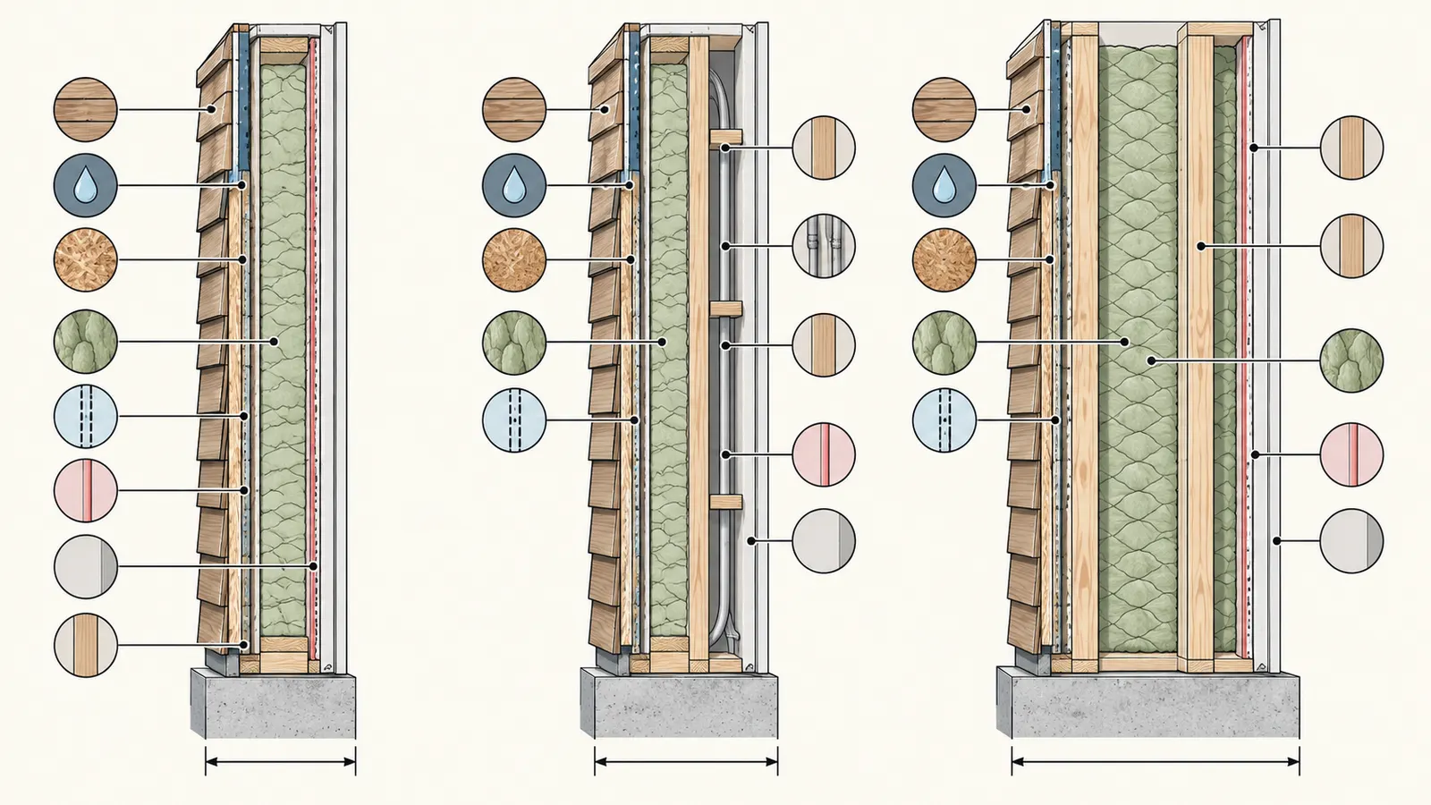
Advanced framing is a package, not a slogan. DOE Building America describes two-foot modular planning, studs up to 24 inches on center, two-stud corners, aligned framing, and selected single headers or top plates as examples, while warning that some techniques may not be allowed under certain high-wind, seismic, or local conditions. Review the DOE Advanced Wall Framing guide. A plan that says “advanced framing” without a wall-framing schedule, opening schedule, corner/intersection details, and structural notes is not ready for a meaningful comparison.
The prerequisite packet
Before you ask for a price or a final recommendation, assemble one packet. The homeowner can collect most of the inputs; qualified design professionals must interpret the structural and code questions.
| Input to collect | Where it comes from | Why the framing choice depends on it | Person who confirms it |
|---|---|---|---|
| Project address and AHJ | Deed, survey, permit portal, local building department | Names the actual jurisdiction and exposes local amendments, review path, and adopted code | Homeowner with permit professional or designer |
| Climate zone and moisture context | DOE/PNNL climate lookup, address, elevation, site observations | Influences insulation, condensation-control, vapor-control, drying, and cladding decisions | Building-science designer or architect |
| Wind, seismic, snow, flood, and wildfire conditions | AHJ records, site data, adopted code, geotechnical and structural inputs | Can change bracing, connections, stud size, opening limits, sheathing, foundation, and cladding requirements | Structural engineer or qualified design professional |
| Floor, roof, and upper-floor geometry | Schematic plans, truss or rafter concept, sections | Determines whether loads stack over studs and where transfer beams, posts, or offset conditions occur | Architect and structural engineer |
| Window and door sizes and locations | Room plan, elevations, daylight and egress brief | Determines header, jamb, sill, cripple, flashing, and interior/exterior return dimensions | Architect, structural engineer, window professional |
| Cladding and support system | Exterior elevations and product manuals | Determines sheathing, furring, drainage cavity, fastener penetration, and flashing plane | Architect and cladding designer or installer |
| Service routing and backing | Mechanical, plumbing, electrical, cabinetry, and built-in plans | Determines whether a cavity is penetrated, reserved, or used as a service zone | Mechanical, plumbing, electrical, and interior teams |
| Future changes | Homeowner's room-by-room plan | Determines backing, chase space, access panels, and areas where future penetrations are unacceptable | Homeowner with architect and trades |
The next decision after this packet is not “which wall has the highest R-value?” It is “which two complete wall sections should the team develop to permit-level detail?” Request one conventional baseline, one advanced option, and one double-stud option only if the double-stud case solves a stated project requirement. Comparing incomplete sketches creates false certainty.
Compact originality brief
Current answers commonly explain advanced framing, double-stud walls, or high-performance assemblies separately, while generic comparisons stop at 2x4 versus 2x6. The missing decision is the homeowner's design-freeze choice: who confirms the load path, where control layers move, how openings and services change, and what evidence is required before work is covered. This article's original contribution is the “Framing-layout choice matrix and room-by-room freeze worksheet.” It can be checked by substituting a real plan's dimensions, asking the named professionals to mark the load path and control layers, and comparing the resulting inspection records with the matrix. It is a decision aid, not engineering, code approval, a hygrothermal simulation, a bid, or a measured study.
2. Confirm the load path and openings before optimizing the wall #
A framing layout is acceptable only after the structural designer has shown how roof, floor, lateral, and attachment loads pass through the wall to the foundation under the project's actual wind, seismic, snow, and geometry conditions. Do not select advanced or double-stud framing first and ask a professional to make the loads fit afterward.
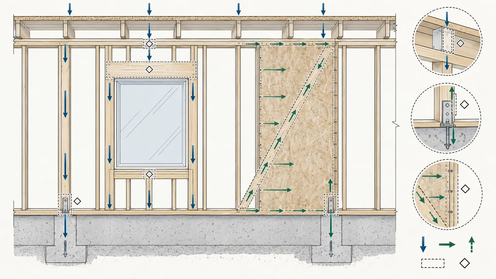
Draw the load path in plain language
Ask for a marked-up section and plan that answers these questions:
- Where does each roof rafter, truss, floor joist, beam, and upper-story wall bear?
- Are the roof and floor members aligned over the studs, or is there an offset that requires a beam, post, ledger, blocking, or transfer detail?
- Which wall segments resist gravity loads, wind pressure, uplift, and in-plane shear?
- Which sheathing panels, fastener schedules, hold-downs, straps, anchors, and foundations complete the path?
- What happens at corners, intersecting walls, garage openings, large window walls, porch roofs, and stair openings?
- Which parts are prescriptive for this project and which parts are engineered?
The ICC model-code wall text illustrates why the answer cannot be reduced to a stud label: its provisions tie wall sheathing and framing to wind pressure tables, spacing, height, openings, bracing, species, and other conditions. Those tables are not a permission slip for your project; they show the categories your engineer and AHJ must evaluate. Use the ICC Chapter 6 reference as a question list.
The APA guide likewise treats wall sheathing, bracing, shear, wind uplift, and force transfer around openings as coordinated wall-system topics. APA's wall guide lists these subject areas. Your design record should name the structural designer responsible for the project and the exact jurisdiction whose permit review governs it.
How each layout changes structural questions
Conventional framing gives the structural designer a familiar baseline, but familiar does not mean automatically adequate. A conventional wall can still need engineered headers, posts, portal frames, shear walls, hold-downs, special connections, or nonstandard framing around large openings. Its advantage is that the structural logic is often easy for the builder and inspector to recognize when the plans are clear.
Advanced framing removes or relocates material in places that are often doing more than one job. A two-stud corner may need a drywall backing strategy and a continuous insulation strategy. A reduced jamb may still need the required bearing and fastening. A single top plate depends on the specified splice, ties, intersections, and load alignment. A 24-inch layout can change sheathing edge support, cladding attachment, cabinet backing, and the position of every opening. DOE's guide explicitly warns that high-wind, seismic, and local circumstances can limit techniques, so treat the structural review as a prerequisite rather than an afterthought. Read the DOE warning on local acceptance.
Double-stud framing separates the visual idea of a deep insulated wall from the structural question of which line actually carries loads. The outer line may be the structural wall, the inner line may be a service or finish wall, or the design may use a different arrangement. The gap, ties, sheathing, floor connections, and top and bottom transitions all need a drawing. Two frames do not automatically mean two independent load paths, and an interior stud line does not become a structural beam merely because it is continuous.
Openings are the stress test
Windows and doors expose weak comparisons because an opening interrupts the clear wall field. Record each opening's width, height, sill elevation, head elevation, adjacent corner distance, wall orientation, story, roof or floor load above, and required egress or access function. Then ask the structural designer to show the header, king and jack studs, cripple studs, sill, sheathing transfer, fasteners, and any posts or straps.
Advanced framing seeks to limit opening framing to what structural and spacing requirements need. DOE Building Science Education explains that unnecessary king, jack, and cripple studs consume insulated cavity space and create thermal bridges; it does not authorize a homeowner to remove members from a plan. Use the DOE opening-framing guidance, then compare the actual opening schedule with the structural drawings.
Double-stud walls need two opening decisions: the structural opening and the finished opening. The window may sit toward the exterior, near the middle, or toward the interior of a thick wall. That choice affects sill pan and head flashing, drainage, jamb returns, interior trim, shades, insect screens, exterior casing, cladding transitions, and the ability to replace the unit later. If the inner frame is offset from the outer frame, show how the opening is framed and supported rather than drawing a single rectangle through both walls.
Structural verification record
Before design freeze, obtain these records in the project folder:
- A plan showing bearing and braced wall lines, shear segments, and major openings.
- Sections showing roof, floor, wall, foundation, and attachment load transfer.
- A wall-framing schedule naming stud size, spacing, grade or species assumptions, plates, corners, intersections, headers, posts, and blocking.
- A sheathing and fastening schedule, including any engineered panels, straps, hold-downs, or proprietary connectors.
- Structural notes that identify design loads, assumptions, and the responsible professional.
- The AHJ's plan-review comments or a written response path for alternate or engineered methods.
The homeowner can check that these records exist and that the same wall label is used on plans, elevations, sections, and the builder's scope. The homeowner should not size a header, remove a stud, substitute a fastener, or approve a bracing change. Structural work, temporary bracing, work at height, and concealed-load-path decisions belong to qualified professionals following the approved documents.
The handoff is complete when the architect or designer gives the structural set to the estimator and framer, the engineer reviews the proposed layout, and the builder returns any constructability exceptions before pricing is treated as final. The next decision is whether the selected structure can carry the enclosure and service strategy without late field improvisation.
3. Compare effective thermal performance and every control layer #
Compare complete wall assemblies using effective or whole-wall reasoning, not the nominal R-value printed beside a cavity. The framing fraction, corners, plates, headers, intersections, floor lines, openings, fasteners, air leakage, moisture, and exterior insulation can change the result; double-stud depth is valuable only when the control layers and installation quality support it.
Nominal insulation is only one input
Nominal cavity R-value describes insulation material under a stated thickness and product condition. It does not describe the average heat flow through a wall containing wood studs, plates, headers, corners, window edges, floor bands, and penetrations. Wood framing occupies area that could otherwise contain insulation and acts as a thermal bridge. DOE Building America reports that reducing unnecessary framing can increase insulated area and reduce thermal bridging, but its historical savings results are not a fixed promise for a new home. See the DOE advanced-framing evidence and its study limits.
Conventional framing usually has the most predictable clear-wall depth but can have a larger framing fraction when corners, intersections, headers, and openings are built with multiple members. Advanced framing tries to lower that fraction while preserving required strength and backing. Double-stud framing places framing lines apart so the clear field can contain more insulation and the direct bridge through the field can be reduced, but the floor line, openings, corners, and fasteners still need attention.
The Building America Solution Center describes double-stud construction as two stud-framed walls forming a deep cavity and requires the air-control and vapor-control layers to be selected for the wall type and climate zone. It also requires insulation to be installed without gaps, compression, or voids. Read PNNL's double-wall installation guidance. The important comparison is therefore “what effective assembly can this project install and verify?” rather than “which option has the largest nominal number?”
The durable-home report from Building Science is a useful bounded example of the same systems principle: structural requirements, water and vapor management, material durability, and energy efficiency were considered together in a post-Katrina New Orleans design. It is not a universal coastal specification, but it supports keeping those decisions in one review rather than optimizing insulation in isolation. Read the durable-home report and its regional scope.
Name the control-layer planes
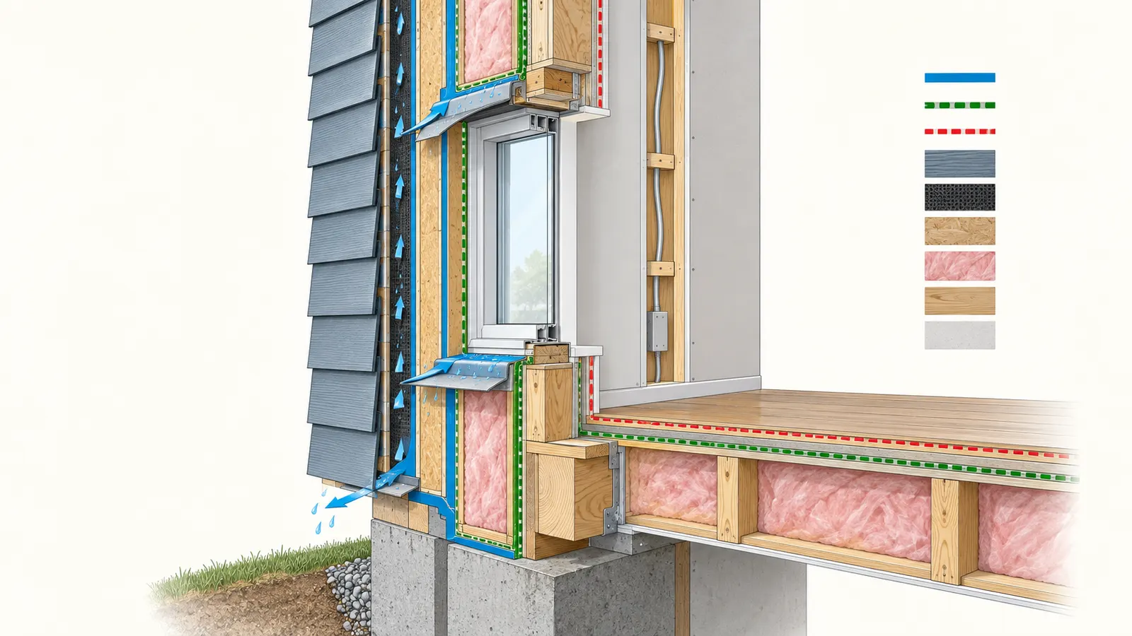
For each candidate wall, draw a continuous red line for air control, a blue line for water control, a dashed line for vapor control, and a shaded band for insulation. Label the plane at every transition:
- foundation-to-sill and slab or floor edge;
- bottom plate and exterior sheathing;
- corners and interior-to-exterior wall intersections;
- roof-to-wall and floor-to-wall transitions;
- window and door heads, jambs, and sills;
- porch roofs, decks, balconies, and penetrations;
- electrical, plumbing, mechanical, and ventilation penetrations;
- cladding joints, base, top, inside corners, and outside corners.
The control lines do not have to be in the same physical plane, but their continuity and interfaces must be intentional. A double-stud wall can put a service cavity inside the air barrier, outside it, or between layers depending on the design. An advanced wall can pair cavity insulation with exterior continuous insulation or a service cavity. A conventional wall can be simple to detail, but simplicity disappears if every trade cuts the same air or water layer.
Climate zone is a starting input, not a national design answer. DOE's climate-specific guidance links to a PNNL tool that looks up climate by county or ZIP and presents assemblies intended to meet the 2021 IECC and IRC thermal-efficiency and condensation-control requirements. Confirm the actual jurisdiction, adopted code edition, amendments, compliance path, and permit interpretation for the address. Use DOE's climate-specific guidance for the research starting point.
PNNL's double-wall code-compliance brief states that double-stud framing is not specifically addressed as a complete system in the IRC or IECC, while insulation, moisture, and air-leakage requirements still need review. It also notes that its climate and code examples are tied to particular editions. That is why a thick-wall sketch needs a documented air-barrier and vapor-control strategy and, where appropriate, project-specific hygrothermal analysis. Review the PNNL double-wall code boundary.
Water management stays outside the stud comparison
Do not treat a deeper cavity as a substitute for water management. Building Science's research describes a functional drained wall as a coordinated rainscreen or cladding screen, drainage plane or capillary break, drainage gap or cavity, flashing that directs water out, and weep or drain holes. See the five-component drainage description.
That means every candidate wall section must show where water that reaches the back of the cladding goes next. A wall with a perfect-looking insulation field can still fail if the window sill drains into the assembly, the flashing is not lapped, the cladding fasteners bridge a drainage path, or the bottom outlet is blocked. The Building Science report also explains that drainage does not remove all retained moisture and that ventilation or other drying mechanisms can matter. Its laboratory methods do not prescribe one gap size for every cladding, wind exposure, or jurisdiction. Read the report's limits on storage and drying.
The practical test is a section walk. Start at the exterior face and point inward: cladding, attachment or furring, drainage space, water-resistive barrier or drainage plane, sheathing, structural frame, insulation, air-control layer, vapor-control layer where required, service space, drywall, and finish. At a window, point from the sill to the exterior outlet and then from the interior finish to the air-control seal. If two people cannot point to the same sequence, the wall is not ready to be frozen.
Moisture limits for thick walls
A double-stud wall can create more insulation depth while also creating more material and interface depth in which moisture can be stored or moved. A DOE case study monitored a double-stud cellulose wall in Massachusetts Climate Zone 5A with temperature, relative-humidity, and moisture-content sensors and framed the need to understand thick-wall moisture behavior. That monitored assembly cannot be generalized to every climate, insulation, sheathing, interior humidity level, or cladding. Read the DOE case-study scope.
For a cold or mixed climate, ask whether interior moisture can reach a cold condensing surface, whether air leakage can carry more moisture than vapor diffusion, whether the assembly can dry toward one or both sides, and what happens during a power outage or a period of high indoor humidity. For a hot-humid or marine climate, ask whether exterior heat and humidity drive moisture inward and whether the specified control layers remain compatible with the cladding and interior finish. For a dry climate, still account for rain, irrigation, snow melt, and construction wetting.
The safe next step is not to choose a generic vapor retarder from an internet diagram. Give the designer the climate zone, indoor humidity assumptions, HVAC strategy, cladding, sheathing, insulation, exterior insulation, and construction sequence. Ask for a wall-specific control-layer detail and a statement of the code-compliance path. The next handoff is from the selected assembly to window, cladding, and service details.
4. Coordinate wall depth, openings, cladding, and services #
Choose the framing option only after a finished wall section proves how windows, doors, cladding, trim, services, cabinets, and future changes fit within the actual wall depth. A rough opening is not a complete opening detail; the important measurements run from finished interior surfaces through the air, water, insulation, and structural layers to the exterior cladding plane.
Window and door geometry
For every window and exterior door, make a room-side and exterior-side elevation plus a section. Record:
- rough-opening width and height;
- finished opening width and height;
- sill height, head height, and adjacent trim;
- unit frame depth and extension requirements;
- the planned installation plane;
- sill pan, jamb, head flashing, and end-dam approach;
- drainage path below the sill;
- interior jamb return and casing depth;
- exterior trim, cladding, and sealant interfaces;
- replacement path and access for future maintenance.
Conventional walls often make the rough-opening-to-finish sequence familiar, but the actual unit, flashing system, cladding, and wall layers still control the detail. Advanced framing can reduce unnecessary members around the opening, but it also makes the structural minimum and the sheathing transfer more explicit. Double-stud walls add the question of how the deep opening is returned and where the window sits in that depth. A deep jamb may improve shade or trim options in one room and make a later replacement more disruptive in another.
The DOE opening-framing guidance says to limit king, jack, and cripple studs to what the structural and spacing requirements need. Treat that as a coordination prompt: the architect, structural designer, and framer should agree on the opening schedule, and the window installer should confirm that the specified unit can be flashed and supported at the selected plane. Use the DOE opening guidance at the design review.
Cladding, attachment, and drainage
Cladding is not a cosmetic afterthought. Brick veneer, fiber cement, wood siding, stucco, metal panels, stone veneer, and rainscreen systems place different demands on sheathing, support, fasteners, furring, drainage, flashing, fire separation, and movement joints. The wall comparison should identify the cladding family before the wall depth is frozen.
For each elevation, ask the designer or cladding professional to show the attachment plane and the effective fastener penetration. A double-stud wall may need long fasteners or a dedicated furring grid; a service cavity may make it harder to find the structural line; advanced framing may leave fewer studs under a cladding joint than a conventional layout. A cladding installer should not discover the wall's structural spacing when the first courses are being set.
Use the drainage sequence from the wall section as the verification list: screen, drainage plane, cavity, flashing, and outlet. At windows, doors, decks, roof-wall intersections, and base conditions, mark the intended lap direction and the location where water exits. Building Science describes drainage and drying as mechanisms that still retain some moisture; therefore, “there is a weather-resistive barrier” is not enough evidence that the complete wall drains. Review the drainage and drying research.
Services and the service-zone choice
The service question is often the most persuasive argument for a double-stud wall, but only when the zone is deliberately reserved. Decide whether electrical cables, boxes, low-voltage wiring, plumbing branches, ventilation ducts, and small mechanical lines will sit inside the primary air barrier, outside it, or in a separate service cavity. Then show the penetrations that remain.
Conventional walls are familiar to many trades, but a stud cavity is not an unlimited chase. Every box, pipe, or duct can interrupt insulation and air sealing, and large services can force fur-outs or soffits. Advanced framing can create more insulated field area but may provide less predictable backing at corners and intersections. The two-foot grid and reduced corners need a drywall, cabinet, and utility plan.
Double-stud walls can reserve an interior frame for wiring and plumbing, reducing some penetrations of the outer air-control or insulation layers. That benefit is lost if the service wall is filled with unplanned ducts, if the framing lines are not labeled, or if trades cut through the wrong control layer. A service cavity also consumes floor area and may change built-in cabinet depth, baseboard, stair width, corridor clearance, and room dimensions.
Create a “no-penetration” map. Color the primary air barrier red and mark every electrical, plumbing, mechanical, and fastening point that crosses it. For each crossing, name the installer, sealing method, inspection moment, and photographic record. For the service zone, mark future access panels, shutoffs, cleanouts, junction boxes, and likely replacement routes. The responsible mechanical, plumbing, and electrical professionals must coordinate these locations; the homeowner can demand that the plan names the handoff and record.
Cabinets, fixtures, and future changes
Do not count only the framing lumber when comparing future flexibility. A homeowner may later install wall cabinets, grab bars, shelving, heat-pump heads, televisions, exterior awnings, railings, or storage systems. The selected layout should show continuous backing, blocking, or a permitted attachment strategy at those locations.
Advanced framing may reduce the number of convenient studs behind a finish. That is a manageable choice when the cabinet and blocking plans are issued before framing. Double-stud walls can provide a service or finish frame but do not let every screw find structural support; the two frames may have different capacities and positions. Conventional framing may offer a familiar fastening rhythm but still requires backing at the exact load locations.
Add a room-by-room backing sheet to the design package. For each wall, list cabinets, plumbing fixtures, toilets, grab bars, handrails, shelves, artwork, TVs, exterior penetrations, and likely future equipment. For each item, state the fastener plane, backing type, maximum assumed load if the professional provides one, and “do not drill” zones. The next handoff is to the framer and the interior or cabinetry team, with the structural designer consulted where the attachment is heavy, elevated, or exposed to wind.
5. Use the framing-layout choice matrix and worksheet #
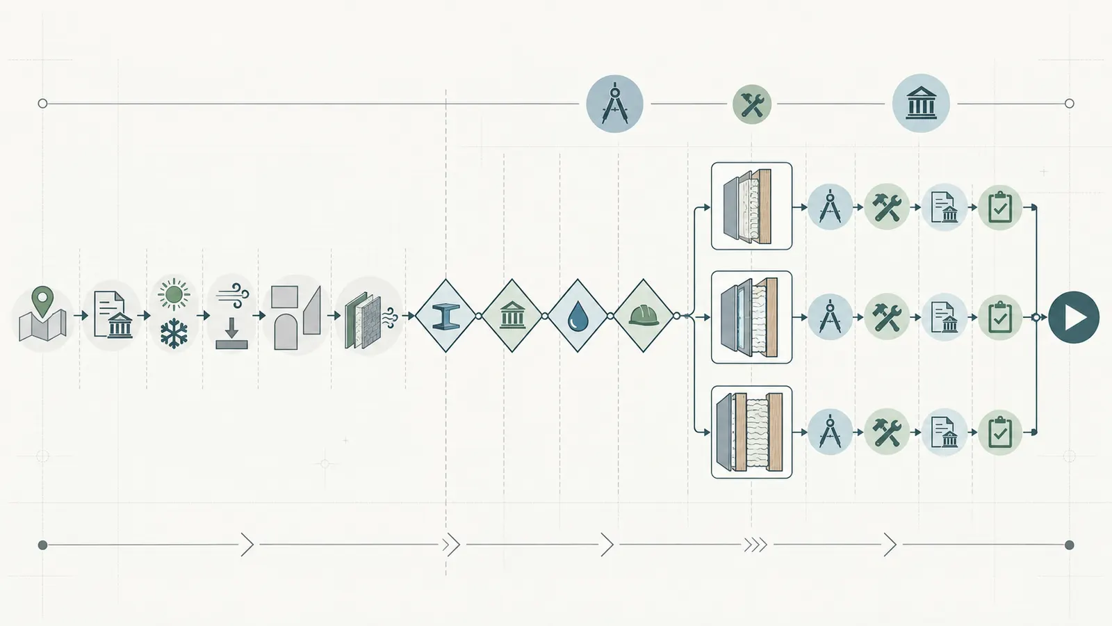
Use the matrix as a gated comparison: first reject any layout that fails structural, code, moisture, opening, or constructability prerequisites; then score the surviving layouts against the homeowner's priorities; finally test the preferred option with explicit dimensions and a labeled illustrative model. The score organizes a conversation and does not replace professional design.
Original contribution: Framing-layout choice matrix and room-by-room freeze worksheet
This is the article's original contribution. Its purpose is to make the design-freeze decision inspectable rather than letting “advanced” or “high R” stand in for a complete wall concept.
Method: collect the project inputs, run the prerequisite gates, score the three complete wall concepts on a 1-to-5 scale against weighted criteria, calculate a simple modeled clear-wall heat-flow comparison, run sensitivity checks, and attach a verification record to the selected concept. The evidence inputs are the APA wall-system overview, DOE advanced-framing guidance, DOE climate-specific assembly guidance, PNNL double-wall guidance, ICC model-code wall topics, and Building Science drainage research.
Limitations: the matrix is not structural engineering, a code approval, a hygrothermal simulation, a contractor bid, a product evaluation, or a measured performance study. The numerical example is illustrative. Local adoption, site loads, geometry, products, workforce, construction sequence, and professional judgment can change the result. A completed worksheet should preserve the assumptions and the person who confirmed each one.
Step 1: Enter the project inputs
Copy this table into the design brief and fill it before scoring.
| Input | Example entry to replace | Unit or record | Why it changes the comparison |
|---|---|---|---|
| Address and AHJ | Example only: project address, city/county, state | Written jurisdiction and permit link | Identifies adopted code, amendments, review, and inspection path |
| Code and compliance path | Example only: adopted residential and energy code, prescriptive or performance | Edition and local amendment record | Prevents a model-code example from being treated as local law |
| Climate and moisture context | Example only: DOE/PNNL climate zone, exposure, indoor humidity assumption | Climate zone plus design assumptions | Drives insulation, vapor, drying, and condensation review |
| Design loads | To be filled by the design team | Wind, seismic, snow, flood, wildfire, and other project data | Can change spacing, bracing, sheathing, connections, cladding, and foundations |
| Conditioned floor area | Illustrative: 2,400 ft² | ft² | Helps compare wall-area and material consequences, not engineering capacity |
| Exterior wall length | Illustrative: 200 linear ft | ft | Sets a consistent normalized comparison |
| Wall height | Illustrative: 8 ft | ft | Converts wall length to gross area and affects stud lengths and transitions |
| Openings | Illustrative: 20% of gross wall area | % and opening schedule | Reduces clear field and increases headers, jambs, flashing, and edge details |
| Finished wall depth limit | To be filled room by room | in | Affects floor area, trim, window returns, cabinets, and exterior projections |
| Insulation target | To be filled by designer | nominal and effective target, with product | Prevents a cavity R-number from being mistaken for whole-wall performance |
| Control-layer locations | To be drawn | wall sections and details | Makes air, vapor, water, and drying paths reviewable |
| Service strategy | Interior cavity, service wall, fur-out, or mixed | annotated plans | Changes penetrations, backing, access, and trade sequence |
| Crew and supply capability | Named builder and framing crew | written scope and exclusions | Advanced and double-stud methods need execution and inspection capability |
| Future backing | Room-by-room list | locations and attachment needs | Prevents later drilling and improvised blocking |
Step 2: Apply hard gates before scoring
Mark each candidate “pass,” “needs redesign,” or “not evaluated.” A candidate cannot win by scoring high if any gate is unresolved.
| Gate | Pass condition | Evidence to attach | If unresolved |
|---|---|---|---|
| Jurisdiction | Actual AHJ, adopted code, amendments, and review path named | Permit or code record and date | Ask the designer or permit professional to verify before choosing |
| Structural | Load path, bracing, openings, connections, and unusual conditions reviewed | Structural plans, notes, schedules, and engineer responsibility | Do not price it as final or remove members in the field |
| Enclosure | Air, vapor, water, insulation, and drying strategy shown at transitions | Annotated wall sections and hygrothermal rationale where needed | Keep both options in design development; do not freeze on nominal R |
| Openings | Window and door sizes, placement plane, flashing, returns, and replacement path coordinated | Opening schedule and details | Rework elevations and room dimensions before procurement |
| Cladding | Attachment, fastener, drainage, flashing, fire, and movement needs fit the wall | Cladding details and product or system requirements | Get the cladding installer or designer into the review |
| Services | Penetrations, service zone, backing, and access are assigned to trades | MEP coordination plan and penetration map | Hold rough-in scope and protect the air barrier |
| Constructability | Framer and key installers have priced the actual details and exclusions | Scope comparison and written assumptions | Treat any cost as an allowance, not a fixed bid |
| Verification | Pre-cover inspection points and records named | Inspection checklist and photo locations | The homeowner cannot verify concealed work after drywall |
Step 3: Score the live criteria
Use 1 for poor fit, 3 for workable with ordinary coordination, and 5 for strong fit. Weight a criterion from 1 to 5 based on the homeowner's priorities. Do not score a hard-gate failure. The table below is a blank reusable worksheet; the entries are prompts, not recommendations.
| Criterion | Weight 1–5 | What to ask | Conventional score | Advanced score | Double-stud score |
|---|---|---|---|---|---|
| Structural fit | 5 | Does the complete layout fit loads, openings, bracing, and connections? | |||
| Local approval confidence | 5 | Has the actual AHJ or design professional confirmed the path? | |||
| Clear-wall thermal goal | 4 | How does the modeled effective wall result compare after bridges and transitions? | |||
| Moisture and drying confidence | 5 | Are air, vapor, water, and drying paths documented for this climate? | |||
| Window and door coordination | 4 | Are unit plane, flashing, returns, trim, and replacement clear? | |||
| Cladding compatibility | 4 | Can the cladding attach, drain, flash, and move as specified? | |||
| Service routing | 3 | Can trades route services without damaging control layers? | |||
| Future backing and access | 3 | Are loads, cabinets, penetrations, and replacement routes documented? | |||
| Crew capability | 4 | Has the named crew built and inspected this exact method or a comparable one? | |||
| Material and schedule risk | 3 | Are materials, tolerances, sequencing, and inspection windows realistic? | |||
| Interior area and geometry | 2 | Does wall depth fit setbacks, rooms, stairs, cabinets, and trim? | |||
| Homeowner priorities | 2 | Does it serve the stated comfort, durability, simplicity, or future-change goal? |
Calculate each column as:
weighted fit = sum of (criterion weight × layout score) / sum of criterion weights
This number is not a building rating. It is a transparent way to show why a layout was preferred. Keep the individual scores and comments; a single average can hide a serious moisture or structural uncertainty.
Step 4: Room-by-room worksheet
The wall method can be right for the exterior wall field and still fail at a room. Complete one line for each room or elevation.
| Room or elevation | Openings and sizes | Service and backing needs | Wall-depth limit | Control-layer or moisture concern | Professional confirmation | Pre-cover evidence |
|---|---|---|---|---|---|---|
| Kitchen | Windows, exterior door, hood or make-up air | Upper cabinets, backsplash, plumbing, appliances | Cabinet and aisle clearances | Penetrations and backsplash transitions | Architect, structural, MEP | Photo before insulation and before drywall |
| Bathroom | Window, exhaust, plumbing wall | Grab bars, accessories, supply and waste lines | Tile build-up, niches, fixtures | High indoor humidity and penetrations | Architect, plumbing, enclosure | Duct, seals, backing, and control-layer photos |
| Bedroom | Egress windows and shades | Headboard, future equipment, receptacles | Trim and furniture clearances | Window sill and air seal | Architect, window installer | Opening and flashing records |
| Living room | Large glazing or doors | TV, shelves, fireplace or equipment | Deep returns and furniture | Large opening, rain exposure, shear segments | Structural, window, cladding | Header, bracing, sill, and flashing records |
| Utility room | Service penetrations and access | Panels, shutoffs, ducts, condensate, filters | Equipment clearance | Air barrier and fire or rated details | MEP and designer | Penetration map and service access record |
| Exterior cladding elevation | Corners, joints, penetrations, decks | Furring, fasteners, lights, hose bibs | Setbacks and projections | Drainage plane, flashing, outlets | Cladding and enclosure professional | Drainage and flashing photo set |
The homeowner's action is to fill the first four columns and identify the questions. The professional's action is to complete the last three. The handoff is complete when the same wall name and detail reference appear in the room plan, wall section, structural set, MEP set, and builder scope.
Step 5: Illustrative clear-wall heat-bridge model
The following is a modeled example, not a measured result, code calculation, energy rating, or product claim. It demonstrates how to make assumptions visible and test sensitivity.
Assume a simplified clear-wall section with parallel heat-flow paths. Inputs:
- conventional and advanced clear wall depth: 5.5 in;
- illustrative insulated-path resistance: R-23 for the 5.5-inch cavity;
- illustrative wood-path resistance: 1.25 per inch × 5.5 in = R-6.875;
- conventional framing fraction: 25%;
- advanced framing fraction: 18%;
- double-stud total insulated depth: 10 in;
- illustrative double-stud insulated-path resistance: R-40;
- illustrative double-stud wood-path resistance: 1.25 per inch × 10 in = R-12.5;
- illustrative double-stud framing fraction: 12%.
For a simple parallel-path model:
U_model = (framing fraction / R_wood path) + (insulated fraction / R_insulated path)
R_model = 1 / U_model
Results:
| Modeled option | Calculation | Modeled U | Modeled R |
|---|---|---|---|
| Conventional | (0.25 / 6.875) + (0.75 / 23) | 0.0688 | 14.5 |
| Advanced | (0.18 / 6.875) + (0.82 / 23) | 0.0617 | 16.2 |
| Double-stud | (0.12 / 12.5) + (0.88 / 40) | 0.0316 | 31.6 |
The arithmetic shows why effective performance can differ from nominal cavity performance, but the inputs are deliberately illustrative. The model ignores corners, plates, headers, window edges, floor lines, fasteners, air leakage, moisture, exterior continuous insulation, thermal bypasses, and thermal bridging in cladding attachments. It should never be used to prove code compliance or choose insulation without the project designer.
Sensitivity is more useful than a single headline. If the double-stud framing fraction rises from 12% to 20% while the other assumptions remain fixed, the model becomes U = (0.20 / 12.5) + (0.80 / 40) = 0.0360, or R_model ≈ 27.8. If the assumed double-stud insulated path falls from R-40 to R-30 at the original 12% framing fraction, then U = (0.12 / 12.5) + (0.88 / 30) = 0.03893, or R_model ≈ 25.7. The direction is the point: more framing or less insulation reduces the modeled benefit, and neither variation addresses moisture or window details.
Illustrative material-efficiency check
Use a normalized wall length to discuss framing quantity without pretending to price a project. Assume 100 linear ft of straight wall, 8 ft high, and ignore openings, corners, plates, headers, blocking, waste, and bracing. Approximate stud positions as ceiling(wall length / spacing) + 1:
- 16-inch spacing:
ceiling(100 ft / (16/12 ft)) + 1 = 76 positions; - 24-inch spacing:
ceiling(100 ft / 2 ft) + 1 = 51 positions; - two 24-inch frames:
51 × 2 = 102 positions.
At 8 ft per position, the normalized vertical stud footage is 608 linear ft for the single 16-inch frame, 408 linear ft for the single 24-inch frame, and 816 linear ft for two 24-inch frames. This does not say that advanced framing is cheaper or that double-stud framing is wasteful. It shows why the material question must include plates, headers, corners, blocking, sheathing, furring, insulation, labor, waste, openings, and the value of the service zone. DOE's historical studies report savings in particular homes and production contexts, but those results are not a bid for this home. See the DOE program profile for its bounded historical context.
The next decision is to ask the estimator for a line-item comparison with identical wall length, opening schedule, cladding, window package, sheathing, insulation, service scope, waste assumptions, labor sequence, and inspection scope. If one price excludes the additional window returns or cladding attachment, it is not a comparable price.
6. Sequence design freeze, pricing, permitting, and field verification #
Freeze the wall only after the design team has completed a sequence of responsibility handoffs: homeowner brief, jurisdiction and loads, structural concept, enclosure concept, openings and cladding, services and backing, constructability and price, permit review, then pre-cover verification. A late wall-method change can alter room sizes, window orders, foundation edges, roof overhangs, cladding quantities, and trade scopes.
Gate A: establish the decision record
The homeowner owns the desired outcomes and accepts the cost, area, comfort, durability, and future-change tradeoffs. Write a one-page decision record with:
- the project address and jurisdiction;
- the adopted code and energy-compliance path, with source and date;
- the design climate and site conditions;
- the homeowner's reasons for considering advanced or double-stud framing;
- the unacceptable outcomes, such as lost interior area, unresolved moisture risk, or unavailable crew capability;
- the target wall depth range;
- the target window and cladding families;
- the service and future-backing strategy;
- the professional responsible for structural confirmation;
- the professional responsible for enclosure and condensation-control confirmation;
- the proposed inspection and photo records.
Do not use a generic internet “best wall” as the decision record. It cannot name the local AHJ, loads, openings, trade sequence, or responsibility for the actual home.
Gate B: issue two or three complete wall concepts
The architect or designer should issue comparable sections at a straight wall, outside corner, inside corner, interior wall intersection, floor line, roof line, window head, window sill, exterior door, deck or porch connection, and major service penetration. The structural designer should overlay the load path and framing schedule. The enclosure professional should mark air, vapor, water, insulation, and drying paths. The builder should annotate tolerances, sequence, and material availability.
The concepts should name assumptions instead of hiding them. “2x6 advanced” is incomplete. “2x6 studs at 24 inches on center, aligned with trusses, two-stud corners, insulated headers where permitted, specified sheathing and bracing, exterior weather-resistive barrier, drained cladding, interior service cavity, and opening details D-401 through D-408” is reviewable. “Double-stud wall” is incomplete. “Exterior structural 2x6 line, 3-inch separation, interior 2x4 service line, continuous air barrier at [named plane], vapor-control strategy for [named climate], insulation type and density, window plane, floor-line transition, and cladding attachment detail” is reviewable.
Gate C: compare scope and constructability
Ask the builder or estimator to return a scope matrix, not just three totals.
| Scope item | Conventional | Advanced | Double-stud | Who confirms |
|---|---|---|---|---|
| Framing lumber and cutting | Include all plates, openings, corners, blocking, and waste | Identify reduced members and extra layout or backing | Include both frames, separation, ties, and special transitions | Builder and estimator |
| Sheathing and bracing | Name panels and fastening | Show panel edges at wider spacing and bracing exceptions | Identify which line is structural and how the other is supported | Structural designer and builder |
| Insulation | Product, thickness, installation, and bridge assumptions | Same, including headers, corners, intersections | Full cavity fill, density or support, settlement control, and transitions | Enclosure professional and insulation installer |
| Air and vapor control | Plane, seams, penetrations, inspection | Plane around reduced framing and service routes | Plane between or outside frames, climate-specific rationale | Enclosure professional |
| Windows and doors | Installation plane and returns | Same with reduced opening framing | Deep returns, support, flashing, trim, and replacement path | Architect and window installer |
| Cladding | Attachment and drainage | Fastening at actual spacing and furring | Fastener length, furring, cavity, and outlets | Cladding professional |
| Services and backing | Penetrations and backing | Grid, corners, boxes, cabinets | Service wall, access, no-penetration map | MEP and interior teams |
| Inspection | Framing, sheathing, weather barrier, insulation, air seal | Additional reduced-framing and backing checks | Two frames, cavity fill, control layer, and deep openings | Builder, inspector, and designer |
If the builder cannot price a line because the detail is unresolved, mark it as an allowance with an owner and due date. Do not move to procurement on the basis of a low total that omits the unresolved scope.
Gate D: permit and professional review
The design professional or permit professional submits the named project documents to the actual AHJ. The homeowner should retain the approved drawing set, comments, responses, and any accepted alternate-method or engineered-design record. A model-code link, a product brochure, or an online article cannot substitute for the permit record.
The DOE advanced-framing guide recommends consulting local building officials early because some techniques may not be allowed under certain wind, seismic, or local conditions. Follow that early-review principle. For a double-stud option, include the wall section, air-barrier and vapor-control strategy, insulation specification, and any requested compliance analysis. PNNL's brief explains why a double wall needs a documented plan-review and field-inspection approach rather than an assumption that its extra cavity is automatically compliant. See the PNNL compliance brief.
Gate E: verify before insulation and drywall
The most useful homeowner verification window is after framing, sheathing, weather-control work, windows, rough services, and air-sealing work are visible but before insulation and drywall hide them. The homeowner can attend and record; qualified professionals must perform or sign off on professional inspections.
Use this field checklist:
- Confirm the installed wall label, stud spacing, wall depth, openings, corners, intersections, plates, headers, posts, blocking, and structural connectors against the approved drawings.
- Confirm that the braced wall and shear elements, sheathing orientation, joints, fasteners, straps, hold-downs, and required nail lines are installed as documented.
- Confirm the window and door rough openings, sill support, installation plane, flashing, end dams, head flashing, and outward drainage path.
- Confirm the water-resistive barrier or drainage plane laps and penetrations, the drainage cavity or gap where specified, and the lower outlets or weeps.
- Confirm the continuous air-control layer and sealed seams at plates, corners, intersections, windows, doors, and service penetrations.
- Confirm the vapor-control strategy is installed at the specified plane for the project's climate and code path; do not substitute a different membrane because it is available.
- Confirm insulation type, depth, support, density where applicable, and contact with the intended air barrier; record gaps, compression, voids, and areas blocked by framing.
- Confirm service routing, backing, access panels, shutoffs, and no-penetration zones.
- Photograph each representative detail with a room, grid, elevation, and drawing-detail reference.
- Record unresolved items, responsible trade, due date, and the retest or reinspection needed before cover.
PNNL's double-wall guidance specifically calls for fully filling the cavity without misalignments, compression, or voids and for selecting control layers according to wall type and climate. Use those items in the pre-cover check. Building Science's drainage research explains why the record must include outlets and drying paths, not just a photo of a membrane. Use the drainage components as photo subjects.
Remote-assessment limits
Photos, video calls, plan screenshots, and homeowner measurements can identify missing documents, inconsistent wall labels, visible gaps, water stains, blocked outlets, and obvious scope conflicts. They cannot reliably confirm concealed fastening, structural capacity, air leakage, moisture content, fire or rated assemblies, code compliance, or the full condition of a wall after it is covered. Do not open, climb, enter a confined space, remove structural members, work near live electrical parts, or perform a high or fall-exposure inspection to answer this comparison. Arrange the appropriate qualified professional and follow the AHJ's inspection requirements.
Photos, video, and homeowner measurements also cannot diagnose water, gas, hydronic, or other pressure hazards, and they cannot diagnose mold, asbestos, lead, or other contamination. If a remote review or visible condition suggests a leak, pressurized line, unknown service, suspected contamination, or contaminated dust or material, stop work, keep people away, and do not open, cut, drill, sample, clean, or otherwise disturb it. Use the appropriate qualified professional—such as the responsible plumber, gas professional, hydronic professional, utility, industrial hygienist, or licensed asbestos or lead professional—and follow emergency guidance and the requirements of the actual AHJ. The homeowner's safe role is to preserve the observation, location, date, and documents for that handoff.
The next decision after pre-cover verification is not whether the wall “looks good.” It is whether each unresolved item has been corrected, inspected or tested by the responsible professional, and entered into the closeout record before the next layer makes it inaccessible.
7. Use failure branches to make the final choice #
Choose the layout that the named team can specify and verify under the project's real constraints; if a structural, moisture, opening, cladding, or service question remains unresolved, keep the design open and resolve that question before freeze. The following branches are prompts for the next professional conversation, not diagnoses or permission to alter work.
| What you observe | What it may mean | What not to infer | Safest next step |
|---|---|---|---|
| Engineer cannot show a continuous load path at an offset roof or floor | The layout needs a transfer, post, beam, connector, or revised geometry | A second stud line automatically fixes the load | Ask for a marked-up structural section and revised calculations or details |
| Large glazed wall leaves short wall segments | Bracing and opening transfer may control more than cavity depth | More insulation can compensate for missing shear or bracing | Have the structural designer review the opening, bracing, and connection design |
| Project has high wind, seismic, snow, or unusual exposure | A reduced-framing technique may need changes or engineering | “Advanced framing” is accepted everywhere because it is a DOE technique | Confirm the actual AHJ and design conditions before selecting the method |
| Builder says 24-inch spacing is advanced framing but has no corner, opening, or backing plan | Only one attribute was selected | Spacing alone delivers the full thermal or material benefit | Request the complete framing schedule and detail set |
| Double-stud sketch shows more cavity but no air or vapor plane | Moisture control is unresolved | A thick insulated wall is automatically durable | Hold the choice and obtain a climate-specific control-layer and drying review |
| Wall section stops at the cladding face | Window, flashing, furring, fasteners, and drainage may be missing | A weather-resistive barrier alone proves water control | Require representative window, base, corner, and roof-wall sections |
| Window installer says the unit can be “made to work” after framing | Installation plane, support, flashing, or replacement access may be unresolved | A rough opening is enough to order the window | Freeze the unit, plane, sill/head/jamb details, and responsibility before order |
| Electrical or plumbing rough-in crosses the planned air barrier | Sealing, inspection, and drying details may be lost | Drywall or insulation will hide the problem safely | Mark the penetration, assign the sealing trade, and inspect before cover |
| Cabinet, grab-bar, or equipment backing is absent | Future attachments may rely on improvised or weak fastening | A nearby stud is close enough for every load | Issue the room-by-room backing plan and install it before insulation or drywall |
| Estimate is lower for one option but omits special openings or cladding attachment | Prices are not equivalent scopes | The lower total is the true lifecycle cost | Reissue an apples-to-apples scope matrix with allowances shown |
| Crew has not built the proposed method | Tolerances, sequence, and inspection evidence may be less predictable | Familiarity will appear automatically on site | Ask for a method statement, mock-up, training, or a different wall concept |
| Insulation has voids, compression, settlement risk, or inaccessible pockets | Effective performance and control-layer continuity may be below design | Nominal R-value on the invoice proves installation quality | Stop cover, document locations, and have the responsible installer correct and verify |
| Permit approval exists but field details differ | Approved documents may not match the installed assembly | Permit approval proves construction quality | Request an as-built review and AHJ or design-professional direction |
When conventional is the responsible choice
Select the conventional baseline when it meets the project's effective thermal, durability, structural, and space requirements and the alternatives introduce unresolved coordination or crew risk. This is not a failure of ambition. A simpler wall that is fully documented, correctly flashed, air-sealed, insulated, inspected, and maintainable can outperform a nominally higher-performing wall that is improvised at openings and transitions.
Conventional is especially worth retaining as a price and execution baseline when the plan is irregular, openings are numerous, local trades are unfamiliar with reduced framing, the cladding has demanding attachment requirements, or the project schedule cannot support a new method. Keep any exterior continuous insulation, service cavity, or other thermal strategy as a separate coordinated option rather than assuming the stud line alone must solve every goal.
When advanced is the responsible choice
Select advanced framing when the structural designer can show the load path, the geometry supports a regular grid, the enclosure details maintain continuous insulation and control layers, the window and cladding interfaces are complete, and the actual crew accepts the framing, backing, and inspection requirements. DOE describes advanced framing as a family of techniques intended to reduce lumber and waste and can improve thermal performance by reducing thermal bridging, but its guidance also calls for early local review. Use the DOE guide as the bounded method reference.
The decision record should name which techniques are actually used. For example: 24-inch stud spacing in selected walls, aligned roof and floor members, two-stud corners, insulated headers where allowed, reduced opening framing, drywall backing clips or ladder blocking, and the exceptions at shear walls, high-load openings, cabinets, fixtures, and cladding joints. “Advanced throughout” is less useful than a schedule that identifies every exception.
When double-stud is the responsible choice
Select double-stud framing when the project has a clear need for added wall depth, insulation, service routing, or reduced clear-field thermal bridging and the team can detail and verify the control layers, openings, floor lines, cladding, and construction moisture. PNNL describes double walls as deep insulated cavities and emphasizes complete cavity fill plus climate-dependent air and vapor control. See the PNNL double-wall guidance.
Do not select it as a universal answer to a high R-value target. Its cost and area consequences include a thicker wall, smaller rooms or larger footprint, deeper window and door returns, longer fasteners or furring, more framing or insulation labor, more complex transitions, and potentially more material storage and sequencing. Its moisture risk depends on the exact layers and climate; the DOE's monitored 5A case study is evidence that thick-wall assemblies merit moisture analysis, not evidence that every double-stud wall will behave the same way. Read the DOE case-study boundary.
The final freeze record
At the end, write one paragraph that a homeowner, builder, designer, inspector, and future owner can all read:
“For [project address and AHJ], the project team selected [layout name and exact framing schedule] because it passed [structural, climate/enclosure, opening, cladding, service, crew, and future-backing gates]. The structural load path is shown on [drawing references]. The air-control plane is [location], vapor-control approach is [location and rationale], water-control and drainage path are [details], insulation is [type and installed depth], and windows/cladding/services are coordinated at [detail references]. The builder will verify [pre-cover records] before [insulation/drywall/cladding]. The unresolved items are [list], owned by [names or roles], due by [date].”
Attach the matrix, the modeled assumptions, professional comments, permit records, scope comparison, marked-up details, and pre-cover photos. Record the substantive review date when the decision is actually checked, not merely when the page is republished.
If you need adjacent homeowner guidance before freezing the wall, use Brictale's homeowner guide feed to find currently published planning, materials, and construction decisions. The wall choice is complete when the next professional can act from the same documents without guessing which framing, control layer, opening, or service strategy you meant.
Cite this guide
Brictale. “How to Compare Conventional, Advanced, and Double-Stud Wall Framing Before Design Freeze.” Published 2026-10-07; updated 2026-10-07.
https://brictale.com/build/materials/compare-conventional-advanced-double-stud-wall-framing · Read the Markdown version
Original contribution: Framing-layout choice matrix and room-by-room freeze worksheet. A reproducible comparison that links conventional, advanced, and double-stud wall framing to load paths, thermal bridging, insulation depth, services, openings, cladding, inspection evidence, and future changes.
Sources and scope
Evidence behind this page
- APA describes exterior walls as critical structural components and its wall guide covers wood structural panel sheathing, wall bracing, shear walls, combined shear and wind uplift, advanced framing, and force transfer around openings; the guide is an overview for architects, engineers, builders, and designers rather than a project-specific design.
Engineered Wood Construction Guide: Wall Construction — APA
APA wall-construction guide overview; use for structural topics, sheathing, bracing, openings, and advanced-framing context, not for a specific site's design loads or local approval.
Accessed · Link to this claim - The U.S. Department of Energy's Advanced Wall Framing guide describes techniques including two-foot modular planning, studs up to 24 inches on center, two-stud corners, aligned framing, and selected single headers or top plates, while warning that some techniques may not be allowed under certain high-wind, seismic, or local conditions and should be discussed with local building officials early.
Advanced Wall Framing — U.S. Department of Energy Building America
DOE Building America technical guide; methods and cautions are general U.S. guidance, not a substitute for the named project's adopted code, amendments, or structural design.
Accessed · Link to this claim - DOE Building America reports that reducing framing can replace some lumber with insulation, reduce thermal bridging, and improve wall thermal performance; its historical field and study results are program evidence, not a promise of a fixed savings percentage for a new project.
Building America Top Innovations: Advanced Framing Systems and Packages — U.S. Department of Energy
DOE Building America program profile summarizing historical studies and field work; do not transfer its reported percentages or costs to an individual home without project analysis.
Accessed · Link to this claim - DOE's Building America climate-specific guidance points to a 2021 IECC Climate-Specific Building Assemblies Tool that uses county or ZIP climate-zone lookup and shows wall and other assemblies intended to meet 2021 IECC and IRC thermal-efficiency and condensation-control requirements; the tool does not establish what a particular city or county has adopted.
Building America Climate-Specific Guidance — U.S. Department of Energy
DOE/PNNL climate-specific guidance and linked assembly tool; use for climate-zone orientation and assembly research, then verify the project's actual jurisdiction and adopted code.
Accessed · Link to this claim - The 2021 International Residential Code wall-construction text ties sheathing and wall framing to wind pressures, table conditions, bracing, stud spacing, openings, and other design limits; it is a model-code reference and does not by itself prove that a local jurisdiction has adopted the 2021 IRC without amendments.
2021 International Residential Code, Chapter 6: Wall Construction — ICC
ICC online 2021 IRC Chapter 6; model-code text for understanding the kinds of limits that affect wood wall design, not a local permit determination.
Accessed · Link to this claim - The Building America Solution Center describes double-stud construction as two stud-framed walls forming a deep cavity for insulation and requires the air-control and vapor-control layers to be selected and detailed based on the double-wall type and climate zone; it also calls for insulation without gaps, compression, or voids.
Double Walls for More Insulation — Building America Solution Center, PNNL
PNNL Building America Solution Center installation guidance; use for assembly coordination and field-verification questions, not for approving a specific wall without project details.
Accessed · Link to this claim - PNNL's double-wall code-compliance brief says double-stud framing is not specifically addressed as a system in the IRC or IECC, while insulation, moisture, and air-leakage compliance still must be reviewed and the wall's air barrier and vapor-retarder strategy must be documented; its examples are tied to cited code editions and climate zones.
Double Wall Framing — Code Compliance Brief, Building America Solution Center
PNNL code-compliance brief; code-edition and climate-zone examples are not a national rule and must be rechecked against the project's adopted code and amendments.
Accessed · Link to this claim - Building Science's drainage research identifies five components of a functional drained wall: a rainscreen or cladding screen, drainage plane or capillary break, drainage gap or cavity, flashing that directs water outward, and weep or drain holes.
Building Science research report on lightweight cladding systems and drainage, storage, and drying; exact cladding details and required gaps remain project- and product-specific.
Accessed · Link to this claim - The same Building Science report explains that drainage does not remove all water that enters behind cladding, retained moisture can remain in surfaces and materials, and ventilation or other drying mechanisms can matter; its laboratory test protocol is not a universal construction-performance guarantee.
Building Science report abstract, background, research scope, and test discussion; use to explain moisture-control limits, not to prescribe one gap size for every cladding or climate.
Accessed · Link to this claim - Building Science's durable-home report describes a systems-engineering approach in which structural requirements, water and vapor management, material durability, and energy efficiency are considered together; the report is a post-Katrina New Orleans case context, not a universal coastal design specification.
2007 Building America report for post-Katrina New Orleans; use for systems-coordination reasoning and regional-limit reminders, not as a current local code or product specification.
Accessed · Link to this claim - A DOE Building America case study monitored a double-stud cellulose wall in IECC Climate Zone 5A with temperature, relative-humidity, and moisture-content sensors, and explains that thicker walls can increase the need to understand moisture behavior; the monitored assembly and climate cannot be generalized to every double-stud design.
DOE Building America case study of one monitored double-stud assembly in Massachusetts Climate Zone 5A; use for the need to evaluate moisture risk, not as a universal performance result.
Accessed · Link to this claim - DOE's Building Science Education guidance says advanced framing at window and door openings should limit king studs, jack studs, and cripple studs to what the structural and spacing requirements need, because unnecessary framing consumes cavity space and creates thermal bridges.
Framing: Building a Wall: Door Framing with Advanced Framing — DOE Building Science Education
DOE educational framing guidance; use as a design-review question and coordinate the actual opening schedule with the structural designer and local code.
Accessed · Link to this claim