What MERV Filter Is Safe for a Ducted Heat Pump Without Losing Airflow?
Compare MERV 8, 11 and 13 for a ducted heat pump using filter fit, pressure-drop data and airflow verification—not a universal rating.
The short answer
For a ducted heat pump, choose MERV 13 only when the installed air handler, filter slot and fan can accommodate it. Otherwise use the highest rating the equipment documentation or a qualified HVAC professional verifies. Match the exact dimensions, seal the slot, follow the airflow arrow, record the installation date, and stop if comfort, noise, icing or airflow changes appear.What MERV Filter Is Safe for a Ducted Heat Pump Without Losing Airflow?
For a ducted heat pump, choose MERV 13 only when the installed air handler, filter slot and fan can accommodate it. Otherwise use the highest rating the equipment documentation or a qualified HVAC professional verifies. Match the exact dimensions, seal the slot, follow the airflow arrow, record the installation date, and stop if comfort, noise, icing or airflow changes appear.
This is a United States homeowner buying and maintenance guide for an existing ducted air-source heat pump connected to forced-air ductwork. It does not cover ductless mini-splits, designing a filter cabinet before construction, refrigerant work, or a universal promise that MERV 8, 11 or 13 is safe in every home. A ducted heat pump is in scope because it uses conventional forced-air ductwork; a ductless mini-split is a different equipment path and does not use that ductwork, as ENERGY STAR's air-source heat-pump overview explains.
The practical decision is not “Which number is best?” It is “Which exact replacement filter gives the particle control I need while staying within the installed system's documented or verified airflow and pressure limits?” That requires a few inputs: equipment model, filter location, nominal and actual dimensions, depth, current rating, candidate rating, published pressure-drop data if available, slot sealing, household particle goal, and a plan for checking the result after installation. The worksheet in this article makes those inputs visible so a professional can verify the unresolved ones without starting over.
1. Choose the highest MERV your complete forced-air system can support #
The safest general answer is conditional: EPA recommends MERV 13, or as high a rating as the system fan and filter slot can accommodate. The heat-pump label alone cannot establish that limit. If your manual gives a permitted filter rating or pressure-drop limit, follow it. If the manual is silent, the filter is unusually thick or restrictive, the slot is damaged or leaky, or system performance changes after the installation, ask a qualified HVAC professional to verify airflow and static pressure before continuing with a higher-efficiency filter. EPA's ducted heat-pump guidance makes the system-level boundary explicit.
What “safe” means in this decision
Here, “safe” has four separate meanings. A filter can be physically safe to handle yet unsuitable for the equipment. It can fit the slot but cause excessive resistance. It can provide a high rating but leak around its edges, sending unfiltered air around the media. Or it can work when new and become too restrictive when loaded with dust. Treat those as four gates rather than one label:
| Gate | Question to answer | Homeowner evidence | Stop or handoff condition |
|---|---|---|---|
| Equipment | What indoor unit and fan are actually moving the air? | Model and serial photos, manual, heat-pump and air-handler names | No model information, altered equipment, or conflicting manuals |
| Geometry | Does the replacement fit the real rack without bending, crushing or leaving a bypass path? | Nominal label, actual dimensions, depth, slot and gasket observations | Filter bows, rattles, binds, leaves a gap, or requires force |
| Airflow | Can the fan move the required air against this filter and the rest of the system? | Manual limit, manufacturer pressure-drop data, professional measurement | Unknown limit plus a proposed higher-resistance filter; new noise, weak registers, icing or abnormal operation |
| Maintenance | Will the filter be inspected and replaced before loading becomes a problem? | Installation date, visual condition, runtime and particle events | Filter is inaccessible, forgotten, wet, damaged or visibly loaded |
The four gates matter because filtration and comfort are coupled. The filter sits in the return airstream. Resistance at that point changes the pressure the blower must overcome. The rest of the system—return grille, return duct, coil, supply duct, registers, dampers and any other accessories—also consumes the fan's available pressure capability. A new filter cannot be judged in isolation from those parts.
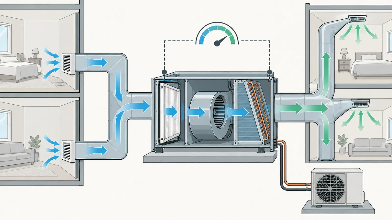
The word “MERV” itself is also narrower than many package claims imply. EPA defines MERV as a rating derived from an ASHRAE test method for capture of specified particle-size ranges. A higher MERV indicates better capture in the tested ranges; it does not tell you the exact resistance of one product, the clean-air delivery of your house, the condition of your ductwork, or whether the filter is installed without bypass. It is a comparison input, not a complete compatibility certificate.
The default path for a homeowner
Use this sequence when you want to replace a routine filter and have no symptoms of a system problem:
- Confirm that the system is ducted and identify the indoor air handler or furnace cabinet. Look for one filter location, or document every location if there are multiple return grilles. Do not assume that a filter in a wall grille is the only filter in the system.
- Photograph the equipment nameplate, the current filter label and the filter rack before removing anything. Record the current nominal size, actual dimensions if printed, depth, MERV rating, airflow arrow and installation date if known.
- Read the indoor-unit installation and operation manual. Search for “filter,” “airflow,” “external static pressure,” “pressure drop,” “minimum airflow,” “maximum airflow,” “blower,” and “warranty.” Save the exact page or model-specific document.
- Choose a candidate with the same required dimensions and orientation. Prefer a candidate whose manufacturer publishes pressure-drop data for the exact size, depth and airflow. Do not substitute a marketing phrase such as “maximum filtration” for pressure-drop data.
- If the manual or manufacturer data confirms the candidate, install it with the arrow pointing in the actual airflow direction, then verify the slot is closed and sealed.
- Record baseline observations and post-installation observations. If you cannot establish compatibility, use the highest previously verified rating and hand the record to an HVAC professional.
This path does not tell every homeowner to buy MERV 13. It gives MERV 13 priority when the system can take it, consistent with EPA's conditional recommendation. It also leaves room for a different choice when the installed system, filter geometry, household goal or evidence says the tradeoff is not acceptable.
2. Identify the actual air-moving system before comparing filters #
The filter belongs to the ducted forced-air assembly, not to the outdoor heat-pump nameplate. Before comparing MERV ratings, identify the indoor air handler, return path, filter rack, fan control and any backup heat or accessory that shares the airstream. That equipment record determines who can verify compatibility and which document controls the decision.
Ducted and ductless are different decisions
A ducted air-source heat pump typically has an outdoor unit, an indoor air handler or coil cabinet, a blower, return ductwork and supply ductwork. Depending on the installation, backup electric resistance heat or a dual-fuel furnace may be integrated with the indoor equipment. All of those components may affect airflow and operating modes. The filter may be at a return grille, in a filter box attached to return ductwork, or at the inlet of the indoor equipment. Trane lists those common filter locations, but its list is not a substitute for looking at your installation.
A ductless mini-split has a different indoor-unit arrangement and is excluded from this guide. Do not use the conclusions here to select a replacement screen, washable mesh or accessory for a wall-mounted ductless head. The question supplied for this page is about a ducted air-source heat pump and its forced-air filter assembly.
Build the equipment record
The responsible homeowner task is identification, not diagnosis of refrigerant or electrical performance. With the system off, collect:
- Indoor equipment manufacturer and complete model number.
- Outdoor heat-pump manufacturer and model number, if different.
- Air-handler, furnace or coil cabinet model, including any suffixes.
- Filter location or locations and whether filters are in series or at separate returns.
- Filter dimensions printed on the old filter: nominal width, height and depth.
- Actual filter dimensions if the manufacturer publishes them, plus your measured slot dimensions.
- Current filter MERV claim, brand, product line and any pressure-drop chart.
- Fan setting, if visible to you without opening electrical panels.
- Thermostat mode and whether the system has backup heat, zoning or a variable-speed control.
- Date of the last professional maintenance visit and any previous filter-related symptoms.
Do not remove an electrical panel to find a fan model or test voltage. Do not open refrigerant circuits. A homeowner can photograph labels and manuals; electrical testing, refrigerant diagnosis, blower adjustment and pressure measurements belong to a qualified local HVAC professional. Carrier's service guidance distinguishes basic filter care from professional airflow, electrical and refrigerant checks.
Determine who owns each unknown
Assigning responsibility prevents the common handoff failure in which a homeowner buys a filter and assumes the installer has approved it. Use this division:
| Input or action | Homeowner can usually collect | Installer or HVAC professional should verify when unresolved |
|---|---|---|
| Model and serial labels | Photograph and transcribe | Resolve illegible or conflicting model numbers |
| Nominal filter size | Read the old filter and package | Confirm the rack's required dimensions if the old filter was wrong |
| Actual fit and gasket condition | Inspect with the system off | Repair, replace or modify a damaged rack |
| MERV claim and exact product | Read the label and keep the package | Confirm whether a different product has acceptable resistance |
| Pressure-drop data | Request the manufacturer's chart | Compare data at the installed airflow and operating condition |
| Minimum airflow or maximum static pressure | Find the manual's specification | Measure or calculate system performance with instruments |
| Fan speed, controls and coil condition | Report symptoms and settings you can see | Test, adjust or repair equipment |
| Warranty language | Locate the written warranty | Interpret model-specific terms with the manufacturer or dealer |
| Local requirement | Identify the property jurisdiction | Ask the authority having jurisdiction or licensed professional about alterations |
The person who sells a box of filters is not automatically the person who has verified the air handler. A filter manufacturer can publish product data; an equipment manufacturer can publish limits; the local HVAC professional can verify the installed combination. Keep those roles separate in your record.
Use the manual as a control document
The installed indoor-unit manual is more important than a general statement on a retailer page. Locate the filter section and look for a required size, maximum depth, recommended filter type, airflow table, external static-pressure limit, fan table, replacement interval or warning about accessories. If the manual references a separate service or installation document, obtain that document for the exact model.
Do not infer approval from the fact that the filter slides in. A rack can accept a filter physically while the fan cannot maintain required airflow. Do not infer disapproval from a higher MERV number alone either: filters of the same MERV can have different resistance, and deeper media can have more filtration area. The correct next step when the manual is silent is comparison of the exact product data and, if needed, professional measurement—not a guess based on the outdoor unit's tonnage or brand.
3. Measure fit, dimensions and bypass before buying a higher rating #
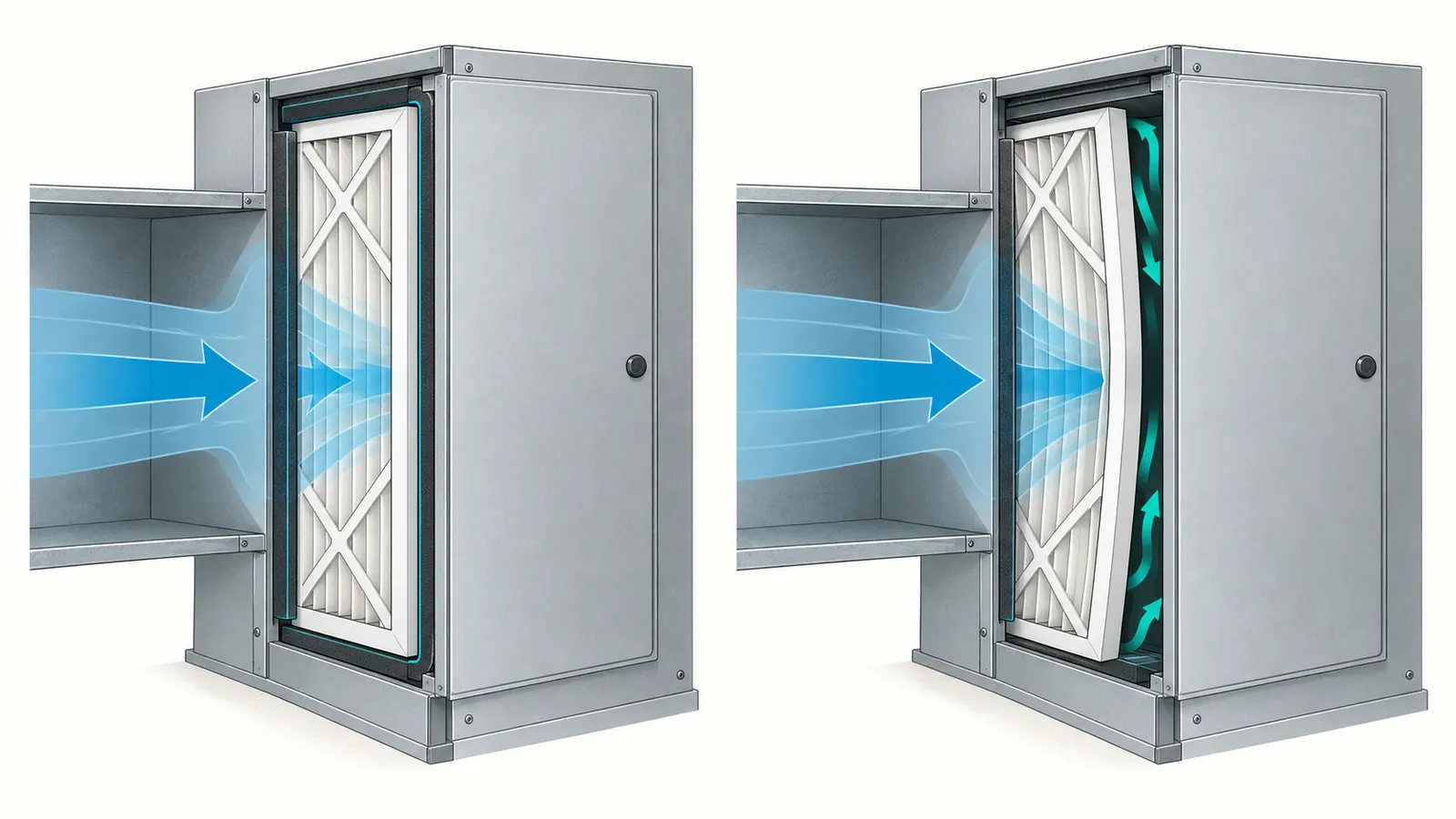
The replacement must fit the rack in all three dimensions, sit in the intended airflow direction, and close the bypass paths without bending or crushing the media. Record both the nominal label and the actual product dimensions; use the rack and manual to resolve conflicts. A high MERV filter that leaks around its edges may deliver less useful filtration than a lower-rated filter that is correctly fitted and sealed.
Nominal size is a shopping shorthand, not a measurement
Filter packaging commonly uses a nominal expression such as width × height × depth. The printed nominal size may not equal the measured outside dimensions. Manufacturers can use different actual dimensions for products sold under the same nominal size, and an old filter may itself be the wrong replacement. Record what the old filter says, then measure the opening and the old filter with a rigid ruler or tape measure while the system is off.
For a rectangular filter, record:
| Field | Unit | What to record | Why it matters |
|---|---|---|---|
| Nominal width | inches | Package or old-filter label | Search and purchasing identifier |
| Nominal height | inches | Package or old-filter label | Search and purchasing identifier |
| Nominal depth | inches | Package or old-filter label | Rack clearance and media configuration |
| Actual width | inches | Product specification or measurement | Prevents binding and bypass |
| Actual height | inches | Product specification or measurement | Prevents binding and bypass |
| Actual depth | inches | Product specification or measurement | Prevents panel interference and air leakage |
| Slot opening | inches | Clear opening, not exterior cabinet size | Determines usable fit |
| Seal or gasket | yes/no plus condition | Compression, tears, gaps, hardened material | Reduces bypass |
| Arrow direction | arrow toward equipment? | Confirm against actual airflow | Prevents reversed installation |
Do not force a filter that is deeper than the rack. Do not flatten pleats to make a filter fit. Do not fold a filter, cut the frame, remove a gasket or wedge loose material into a gap. If a larger filter cabinet is desired, that is a system alteration; it is not a routine filter swap and should be designed and installed by an HVAC professional.
Check the airflow arrow, not just the cabinet orientation
Airflow usually travels from occupied rooms through return grilles and ductwork toward the indoor equipment, then across the filter before the blower or coil, but the exact order depends on the assembly. Follow the arrow printed on the filter and compare it with the equipment manual. Trane's replacement procedure says to install a correctly sized filter with the airflow arrows pointing toward the furnace or air handler.
A reversed filter may still slide into place, which makes this an easy failure to miss. The frame can look correct while the media, support grid or electrostatic layer is oriented incorrectly. If the old filter's arrow conflicts with the manual or the observed return path, stop and ask the installer or a local HVAC professional to identify the direction. Do not use a guessed arrow to resolve an uncertain duct layout.
Inspect the rack and the closed panel
With the system off, look for a continuous seat around the filter frame. The filter should not rattle when the blower starts, bow into the airstream, or leave a visible strip of daylight around the edges. Inspect the access panel and its gasket. A slot attached to the air handler needs to close firmly enough that air cannot simply enter around the media. EPA's Indoor airPLUS technical bulletin calls for an appropriately sealed return-side filter slot, and the broader EPA technical summary on residential air cleaners explains why bypass reduces the effectiveness of a duct-mounted filter.
Do not seal a removable filter access panel with permanent adhesive or expanding foam. The homeowner must be able to replace the filter, and the professional must be able to service the equipment. If a gasket is missing, the frame is bent, screws are stripped, or the panel cannot close without force, record that condition and hand it off. The safest next decision is to restore the rack and seal before evaluating a higher-efficiency filter; otherwise the comparison mixes filter performance with a known installation defect.
A simple bypass observation is not an airflow test
You can observe an obvious gap, whistling edge or displaced filter. You cannot establish the total pressure drop, delivered airflow or refrigeration performance by placing your hand over a register. A strong-feeling register in one room does not prove that every branch has adequate flow. A quiet system does not prove that airflow is correct. A smart thermostat's runtime estimate does not measure static pressure.
Use observations to decide whether to stop, not to claim that the system passed. If the filter visibly bows inward, if the access panel whistles, or if the system sounds materially different after a candidate is installed, return to the previously verified filter if that can be done safely and contact a professional. Keep the candidate's packaging and data sheet for the handoff.
4. Compare MERV, filter construction and pressure drop as separate inputs #
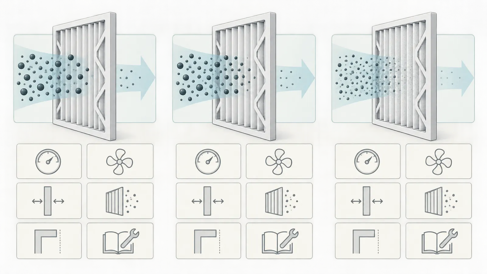
MERV compares tested particle-capture performance; pressure drop describes resistance at a stated airflow; thickness and pleat area influence the pressure drop of a particular product. Compare all three for the exact filter, because the same MERV rating does not establish the same airflow effect. ASHRAE advises evaluating the air-distribution system before higher-efficiency filters and checking airflow both with a new filter and near replacement condition. The ASHRAE residential space-conditioning guidance also directs readers to the equipment manufacturer's minimum airflow and maximum static-pressure information.
Read the MERV number correctly
MERV is useful because it gives a standardized way to compare capture in particle-size bands. It is not a direct percentage of every particle in your home, and it is not a health outcome. EPA's table illustrates the rating bands: lower ratings address larger particles, while MERV 11 and MERV 13 extend into smaller tested ranges. The exact rating must still be read from the product and supported by its test information; a store display that says “allergen defense” is not an evidence record.
The decision tiers below are deliberately conditional:
| Candidate | What it can represent in the comparison | What it cannot prove | When to keep comparing |
|---|---|---|---|
| MERV 8 | A lower-resistance baseline or previously verified routine filter | That airflow is always adequate, or that it removes the fine particles your household cares about | When MERV 11 or 13 could address a stated particle goal and exact data is available |
| MERV 11 | An intermediate candidate for a household seeking more capture than its current filter | That it is safe in an older or restrictive system just because it is a middle number | When its actual resistance is published and compatibility is not yet verified |
| MERV 13 | EPA's preferred target when the complete system can accommodate it | That any MERV 13 product, thickness or size is compatible with your fan | When the manual or professional verification supports the exact candidate |
| Above MERV 13 | A higher-efficiency option with a stronger need for system-specific review | That more capture automatically improves the whole-home result | Only when the equipment, media area, controls and professional verification support it |
EPA's recommendation is “MERV 13 or as high as the system fan and filter slot can accommodate,” not “MERV 13 in every heat pump.” If the system cannot accommodate MERV 13, EPA points homeowners toward a portable air cleaner as an alternative particle-control path. That alternative can be worth comparing when the central system has little filter area or an unknown fan limit, because it separates room-air cleaning from the air handler's required heating and cooling airflow.
Read a pressure-drop chart without overreading it
A filter manufacturer's pressure-drop chart should identify the filter size, thickness or model, airflow rate, and units. The chart may use inches of water gauge, abbreviated in. w.g. or in. wc, or pascals. Compare candidate and current filters only when the test conditions are reasonably comparable. A candidate chart at 2,000 cubic feet per minute cannot be directly treated as the installed home's result at an unknown airflow.
Record these fields from each data sheet:
- Exact product family and model, not merely the retailer's MERV number.
- Nominal and actual size.
- Depth and number of media layers if specified.
- Published pressure drop at each available airflow.
- Whether the value is clean-filter, loaded-filter, final or recommended replacement data.
- Test standard or method if stated.
- Any maximum airflow, face velocity or application restriction.
- The date and URL of the data sheet.
Resistance changes as the filter loads. EPA explains that fibrous filter pressure drop gradually increases over the useful life of a filter and that both initial and final operating resistance matter. A clean-filter chart therefore answers only one part of the question. If the product has no final-resistance information, the replacement schedule and visual checks become more important, but they still do not replace a system verification when the clean resistance is already close to the equipment limit.
Use a bounded comparison calculation
The worksheet uses a transparent comparison rather than inventing a universal pressure-drop threshold. If the equipment documentation states a maximum allowable filter pressure drop, calculate an illustrative remaining allowance as:
illustrative remaining allowance = documented maximum filter pressure drop − candidate filter pressure drop
Use the same pressure unit for both inputs, such as inches water gauge. Then calculate the candidate's incremental resistance against the current filter as:
incremental resistance = candidate pressure drop − current filter pressure drop
These are screening calculations, not a design approval. They are only meaningful when the document's maximum refers to the same point in the system and the filter data uses comparable airflow and test conditions. Total external static pressure, coil condition, duct restrictions, blower control and other accessories remain part of the installed-system verification.
Illustrative example, not a measurement: suppose a model-specific document states a maximum filter pressure drop of 0.50 in. w.g. at the relevant design airflow. Suppose the exact current filter's chart lists 0.18 in. w.g. and a MERV 11 candidate lists 0.22 in. w.g. under comparable conditions. The screening figures are:
- MERV 11 remaining allowance:
0.50 − 0.22 = 0.28 in. w.g. - MERV 11 incremental resistance:
0.22 − 0.18 = 0.04 in. w.g.
Now suppose a MERV 13 candidate of the same nominal size lists 0.36 in. w.g. under those conditions:
- MERV 13 remaining allowance:
0.50 − 0.36 = 0.14 in. w.g. - MERV 13 incremental resistance:
0.36 − 0.18 = 0.18 in. w.g.
The example does not conclude that MERV 13 is unsafe or MERV 11 is safe. It shows why the exact product and pressure-drop data matter. The MERV 13 candidate has more screening headroom consumed by the filter in this modeled comparison, but whether the remaining allowance is adequate depends on the equipment document and the rest of the system.
Test sensitivity instead of hiding it
The decision can change if the actual filter data differs from the example. Hold the illustrative maximum at 0.50 in. w.g. and compare three possible MERV 13 data-sheet values:
| Candidate pressure drop at comparable airflow | Illustrative remaining allowance | Interpretation |
|---|---|---|
| 0.24 in. w.g. | 0.26 in. w.g. | More screening headroom than the example; still requires correct system scope |
| 0.36 in. w.g. | 0.14 in. w.g. | Example case; compare with fan and total-system data |
| 0.45 in. w.g. | 0.05 in. w.g. | Little screening headroom; professional verification becomes the prudent next step |
The main sensitivity is not “MERV 13 versus MERV 11” in the abstract. It is the resistance of the exact filter at the airflow the system needs, plus the condition of the filter as it loads. EPA's Indoor airPLUS technical bulletin notes that deeper or wider filters generally create less static pressure because they provide more media area, while still requiring the fan and filter slot to be evaluated. A 4-inch filter and a 1-inch filter with the same MERV label are not interchangeable conclusions.
Compare particle goals with system cost
Write down why you want a higher rating before buying it. Possible goals include reducing ordinary household dust, managing pet dander, responding to seasonal pollen, reducing smoke particles during a wildfire event, or following an indoor-air-quality plan. MERV does not remove gases, odors or every indoor pollutant. It also cannot correct an indoor particle source, a moisture problem, outdoor-air leakage or a dirty coil.
The household goal changes the next decision. If the goal is ordinary equipment protection and the current filter stays clean, a previously verified lower rating may be adequate for that purpose. If the goal is fine-particle reduction, EPA's MERV 13 target is relevant—but only after compatibility. If the central system cannot accommodate the target, compare a portable air cleaner or source-control measure rather than overloading the return filter. If a household member has a medical condition, ask their clinician about the health goal and use the HVAC professional to verify the equipment path; this article cannot prescribe an indoor-air treatment. Because EPA defines MERV in terms of particle capture, do not treat the rating as a guarantee about gases, odors or a medical outcome.
5. Install the chosen filter and verify the result in the right order #
The homeowner's safe installation sequence is: turn off the indoor equipment, remove the old filter, inspect the rack, install the correctly sized candidate with the airflow arrow in the correct direction, close the panel, restart the equipment, and record baseline and post-installation observations. The installation does not finish the decision; the system must be observed through a heating or cooling cycle and handed off if performance is uncertain. Trane publishes this basic shutoff, sizing, arrow and restart sequence.
Before removal: record the baseline
Choose a time when the home is comfortable and there is no active emergency. Record the thermostat mode, setpoint, indoor temperature if available, outdoor conditions if relevant, which registers feel normal, unusual sound, visible filter loading and any recent icing or high-humidity issue. This is not a scientific performance test. It is a before-and-after record that helps separate a filter change from a pre-existing symptom.
If the current filter is badly collapsed, wet, moldy-looking, torn, or covered with construction debris, do not treat its condition as a good baseline. Photograph it, replace it with the last known compatible filter if you have one, and ask for professional inspection if contamination or equipment damage is suspected. Do not brush dust into the return duct or spray a chemical cleaner into the air handler.
Turn off the equipment using the documented control
Use the thermostat to end the call for heat or cooling, then follow the indoor-unit manual for the appropriate shutdown. Trane's homeowner procedure begins by turning off the air handler or furnace. If the manual calls for a service switch or disconnect and you can identify it without opening an electrical enclosure, follow the manual. Do not remove energized panels, touch wiring, defeat an interlock, or work near exposed electrical terminals.
If the filter is in a high ceiling, behind a fixed appliance, over stairs or in a location where a fall is possible, do not improvise a ladder arrangement. Have the filter changed by a qualified person or arrange safe access. A routine filter decision is not worth a fall or contact with electrical equipment.
Remove and inspect without disturbing the system
Note the old filter's arrow and position before sliding it out. Keep it flat enough to photograph. Inspect for:
- Dust concentrated on one edge, which can indicate bypass or an uneven seat.
- A crushed corner or bowed frame, which can indicate a clearance or pressure issue.
- Wetness, biological growth, oil, unusual odor or corrosion.
- Debris downstream of the filter, which can suggest leakage around the frame or another source.
- A missing gasket, damaged rack or panel that does not close.
Do not diagnose the cause from one photograph. Dust patterns are clues to carry into a professional discussion. If the filter is wet or there is water near the air handler, stop the filter comparison and report the condition; condensate drainage and coil issues can affect system operation. ENERGY STAR includes inspection of a heat-pump condensate drain in a cooling-mode maintenance check, while electrical, refrigerant and internal blower work should be assigned to a professional.
Insert the candidate with the correct geometry
Confirm the printed nominal size and actual dimensions against the worksheet. Slide the filter in without bending it. The frame should seat evenly, and the access panel should close without compressing the filter beyond the rack's intended fit. Point the arrow toward the equipment in the airflow direction established from the manual or prior record. If there are multiple filter locations, install the correct size and direction at each one; do not create a mixed, undocumented arrangement.
Do not stack disposable filters to imitate a higher MERV rating. The added resistance, frame clearance and bypass risk are unknown unless the system was designed for that configuration. Do not add a second filter upstream or downstream simply because the first one appears too easy to install. If the system has an accessory electronic air cleaner, UV device, humidifier, or separately documented media cabinet, record it and ask how the candidate filter interacts with it.
Close the access and perform a basic observation
Close the panel, restore the equipment, and call for the same mode used for the baseline. Listen near the filter and returns for new whistling, fluttering, rattling or a pronounced change in blower sound. Check several supply registers and returns for an obvious change from baseline. Look for a filter bowing, a panel vibration or a new gap; do not place fingers into the moving airstream or remove the panel while the blower is running.
Let the system operate long enough to reach a normal cycle, but do not force an extreme thermostat setting to “stress test” it. Record the date, time, mode, candidate product, filter data source and observations. If the system is a variable-speed unit, its sound may change as controls respond; that does not itself prove the installation passed. If the system cannot maintain comfort, runs abnormally, produces an alarm or exhibits icing, stop the experiment and use the handoff process below.
Verify what a homeowner cannot verify remotely
A professional verification should be specific. Ask the HVAC professional to identify the equipment model, measure or evaluate airflow and external static pressure using the equipment manufacturer's limits, inspect the filter rack and bypass, and consider the condition of the coil, blower and ductwork. Ask the professional to record the exact filter model and the operating mode used for the check. Carrier describes professional heat-pump service as including airflow, electrical, blower, filter and related system checks.
The requested handoff is not “Can I use MERV 13?” It is: “Here is my equipment model, current filter, candidate filter, exact size, pressure-drop data, slot condition, symptoms and operating history. Does this installed combination maintain the required airflow and stay within the manufacturer's pressure limits in heating and cooling modes?” That question is precise enough to produce a useful answer.
6. Stop at warning signs and hand off equipment work #
Stop using the new higher-resistance filter as an experiment when the system develops a new symptom, the filter or rack is damaged, the equipment limit is unknown and the candidate has materially higher resistance, or the required verification would involve electrical, refrigerant, blower or duct modifications. A homeowner can collect observations and replace an accessible filter; diagnosing the installed system's airflow limit is a professional task when the evidence is incomplete.
Decision matrix for common failure cases
| What you observe | What it may mean | What not to infer | Safest next step |
|---|---|---|---|
| Filter will not slide in or panel will not close | Wrong actual dimension, depth or damaged rack | That forcing it will improve the seal | Remove it, use the correct previously verified filter, measure the rack and ask for a fit correction |
| Filter bows inward or rattles | Pressure, clearance, support or fit problem | That the frame will settle safely | Stop the higher-resistance trial and have the rack and airflow checked |
| Whistling at the filter edge | Bypass gap or high local velocity | That the noise is only cosmetic | Turn off, inspect the gasket and hand off if the slot cannot seal |
| Weak airflow at several registers | Restriction, duct issue, control state or pre-existing problem | That MERV alone caused it | Compare with baseline and request professional airflow/static-pressure verification |
| One room changes while others do not | Branch damper, register or duct distribution issue | That the filter rating is proven compatible | Record locations and have the full distribution system evaluated |
| Indoor coil begins icing in cooling | Airflow restriction, dirty coil, refrigerant or other fault | That changing to a lower MERV alone fixed the cause | Shut down cooling if instructed by the manual, protect the home from water and call a qualified professional |
| Heat pump runs continuously in unusual weather | Load, outdoor condition, thermostat, airflow or equipment issue | That the filter is the only cause | Record mode and conditions; do not alter refrigerant or controls |
| New alarm, burning odor or electrical noise | Electrical or equipment safety issue | That the filter can be left in place to observe longer | Turn off using the documented control and seek professional service |
| Filter is wet, contaminated or oily | Condensate, coil, indoor-air or equipment problem | That it is ordinary dust loading | Stop comparison, avoid spreading material and arrange qualified inspection |
| Manual and retailer advice conflict | Different scope or generic marketing | That the retailer's “safe for heat pumps” label wins | Use the installed model manual and manufacturer/dealer clarification |
The table intentionally uses “may mean,” not a diagnosis. Similar symptoms can have different causes. A filter that was installed backward, a return duct disconnected in an attic, a dirty indoor coil, an incorrectly set blower, low refrigerant or an undersized return can all produce overlapping comfort complaints. A remote article cannot tell which condition is present.
Know the hazards in this moderate-safety decision
The principal hazards are electrical contact, moving blower components, sharp sheet metal, falls while reaching a ceiling or attic filter, and water damage if icing or condensate is involved. If an air handler is in an attic, crawlspace or tight mechanical room, access itself may introduce fall or confined-space risk. Do not enter a confined space, climb an unsafe platform, remove electrical covers, test live voltage, adjust a blower board, recover or add refrigerant, cut ductwork, or modify a filter cabinet as a filter-selection shortcut.
Assign those tasks to a qualified HVAC professional authorized to work in the property jurisdiction. Licensing, permit and inspection requirements are jurisdiction-specific in the United States. Because no property address was supplied, this guide does not claim a rule for any particular state, county or city. If a proposed solution changes the cabinet, ductwork, electrical controls or ventilation system, ask the authority having jurisdiction for the property—such as the applicable city, county or state building or mechanical department—what permits, inspections or adopted code provisions apply. Do not turn EPA Indoor airPLUS guidance into a local code requirement; EPA identifies that bulletin as program technical guidance, not the ordinance for every home.
Define the professional handoff packet
Bring or send these records:
- Photographs of the indoor and outdoor equipment nameplates.
- The indoor-unit model-specific manual, especially filter, airflow and static-pressure pages.
- The old filter and candidate filter labels, or clear photographs of both.
- Nominal and actual dimensions, depth and the filter location.
- Manufacturer pressure-drop data for the exact candidate, including airflow test conditions.
- The worksheet's baseline and post-installation observations.
- The thermostat mode, setpoint and any unusual outdoor conditions when symptoms appeared.
- Notes on zoning, backup heat, accessories, prior service and warranty documents.
- The exact question: “Can this installed combination maintain required airflow and remain within the equipment's stated pressure limits?”
Ask for the answer in writing or on the service invoice, with the verified filter model and any restriction on thickness or rating. If the professional recommends a different filter or a rack modification, ask what evidence supports the recommendation and what happens to warranty coverage. The goal is not to obtain a reassuring brand name; it is to leave with a reproducible installation record.
7. Maintain the filter as a changing operating condition #
Inspect the filter monthly and set the replacement interval from the installed system's manual, the filter condition and the household's actual particle events—not from a universal promise. ENERGY STAR tells homeowners to inspect, clean or change filters monthly and warns that a dirty filter can increase energy costs and damage equipment. Trane gives a general 30-to-90-day range while emphasizing that every home and system differs. Read the ENERGY STAR maintenance checklist and Trane's heat-pump maintenance guidance together: monthly inspection is a useful control, not a guaranteed replacement interval.
Use a condition-based schedule
Start with a monthly inspection for a newly chosen filter. At each inspection, record the date, system mode or recent runtime pattern, visible loading, moisture, damage, noise and comfort. Replace according to the manual or filter manufacturer's recommendation, sooner when the filter is loaded, wet, damaged, deformed or affected by an unusual particle event. A home with pets, renovation dust, heavy occupancy, candles, smoke intrusion or a long runtime may load a filter faster than a lightly occupied home; do not pretend that a calendar interval can predict every condition.
Trane notes that thicker filters may need to be changed less often than thin 1-inch filters, but a thicker filter is not automatically compatible with every rack. More media area can reduce resistance for a given efficiency, yet the depth must fit and the exact product still needs evaluation. The maintenance record should therefore carry the product model, not just “MERV 13.”
Schedule around operation, not only the calendar
A heat pump may run for long periods during extreme temperatures. That can load the filter faster and expose a restrictive candidate sooner. Wildfire smoke or construction dust can create a short high-loading event. Conversely, a clean-looking filter after 30 days may not need replacement if the manual and product instructions allow a longer interval. Visual inspection is useful but cannot reveal every change in pressure drop or efficiency.
Use the following schedule as a record template:
| Timing | Homeowner action | Record | Escalate when |
|---|---|---|---|
| Before first installation | Confirm model, size, direction and candidate data | Baseline filter and equipment record | Any dimension, manual or pressure-drop conflict |
| After installation | Run a normal cycle and observe sound, registers and comfort | Date, mode, candidate model, observations | New whistle, weak flow, alarm, icing or abnormal runtime |
| Every month | Inspect filter and rack with equipment off | Loading, moisture, damage, bypass, date | Any defect or rapid loading |
| After smoke, dust or renovation | Inspect earlier than the normal interval | Event, filter condition and replacement | Filter loaded, wet or contaminated |
| At seasonal professional service | Request airflow and equipment condition review | Service date, measurements, filter model, findings | Limit unknown or symptoms persist |
| When changing MERV, depth or brand | Re-run the compatibility record | Old versus new data, reason and result | No comparable pressure-drop data or no system limit |
Keep a replacement log that preserves the handoff
The log should be attached to the equipment manual or stored with home maintenance records. Include:
Property jurisdiction: ______________________________
Indoor equipment manufacturer/model: ________________
Outdoor heat-pump manufacturer/model: _______________
Filter location(s): __________________________________

Previous filter
  Nominal size: __________   Actual size: ____________
  Depth: _________________   MERV claim: ____________
  Product/model: ____________________________________
  Pressure-drop source and test airflow: ______________
  Installed: ______________   Removed: _______________

Candidate filter
  Nominal size: __________   Actual size: ____________
  Depth: _________________   MERV claim: ____________
  Product/model: ____________________________________
  Published pressure drop and units: _________________
  Test airflow and loaded/final status: ______________
  Data-sheet URL/date: _______________________________

Fit and verification
  Arrow direction confirmed: yes / no
  Filter seats without force: yes / no
  Panel/gasket seals: yes / no
  Bypass observed: yes / no / uncertain
  Manual limit located: yes / no
  Professional airflow/static-pressure verification: yes / no / not applicable
  Verified operating mode(s): ________________________
  Stop conditions or follow-up: _______________________
This is an editorial worksheet, not an official inspection form. A completed “yes” box is not a substitute for a measurement that only a qualified person can make. The value is continuity: the next homeowner, technician or installer can see what changed and avoid repeating an unverified experiment.
Treat the filter as one part of indoor-air quality
If the purpose of a higher MERV rating is smoke or fine-particle reduction, filtration performance depends on filter efficiency, actual airflow, runtime, filter loading, bypass and the particle source. A central filter operates only when the forced-air system operates; EPA specifically notes that HVAC filters filter air only when the system is operating. That means a high-rated filter in a system that rarely runs is not equivalent to continuous room-air cleaning.
Consider source control and room-based filtration as separate decisions. Use kitchen and bath exhaust as designed, address moisture or construction dust at its source, keep return grilles clear, and compare a properly sized portable air cleaner when the central system cannot accept the desired filter. Do not use a filter rating to imply that the home is free of allergens, smoke, viruses, odors or gases. MERV is one tool in a broader maintenance and indoor-air plan.
8. Use the worksheet to make the next decision explicit #
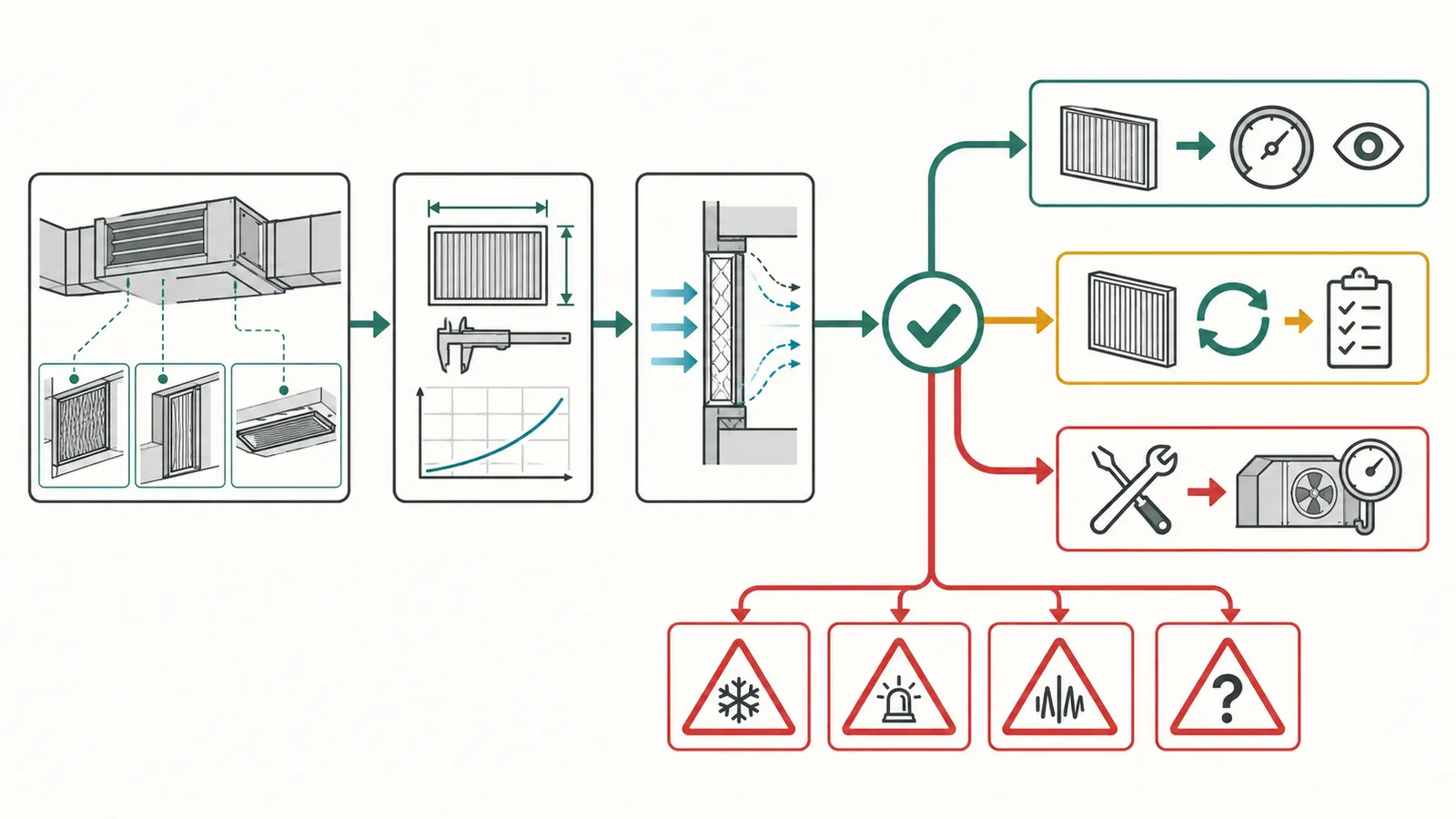
The next decision is one of three outcomes: install a verified candidate and monitor it, stay with the highest previously verified rating while collecting better data, or hand the complete record to an HVAC professional for airflow and equipment verification. The worksheet below is the original contribution for this guide. It turns EPA and manufacturer guidance into a recordable comparison without presenting a modeled result as a field measurement.
Filter compatibility worksheet: rating, resistance, fit and verification
Part A — State the decision before shopping
Write one sentence:
I am considering ____________________ because my household goal is ____________________. I will not use it unless ____________________ is confirmed.
Examples of a bounded goal include “reduce fine particles during seasonal smoke events” or “replace a discontinued filter while preserving the previously verified airflow.” Avoid writing “get the cleanest air possible” without naming the pollutant or operating constraint; that phrase pushes the decision toward a number without defining success.
Part B — Record prerequisites and exclusions
Check each item. “Unknown” is an acceptable result; it simply creates a handoff.
| Prerequisite | Entry | What counts as evidence |
|---|---|---|
| Existing system is ducted | yes / no / unknown | Return duct or grille leads to indoor air handler; model record |
| Ductless unit excluded | yes / no | No attempt to apply this worksheet to a mini-split head |
| Indoor-unit model located | model: __________ | Photograph or model-specific manual |
| All filter locations located | count: __________ | Walk-through and equipment inspection with system off |
| Current filter record complete | yes / no | Label, dimensions, depth, MERV and model |
| Candidate product identified | model: __________ | Package and data sheet, not a generic search result |
| Equipment limit located | yes / no | Manual value for airflow or pressure, with units and page |
| Local jurisdiction identified | city/county/state: ______ | Property location and AHJ contact, if alteration proposed |
| Professional handoff trigger reviewed | yes / no | Warning signs and unresolved limits understood |
Part C — Compare the exact filters
| Field | Current filter | Candidate A | Candidate B |
|---|---|---|---|
| Product/model | |||
| MERV claim | |||
| Nominal width × height × depth | |||
| Actual width × height × depth | |||
| Pressure drop | |||
| Pressure-drop units | |||
| Test airflow | |||
| Clean, loaded or final condition | |||
| Source URL and access date | |||
| Slot fit confirmed | |||
| Seal/gasket condition |
Use one candidate per column. Do not merge “MERV 13” from one product with pressure-drop data from another. If a manufacturer publishes multiple versions under one product family, record the exact model or package identifier. If no data is published, write “not published,” not an estimated value.
Part D — Calculate the screening comparison
Only complete this part when a model-specific maximum filter pressure drop and comparable candidate data exist.
Documented maximum filter pressure drop: __________ [same units]
Current filter pressure drop: __________ [same units]
Candidate A pressure drop: __________ [same units]
Candidate B pressure drop: __________ [same units]

Candidate A remaining allowance = maximum − candidate A = __________
Candidate B remaining allowance = maximum − candidate B = __________

Candidate A increment = candidate A − current = __________
Candidate B increment = candidate B − current = __________
Label the output “screening calculation.” Do not label it “measured airflow,” “approved filter,” or “safe system.” The calculation becomes a useful professional input when it preserves units, airflow test conditions and the document page. If the maximum is not clearly a filter limit, leave the calculation blank and request verification.
Part E — Inspect the physical installation
- Filter fits without bending, crushing or force.
- Actual dimensions match the rack requirement.
- Arrow direction matches the airflow direction in the manual or verified installation.
- Filter frame seats evenly.
- Access panel closes completely.
- Gasket is present, flexible and not visibly torn.
- No obvious daylight, loose edge or bypass path is visible.
- No second filter or accessory was added without documentation.
- Filter location is accessible without unsafe climbing or electrical exposure.
- A photograph of the installed filter and closed panel is saved.
An unchecked box is not automatically a failure of the whole HVAC system, but it is a reason not to claim that the higher MERV filter is working as intended. Correct the fit or ask for a professional repair before optimizing the rating.
Part F — Verify the operating result
Record observations after a normal cycle and again during the next monthly inspection:
| Observation | Before candidate | After candidate | Interpretation or follow-up |
|---|---|---|---|
| Blower or return sound | New whistle or strain needs review | ||
| Supply airflow at representative rooms | Observation only, not a measured pass | ||
| Comfort and cycle behavior | Compare similar weather and mode | ||
| Thermostat or equipment alarm | Stop and hand off if new | ||
| Indoor coil icing in cooling | Stop cooling and request service | ||
| Filter bowing or movement | Stop and inspect rack/pressure | ||
| Filter loading at one month | Set or adjust inspection interval | ||
| Moisture, odor or contamination | Stop comparison and investigate |
If a professional verifies airflow or static pressure, add the instrumented result, operating mode, filter model, date and the manufacturer's limit used for interpretation. If they recommend a different filter, record the reason: lower resistance, larger media area, corrected bypass, fan adjustment, rack repair, or another specific finding.
Method and limitations of this contribution
Method. Record the installed equipment and filter inputs, compare the exact candidate filter's published pressure-drop data at a stated airflow when available, inspect fit and bypass, then record airflow or static-pressure verification by the responsible HVAC professional when the manual does not establish compatibility. The worksheet was built by translating the inspected EPA ducted heat-pump guidance, EPA MERV explanation, EPA residential air-cleaner technical summary, EPA Indoor airPLUS filtration bulletin, ASHRAE residential airflow guidance, ENERGY STAR maintenance guidance, and the Carrier and Trane homeowner guidance into prerequisites, inputs, responsible parties, comparison fields, bounded formulas, verification steps and stop conditions. The evidence records for those claims are stored with this package and were accessed on September 8, 2026.
Limitations. This is an editorial decision aid, not a fan curve, engineering design, laboratory test, code document or warranty interpretation. A remote article cannot determine the installed system's minimum airflow, external static-pressure limit, controls, duct condition or local requirements. The illustrative pressure-drop numbers are modeled inputs only; they are not measurements and do not describe any brand or installed home. The worksheet cannot determine duct leakage, coil condition, blower control, filter loading rate or local rule from a remote article. A qualified HVAC professional must resolve those questions when the equipment documentation does not.
Compact originality brief
Current answers. Common answers give a calendar interval and often mention MERV 13 for indoor particles; manufacturer pages commonly describe dirty filters and airflow in broad terms.
Missing decision. They do not consistently show that the ducted forced-air system, return filter slot, exact filter construction and fan capability—not the heat-pump label alone—control compatibility. They also rarely give a homeowner a recordable path for comparing MERV benefit with resistance, bypass and verification risk.
Original contribution. The “Filter compatibility worksheet: rating, resistance, fit and verification” records the equipment prerequisite, exact product inputs, nominal and actual dimensions, MERV claim, comparable pressure-drop data, slot seal, household goal, installation date, observations, professional verification and stop conditions. Its modeled comparison shows formulas and sensitivity without inventing field measurements.
How to check it. A reader can reproduce the decision by opening the installed equipment manual, recording the candidate filter's own data sheet and test airflow, measuring the rack, inspecting the seal, repeating the observation log, and asking an HVAC professional to verify the unresolved airflow and pressure limits. The contribution is successful only if another person can see why the chosen filter was installed, what was measured or merely modeled, and what would trigger the next handoff.
The final decision should therefore be written plainly: “I will install [exact product] at [nominal and actual size], claimed [MERV], because [manual or professional evidence] supports it under [operating conditions]; I will inspect it on [date] and stop or call [responsible person] if [specific warning sign] appears.” If you cannot complete the bracketed evidence, keep the last verified filter and finish the record with the HVAC professional who can.
Cite this guide
Brictale. “What MERV Filter Is Safe for a Ducted Heat Pump Without Losing Airflow?.” Published 2026-09-24; updated 2026-09-24.
https://brictale.com/build/materials/choose-merv-filter-for-ducted-heat-pump-without-airflow-loss · Read the Markdown version
Original contribution: Filter compatibility worksheet: rating, resistance, fit and verification. A source-derived record that helps a homeowner compare replacement filters without treating MERV as a universal airflow guarantee.
Sources and scope
Evidence behind this page
- A ducted air-source heat pump does not by itself determine whether a home can use a high-efficiency filter; the forced-air system as a whole, including the fan and filter slot, must accommodate it.
Do ducted air source heat pumps filter fine particles out of indoor air?
US EPA guidance for ducted air-source heat pumps connected to conventional forced-air ductwork; it is not a model-specific approval.
Accessed · Link to this claim - MERV is a filter performance rating based on particle capture in specified size ranges, and EPA recommends MERV 13 or as high a rating as the system fan and filter slot can accommodate, with professional consultation sometimes needed.
US EPA explanation of MERV and national homeowner guidance; the recommendation is conditional on installed-system capability.
Accessed · Link to this claim - Higher-MERV filters tend to restrict airflow; deeper or wider media can provide more filtration area and lower resistance, but the fan, duct, filter width and total pressure drop must be considered together.
Indoor airPLUS Technical Bulletin: Filtration
EPA Indoor airPLUS technical bulletin for system design and installation guidance; it is not a universal retrofit permission or a local code rule.
Accessed · Link to this claim - Air bypass around a poorly matched or poorly sealed filter can substantially reduce filtration effectiveness, so installation instructions and a snug fit matter.
Residential Air Cleaners: A Technical Summary
US EPA technical summary covering residential fibrous-media and duct-mounted filters; observations apply to installation quality, not to a particular brand.
Accessed · Link to this claim - Filter resistance can increase as a fibrous filter loads with dust, and the initial and final operating resistance need to be accounted for when matching a filter and fan.
Residential Air Cleaners: A Technical Summary
US EPA technical summary discussing filter loading, airflow, resistance and residential system compatibility.
Accessed · Link to this claim - Airflow should be evaluated with a new filter and when the filter needs replacement or cleaning, using manufacturer literature for minimum acceptable airflow and maximum allowable static pressure.
ASHRAE Handbook: Residential Space Conditioning
ASHRAE handbook guidance for residential space-conditioning systems; the installed equipment literature remains the governing model-specific reference.
Accessed · Link to this claim - ENERGY STAR tells homeowners to inspect, clean or change filters monthly in central air conditioners, furnaces and heat pumps, while the exact replacement decision depends on condition and manufacturer guidance.
ENERGY STAR US homeowner maintenance checklist; monthly is an inspection/change instruction, not proof that every filter must be replaced monthly.
Accessed · Link to this claim - Ducted air-source heat pumps can connect to conventional forced-air ductwork, while ductless mini-splits do not use that ductwork.
ENERGY STAR product and homeowner guidance; used here to define the article's ducted scope and exclude ductless units.
Accessed · Link to this claim - Carrier's description of professional heat-pump service includes checking refrigerant and airflow, electrical safety, the blower assembly and the air filter.
Heat Pump Service & Maintenance Tips
Carrier US residential service guidance; task lists vary by contractor and equipment, so it is not a promise about every service visit.
Accessed · Link to this claim - Carrier advises homeowners to check filters monthly, explains that clogged filters restrict airflow, and identifies refrigerant, electrical and complex maintenance work as professional tasks.
Heat Pump Service & Maintenance Tips
Carrier US residential homeowner guidance; it supports maintenance and handoff boundaries, not a universal MERV rating.
Accessed · Link to this claim - Trane says homes and HVAC systems differ, gives a general 30-to-90-day filter-change range, and notes that thicker filters may last longer than 1-inch filters.
Trane residential maintenance guidance; the interval is general and must yield to the installed system's instructions and observed loading.
Accessed · Link to this claim - Trane's filter replacement steps call for turning off the air handler or furnace, inserting a correctly sized filter with the airflow arrow pointing toward the equipment, and turning the equipment back on.
Trane residential homeowner replacement procedure; the installed equipment manual controls where the disconnect and filter access are located.
Accessed · Link to this claim - Trane identifies common filter locations as return grilles, a filter box attached to the return duct, or a filter rack at the indoor equipment inlet.
Trane residential product guidance; actual location varies by installed system.
Accessed · Link to this claim - EPA Indoor airPLUS technical guidance calls for an appropriately sealed return-side filter slot and says the highest rated filter should be one the fan and slot can accommodate.
Indoor airPLUS Technical Bulletin: Filtration
EPA Indoor airPLUS construction and design guidance; it is not a national residential maintenance code or model-specific warranty approval.
Accessed · Link to this claim