How to Prepare a New-Home Maintenance Access Brief Before Design Development
Turn household maintenance tasks into a documented access, responsibility, replacement, and verification brief before your new-home design is frozen.
The short answer
Before design development, list each important maintenance, inspection, repair, and replacement task; name the person responsible; map the route and working clearance; record shutoffs and finish protection; and require the designer, builder, and trades to verify the matrix at design, rough-in, installation, and handover. Treat manufacturer clearances and the actual local AHJ requirements as project-specific, not assumptions.How to Prepare a New-Home Maintenance Access Brief Before Design Development
Before design development, make a task-by-task brief rather than a vague promise that the house will be “easy to maintain.” List routine maintenance, inspection, repair, and eventual replacement; assign a responsible person; map the route, working clearance, isolation point, and finish protection; then require the designer, builder, and trades to verify each row. Treat the actual local authority having jurisdiction (AHJ), manufacturer instructions, and site conditions as controlling.
This guide is for a United States single-family new build while the household brief and early design are still changeable. It does not provide permit-ready drawings, structural sizing, universal code requirements, accessibility certification, or permission for unsafe DIY work. A homeowner can define the decision and observe access; the architect or designer, builder, and qualified trades must resolve the technical design and local requirements.
The decision is simple to state but easy to lose in a drawing set: can the actual person who will own the house reach, isolate, service, inspect, and eventually replace each important component without an unreasonable route, unsafe improvisation, or unplanned demolition? The matrix below turns that question into a record that survives handoffs.
Start with the household decision, not a list of rooms #
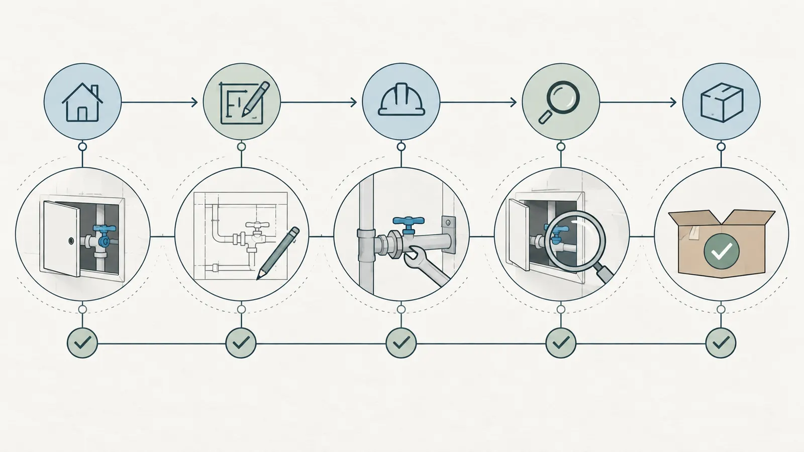
The right starting point is a household task inventory that says what must happen, who will do it, how often, under what conditions, and what evidence will prove the design supports it. A room list alone misses routes, shutoffs, access panels, lifting limits, seasonal work, and end-of-life replacement.
“Maintenance access” is not one decision. It is a bundle of decisions with different owners and consequences:
- A resident may replace a filter, clean an intake screen, reset a labeled control, inspect a visible leak, or read a meter.
- A resident may not be the right person to open energized electrical equipment, enter a confined crawlspace, climb an unprotected roof, disconnect fuel or refrigerant equipment, alter structure, or investigate combustion or gas hazards.
- A service technician may need a larger working position than a homeowner needs for a monthly task.
- A future replacement crew may need a route that is much larger than the panel used for normal servicing.
- A designer needs the requirements early enough to adjust room dimensions, ceilings, doors, chases, hatches, equipment locations, and finish transitions.
The first deliverable should therefore be a one-page decision statement at the top of the brief:
For each system or component that could affect health, safety, comfort, water control, energy use, or expensive finishes, the project team will document the routine task, assigned person, route, working position, model-specific clearance, isolation point, replacement path, finish protection, handoff record, and verification evidence before design development is frozen.
That statement is intentionally broader than “make the mechanical room accessible.” A mechanical room may be accessible while a filter door is blocked by a return duct, a shutoff is hidden behind a cabinet, or a replacement heat exchanger cannot pass through the door. The unit of planning is the task and its route, not the room label.
Set the scope boundary
Write the house assumptions before you inventory tasks. At minimum, record:
| Brief input | What to record | Why it changes the access decision |
|---|---|---|
| Jurisdiction | State, county, city or town, and the actual AHJ for building, mechanical, electrical, plumbing, fire, and any environmental review | A national guide cannot tell you which adopted code, amendment, permit, inspection, or local rule applies. |
| Project stage | Household brief, schematic design, design development, permit documents, construction, or handover | A route can still move during early design but may be expensive after framing, rough-in, or finishes. |
| Household | Number of occupants, ages, mobility or reach considerations, pets, allergies, work schedules, and likely future changes | The person responsible for a task determines whether “accessible” is meaningful. |
| Site and climate | Climate zone, humidity, wildfire or smoke exposure, snow or ice, dust, salt air, flood or storm exposure, and terrain | Outdoor intakes, filters, roof access, condensate, controls, and inspection frequency may change. |
| Systems concept | Heating, cooling, ventilation, water heating, electrical service, plumbing, envelope, storage, and specialty equipment | Each system creates different service, isolation, and replacement routes. |
| Participation | Whether the project seeks ENERGY STAR, Indoor airPLUS, utility incentives, or other voluntary verification | Program requirements can add documented design, access, testing, and verification tasks; they are not automatically local code. |
| Household capability | Tasks residents will do, tasks a caretaker will do, and tasks reserved for licensed or otherwise qualified professionals | Responsibility must be assigned rather than implied. |
The DOE Building America ventilation guide places code or program requirements, local ventilation, heating and cooling interactions, system selection, installation, and commissioning in the planning sequence. That is a useful model for this brief: first identify the inputs and constraints, then ask the designer and trades to turn them into a documented system and a testable handoff. DOE Building America’s whole-house ventilation planning guidance is not a substitute for the building department in the actual jurisdiction.
Do not infer that a family’s present habits will remain fixed. A filter that one healthy adult can reach from a step stool may become a poor requirement if the likely task owner is older, shorter, injured, or away for long periods. Conversely, specifying every task for homeowner performance can make the home less efficient or more expensive when a qualified technician is the safer and more economical owner. The goal is a deliberate assignment, not a promise that every person can perform every task.
Choose the important tasks
Do not attempt to predict every screw that might ever be removed. Include tasks that are frequent, safety-critical, likely to cause damage when missed, expensive to reach, dependent on another system, or likely to require finished-space disturbance. A practical first pass covers:
- Replace or clean HVAC and ventilation filters.
- Clean ventilation intake screens and access heat-exchange cores or condensate pans when the selected system requires it.
- Read and adjust normal controls, including a clearly labeled ventilation override where provided.
- Inspect condensate discharge, drains, pans, exterior terminations, and visible piping for blockage or leakage.
- Isolate domestic water, equipment water, fuel where applicable, and electrical power before qualified service.
- Inspect or service water heating, pumps, valves, expansion components, and relief discharge paths as required by the selected equipment and local practice.
- Inspect electrical service, distribution, disconnects, and equipment without treating energized work as homeowner maintenance.
- Inspect attic, roof, crawlspace, exterior cladding, penetrations, gutters, and drainage from a safe position or by a qualified person.
- Reach cleanouts, access panels, sensors, filters, batteries, lamps, control modules, and sacrificial components.
- Remove the largest likely replaceable component through a defined door, hatch, route, or exterior opening.
- Protect floors, walls, cabinets, roof membranes, landscaping, and finished equipment during service.
- Hand over manuals, labels, warranties, test results, as-built locations, shutoff maps, and maintenance instructions.
The list should include both ordinary work and failure response. A clogged filter or a sensor fault may be inconvenient; a leak above a finished ceiling or a failed valve behind fixed cabinetry can become a property-damage event. The brief should ask, “What is the safe first observation and isolation step?” before asking, “Who repairs it?”
Write each task as an observable outcome
Weak row: “HVAC accessible.”
Useful row: “The household can replace the specified filter at the labeled return location without moving furniture or using an unprotected ladder; the filter slides out in its intended direction; the access cover reseals; the filter size, rating, airflow limit, and replacement interval are recorded; the builder demonstrates the task before handover.”
The second row can be tested. It also exposes questions that otherwise remain hidden: Does the filter come out parallel to a wall? Does a condensate line block the cover? Is the proposed filter thickness compatible with the rack and pressure-drop limit? Is the replacement date based on the equipment designer’s instruction rather than a universal promise? The DOE filter guide specifically says filters should be easy for the homeowner to access, sized with airflow resistance in mind, and kept clear of wiring and condensate piping. Use the DOE filter installation guide for the filter-access and pressure-drop claims.
The next decision after this chapter is whether the task list is complete enough to take into a design coordination meeting. If the team cannot name the task owner or the first safe observation, it is not ready for the drawing.
Assign every task to a real person and a real sequence #
Every row should name a responsible person, the person who designs the provision, the person who installs it, and the person who verifies it. “The contractor” is too broad to be useful because an architect, general builder, HVAC trade, electrician, plumber, energy rater, commissioning provider, manufacturer representative, or AHJ may own different portions of the decision.
Use these responsibility fields:
| Role | Question the brief must answer | Typical evidence |
|---|---|---|
| Household task owner | Who notices, schedules, and performs the ordinary task? | A named household role, caretaker, or service agreement. |
| Designer or architect | Where is the component, route, working position, opening, barrier, and finish protection shown? | Coordinated plan, elevation, section, schedule, or detail. |
| Engineer or system designer | What performance, clearance, pressure, load, drainage, combustion, electrical, or structural requirements govern? | Calculation, equipment schedule, design report, manufacturer data, or sealed design where required. |
| Builder | Who coordinates trades, preserves the route, protects finishes, and records substitutions? | Coordination drawings, site photos, change log, and inspection record. |
| Specialist trade | What does the actual model require for service, isolation, removal, commissioning, and owner instruction? | Model-specific manual, installation record, startup sheet, test result, and demonstration. |
| Rater or verifier | Which voluntary program or third-party items are inspected or measured? | Completed checklist and test documentation. |
| AHJ | Which adopted code, local amendment, permit, inspection, or certificate applies? | Written jurisdictional answer, approved plan, inspection result, or permit condition. |
| Future service provider | Can the service company reach and remove the component with normal equipment and safe work practices? | Service review, proposed route, and model-specific access note. |
The person who performs the task is not always the person who bears responsibility for making the access possible. A resident can own filter replacement, while the HVAC designer owns the pressure-drop and filter-rack decision, the builder owns coordination around the rack, and the homeowner receives the correct size and instruction at handover. That is why a single “owner” column is not enough.
Sequence the work by decision dependency
Use this sequence so the brief reaches the people who can still change the design:
- Household discovery. Walk through a normal year. Record what you clean, inspect, reset, replace, call out, or avoid. Add likely future needs rather than guessing from a model home.
- Professional translation. Ask the architect or designer to identify the systems and spaces affected. Ask each system designer or trade for the actual maintenance tasks, clearances, isolation points, lifting or removal needs, and manufacturer documentation.
- Concept coordination. Place equipment, access panels, routes, doors, hatches, walkways, controls, shutoffs, and protected work zones on one coordinated plan. Resolve conflicts while walls and finishes are still movable.
- Design-development review. Run every matrix row through the four gates in the next chapter. Any “unknown” stays open; it does not become “pass.”
- Pre-rough-in confirmation. Confirm the selected or approved model, its access drawings, the route, the clear opening, service side, isolation, and replacement path. Substitution triggers a recheck.
- Rough-in verification. Before insulation or drywall hides work, photograph and measure routes, blocking, sleeves, shutoffs, cleanouts, drain paths, disconnects, and access openings. Compare to the matrix.
- Installation and commissioning. Verify that installed equipment, filters, controls, and terminations match the design. Ventilation systems should be commissioned and documented; the DOE guide says commissioning verifies that the installed system works as planned. DOE Building America explains new-home ventilation commissioning and design verification.
- Handover. The builder demonstrates the resident tasks, provides records and manuals, labels isolation points and controls, and records unresolved limitations with an owner and date.
- First-year feedback. Record actual problems, but do not silently revise the design record. Use the next service or warranty decision to decide whether a correction, instruction, or professional maintenance agreement is needed.
This sequence makes the handoff visible. It also shows why a final walk-through cannot repair a design that never had a replacement route. A finished access panel can be installed in the wrong room, in the wrong orientation, or too small for the actual component even when it looks tidy.
Separate normal resident work from hazardous work
Put a capability boundary in the brief. Homeowners may gather labels, measure a clear route, observe a visible drip, confirm that a control is labeled, replace a filter if the manufacturer allows it, and photograph the condition. They should not interpret these observations as proof that a system is safe to open or modify.
Assign the following to the appropriately qualified professional under the actual jurisdiction and equipment instructions: energized electrical inspection or alteration; gas, fuel, combustion, or refrigerant work; structural framing or roof changes; work in a confined or contaminated space; ladder or roof work with fall exposure; pressure-vessel or relief-device work; lifting heavy equipment; penetrations through fire-resistance or air barriers; and any permit-required work. A local license, permit, inspection, or training requirement may vary by state, county, city, or town. Name the actual AHJ rather than writing “code requires” without a jurisdiction.
The remote limit matters. A drawing, photograph, or video call can reveal an apparent blocked route, missing label, or wrong location. It cannot reliably prove structural capacity, electrical de-energization, combustion safety, concealed leakage, pressure integrity, fire-rating continuity, or compliance with the adopted local code. The safest next step for a suspected hazard is to stop, isolate only if the equipment instructions and qualified professional permit it, and call the responsible trade or AHJ.
Map the route, clearance, isolation, and replacement path together #
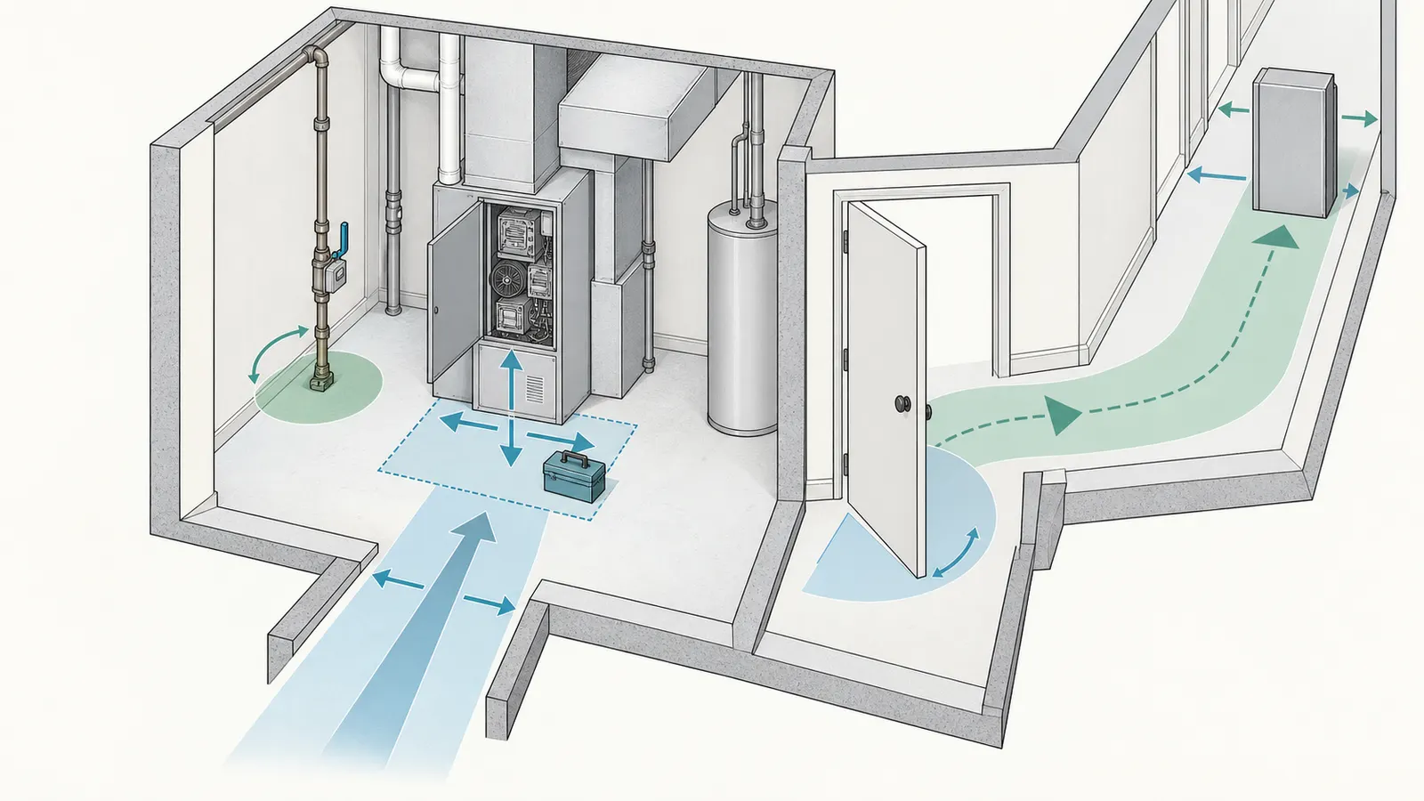
An access brief is complete only when it maps the person, object, tool, and waste path for the task, not merely the face of an access panel. For each row, show the approach route, body position, tool swing, component extraction direction, shutoff or disconnect, temporary protection, and future removal path on the coordinated design.
The WBDG Design Guide for Operational Excellence recommends early planning for unobstructed clearances, access to clearance spaces, inspections, maintenance capability, and spare parts. It also says maintenance, replacement, and removal should be planned early with doors, hatches, stairs, lifts, or hoists of adequate capacity and location. This is federal operational guidance, not a residential dimension table, but its design logic fits the homeowner decision. See the WBDG maintenance and replacement access guidance.
Record four different dimensions
Do not collapse all dimensions into a single “clearance” number. Record at least four:
- Approach clear width and height. Can the responsible person and normal tools reach the task without moving permanent objects? Measure the narrowest point, door leaf, hatch, stair, ladder, and turn.
- Working clearance. Can the person stand, kneel, reach, or position a tool while the access panel is open? Include the panel swing, drawer travel, removable cover, and adjacent hot, sharp, wet, or energized surfaces.
- Model service clearance. What does the selected manufacturer installation and service manual require around the actual model? Record the manual revision or page and whether the requirement is for airflow, combustion, access, removal, or code.
- Replacement envelope. What is the largest likely removable item, and what route allows it out? Record packaged and unpackaged dimensions, weight, orientation, lifting method, turning radius, floor protection, exterior weather conditions, and any temporary opening.
The model-specific field is deliberately blank until the equipment is selected. Do not fill it with a typical dimension from a different model. The final plan should show the selected model number, installation manual, service manual if separate, and the clearances that the designer and trade used. If the model changes, reopen the row.
The route should be tested in plan and section. A water heater may fit through a door while upright but need to be tilted or laid down at a stair turn. An air handler may fit through a rough opening but not with the service panel removed. A roof hatch may provide a person route but not the safe material-handling route for a replacement motor. The drawing needs the limiting condition, not the most flattering view.
Map isolation and verification points
Every component that might need service should have an explicit isolation answer:
- What is turned off or closed?
- Where is the isolation point relative to the component?
- Can the responsible person identify it without guessing?
- Is the point labeled and shown on the shutoff map?
- Does isolation create a secondary hazard, such as loss of heat, frozen pipes, loss of ventilation, flooding, or an alarm condition?
- Who verifies that the system is actually isolated before professional work begins?
- What test or observation proves the component can return to service?
For electrical equipment, “flip the breaker” is not a complete plan. The electrician must resolve disconnect location, circuit identification, lockout or safe work procedure, working space, and local requirements. For water, a main shutoff may stop the house but not a branch or appliance connection. For ventilation, an override control may be useful during adverse outdoor conditions, but it must be labeled and accessible to the occupant when the project uses the cited EPA program criteria. EPA Indoor airPLUS Version 2 identifies occupant-accessible ventilation overrides and documented ventilation verification.
Verification points should be observable and assigned. “Check HVAC” is weak. “HVAC trade records model, filter size, designed pressure-drop limit, access orientation, startup result, and owner demonstration; builder photographs the clear route before drywall” is reviewable. EPA’s program process likewise separates design coordination, construction verification, checklist records, and third-party inspection for participating homes. EPA’s Indoor airPLUS process describes design coordination and third-party verification.
Protect the finished house
Serviceability includes what gets damaged while the task is performed. Add a finish-protection field for:
- Floors on the route from exterior access to equipment.
- Wall corners, door frames, cabinets, counters, and stair treads.
- Roof coverings, membranes, flashing, and attic insulation.
- Finished ceilings below drains, valves, pans, and access panels.
- Landscaping, cladding, decks, and weather seals on an exterior replacement route.
- Paint, acoustic finishes, firestopping, air sealing, and moisture control around access openings.
The protection may be permanent, such as a service platform, curb, pan, walkway, wide door, removable panel, or durable floor surface; or procedural, such as a written requirement for a qualified trade to use protective coverings. If the only protection is “be careful,” the row is not complete.
The next decision is whether the proposed route remains valid after the project selects actual equipment and finishes. If the route cannot be drawn with the component’s largest service and removal envelope, stop design development for that row.
Use four go-or-no-go gates before design development is frozen #
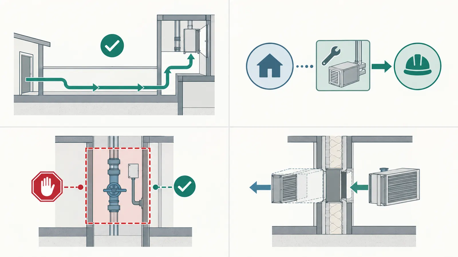
Before design development is frozen, every material row should pass four gates: reachability, responsibility, safe service, and replacement. A “not applicable” answer needs a reason. An “unknown” is a design action, not a pass.
Gate 1: Reachability
Pass only when the assigned person can reach the task through a defined route and use the component as intended without moving permanent obstructions or accepting an unplanned hazard.
Check the narrowest route, the access-panel orientation, the working position, tool reach, lighting, floor stability, temperature, moisture, and whether ordinary furniture or stored items will predictably block the task. A route through a storage room is not automatically usable if the equipment access requires emptying the room. A ceiling hatch is not automatically a route if a person must balance on joists or move insulation without a protected walkway.
For HVAC in an attic, DOE Building America gives an example of a pull-down or stair access and a permanently installed walkway to the furnace. If the equipment remains hard to access, the guide describes locating filters at accessible return grilles instead. Those are design strategies, not permission to skip the model’s service requirements or local code. DOE’s filter guide distinguishes accessible attic equipment from inaccessible equipment and locates filters accordingly.
The reachability test should be performed twice: once for the routine task owner and once for the qualified service provider. The resident may need a clear hand position; the technician may need a panel removed, test instrument, lighting, kneeling area, and safe carrying route. Passing the smaller task does not pass the larger one.
Gate 2: Responsibility
Pass only when a named person or service relationship owns the task, understands the boundary of their work, and receives the information needed to perform or request it.
Responsibility is not the same as legal authority. The household can own the reminder to replace a filter while the HVAC professional owns filter sizing and equipment compatibility. The builder can own delivery of manuals while the homeowner owns retaining them. The AHJ owns approval under its adopted rules, not the designer, rater, or Brictale.
For each task, write a sentence such as: “Resident checks the labeled filter monthly during the first season and replaces it only with the size and pressure-drop specification in the handover record; HVAC professional handles any rack modification or airflow complaint.” The sentence is stronger than “homeowner maintenance” because it defines the limit.
If no one wants the task, redesign the system, reduce the maintenance burden where reasonable, arrange a service contract, or accept the consequence explicitly. WBDG encourages designers to understand maintenance capabilities and to consider simpler approaches when available capability is limited. WBDG’s operational design guidance connects maintainability to the capabilities of the people who will operate and service the building.
Gate 3: Safe service
Pass only when the routine task and the professional service task have a defined safe work boundary, isolation method, clearance, lighting, and protection against the hazards actually present.
Do not use the matrix to authorize work. Use it to reveal when a qualified professional is needed. Relevant hazards include:
- Electrical: shock, arc flash, stored energy, wet locations, cramped working space, and mistaken circuit identification. Homeowner observations stop at labels and visible conditions; qualified electricians handle energized or de-energized equipment verification and modifications.
- Combustion, gas, and refrigerant: fire, explosion, carbon monoxide, pressure, hot surfaces, and refrigerant exposure. The homeowner should not disconnect, purge, charge, alter, or test these systems unless specifically authorized and qualified under applicable rules.
- Falls: roofs, ladders, attic access, stairs, platforms, and exterior equipment. A photo from the floor cannot validate a safe fall-protection system.
- Confined or contaminated spaces: crawlspaces, pits, tanks, attics with poor air quality, mold, pests, or insulation disturbance. Entry and remediation require an appropriate assessment and professional controls.
- Pressure and hot water: scalding, stored pressure, relief discharge, and unexpected flow. A shutoff location is useful, but opening a vessel or modifying a relief system is not ordinary homeowner service.
- Water and finish damage: hidden leaks, condensate overflow, drainage blockage, or freeze exposure can harm the house before a component fails visibly.
- Structural and fire barriers: cutting a joist, truss, wall, rated enclosure, roof, or air barrier to make access possible can create a new failure. The designer or engineer must resolve it.
Include “stop conditions” in the handoff: smell of gas or combustion products, damaged wiring, water near energized parts, unstable access, unknown insulation or contamination, unexpected pressure, structural movement, or a component that does not match the record. At a stop condition, the next action is to leave the unsafe work, prevent further damage if safe to do so, and contact the responsible qualified professional or emergency service as appropriate.
Gate 4: Replacement without unplanned demolition
Pass only when the largest likely replaceable item has a documented route and opening that do not depend on guessing, cutting finished construction, dismantling unrelated systems, or damaging less durable finishes.
A replacement path may be a wide exterior door, double-leaf door, stair, hatch, removable railing, equipment bay, garage route, or planned temporary opening. It may require a qualified lifting plan, floor protection, weather protection, and a structural review. The path should identify what must be removed and restored, who does it, and where the temporary work is recorded.
WBDG specifically warns that small openings can create significant replacement time and cost, and recommends planning the maintenance, replacement, and removal path early. It also says the means of replacement should not require imagining the dismantling or reconstruction of walls, floors, or roofs. Apply that principle to houses without turning it into a promise that every component can be replaced at low cost. WBDG’s equipment accessibility guidance covers maintenance, replacement, removal, doors, hatches, and adequate capacity.
The replacement gate is where attractive layouts often fail. A concealed air handler above a finished ceiling may be quiet and space-efficient but impossible to remove through the access panel. A tankless water heater in a narrow closet may be serviceable from the front but unable to pass through the door if the model or code-compliant replacement changes. A roof-mounted device may be replaceable only by lifting over a parapet, landscaping, or finished roof. Record the consequence while choices remain open.
Gate decision table
| Gate | Pass question | Evidence required before freeze | If it fails |
|---|---|---|---|
| Reachable | Can the assigned person reach and use the component through the planned route? | Dimensioned route, section, working position, access swing, lighting, and owner walkthrough. | Move component, enlarge opening, add permanent walkway/platform, relocate routine access, or reassign the task with an explicit service plan. |
| Assigned | Is one person or service relationship responsible, with a defined boundary? | Matrix role, written instruction, service contact or contract, and handoff owner. | Clarify ownership, simplify, procure service, or accept the risk deliberately. |
| Safely serviceable | Can the task be isolated and performed with the actual hazards controlled? | Isolation map, professional method, model instructions, local review where required, and stop conditions. | Stop design; obtain qualified review, add separation/protection/access, or change the system. |
| Replaceable | Can the largest likely item leave without unplanned demolition? | Removal envelope, route, opening, capacity, finish protection, and restoration plan. | Relocate, enlarge route, split equipment, add removable construction, or record the accepted future consequence. |
The next decision after the gates is not “approve the design.” It is “which failed or unknown row gets a responsible action, due date, and drawing revision before the design package advances?”
Build the whole-home serviceability matrix #
The matrix is the original contribution in this guide. It is an illustrative decision tool, not a field study or an official inspection form. Its purpose is to preserve the logic across household, design, construction, and handover decisions.
Matrix columns and how to fill them
Use one row for each task, not one row for each room. The minimum fields are:
| Column | Entry rule |
|---|---|
| System and component | Use a stable name and identify whether it is concept, selected model, or installed model. |
| Task and trigger | Write the action and what prompts it: calendar, visible condition, alarm, season, inspection, failure, or replacement age. |
| Frequency or life event | Use the manufacturer, designer, program, or household basis; write “verify” where no interval is yet known. |
| Responsible person | Name resident, caretaker, service provider, trade, designer, builder, rater, or AHJ. |
| Route | Describe where the person starts, the narrowest point, turn, door, hatch, stair, walkway, and destination. |
| Working position | State whether the person stands, kneels, reaches, lifts, uses a tool, removes a panel, or needs temporary equipment. |
| Model-specific clearance | Record manufacturer source, model, revision/page, and the governing clearance; never use a generic number as a substitute. |
| Isolation or shutoff | Name location, label, access, sequence, secondary effects, and qualified-person boundary. |
| Replacement path | Record largest item, dimensions, weight, orientation, lifting, opening, route, temporary protection, and restoration. |
| Finish protection | Record permanent platform/pan/walkway or service procedure for floors, walls, roof, landscaping, and barriers. |
| Handoff record | State the drawing, label, manual, schedule, test, photo, training, warranty, or contact to be delivered. |
| Verification evidence | State who checks it, when, how, and what counts as pass; include unresolved issue and due date. |
| Gate status | Mark pass, fail, or unknown for reachable, assigned, safe service, and replacement. |
For a homeowner brief, add two more columns that professionals often omit: what not to infer and next decision. “What not to infer” prevents a visible access panel from being mistaken for a complete service route. “Next decision” converts an observation into an action: select model, obtain manual, move equipment, confirm AHJ, add walkway, verify pressure drop, or schedule qualified review.
Illustrative matrix entries
The following entries are illustrative. They are not measurements from a real house and do not approve any design. Dimensions are shown only to demonstrate the record format; actual clearances and equipment requirements come from the selected model, applicable local rules, and the project’s qualified professionals.
| System / task | Responsible person and trigger | Route and access requirement | Isolation, replacement, protection, handoff | Verification and next decision |
|---|---|---|---|---|
| Ducted HVAC filter: inspect and replace when scheduled or visibly loaded | Resident; first-season check establishes the household schedule. HVAC designer specifies compatible size, rating, and pressure-drop limit. | From occupied floor to labeled filter slot or return grille; no furniture move or unsafe ladder for the resident task; access cover opens fully and wiring/condensate do not block it. DOE guidance supports homeowner-accessible filters and keeping wiring/piping clear. | Set thermostat/equipment as instructed; resident does not alter rack or airflow. Record size, depth, rating, airflow direction, recommended date, label, and spare storage. Protect floor from debris. | Resident demonstration, filter label, photo with cover open, HVAC trade startup record. If the slot is blocked or a high-resistance filter is desired, ask the HVAC designer to recheck pressure drop before selection. |
| Whole-house ventilation intake: inspect screen and clean debris | Resident observes intake; qualified trade handles fan or duct repair. Frequency depends on site exposure and instructions. | Exterior intake reachable without roof exposure or a safe professional route; screen can be removed and replaced without damaging cladding or weather seal. DOE recommends an accessible intake for maintenance and commissioning. | Isolate or override only as the manual permits; record contamination sources and the intake location. Protect seal, screen, and cladding. | Commissioning record and owner demonstration. If intake is near exhaust, dust, wildfire exposure, or inaccessible roof area, designer resolves location and controls with AHJ/program review. |
| ERV/HRV: filter and core/condensate service | Resident replaces filters if instructed; ventilation trade services core, pan, fan, and controls. | Access panel opens into a usable working position; service side has clearance from walls and stored items; condensate route remains visible and protected. EPA guidance identifies maintenance access and access to heat-exchange cores and pans where applicable. | Label filter, override, drain, and service disconnect as appropriate; record model manual, drain path, filter, and commissioning flow. Protect floor and ceiling below. | Trade records airflow and owner training; verify no access panel conflict. If the selected unit changes, reopen the clearance and condensate rows. |
| Main water isolation and equipment branch isolation | Household knows location; plumber designs and labels; qualified plumber performs alterations. Trigger is leak, service, winterization, or replacement. | Route from normal entry to labeled valve without moving fixed cabinetry or entering a hazardous space. Provide a visible map and an accessible drain/relief route where required by the design. | Close only as instructed; record what loses service and how to restore. Protect cabinet and finished floor from residual water. | Builder and plumber walk through with homeowner; photo, label, as-built map. If the only valve is hidden behind a removable panel, verify panel size, access, and replacement of the valve itself. |
| Water heater: service and eventual replacement | Qualified plumbing/HVAC professional; resident observes leak or alarm and calls. | Service side follows model manual; removal envelope reaches a door or planned opening without demolishing fixed finishes. | Record fuel/electrical isolation, water isolation, drain and relief discharge provisions, weight, route, pan or leak protection as designed. | Plumber records model, startup, relief/drain arrangement, labels, and handoff. If the route requires roof, wall, or cabinet demolition, redesign or record an explicit lifecycle consequence. |
| Electrical service/distribution equipment: qualified inspection or repair | Licensed or otherwise qualified electrical professional under the actual jurisdiction; resident reports heat, noise, odor, trip, or damage and does not open energized equipment. | Clear approach and working space per actual design and local requirements; service equipment and disconnect labels are visible. | Define disconnects, circuit directory, lockout/safe work procedure, and fire/wall penetrations. Do not infer de-energization from a label or switch position. | Electrician verifies location, labels, directory, and required inspection. If equipment is moved or service size changes, designer and AHJ re-review. |
| Attic/roof inspection | Homeowner observes from safe areas; qualified roofer or inspector performs roof or fall-exposed work. | Define whether inspection is from ground, attic walkway, hatch, scaffold, or professional access. Do not treat loose joists or stored boxes as a walkway. | Record lighting, walkway/platform, insulation protection, hatch, ladder, fall exposure, and weather limits. Protect ceiling finish and air barrier around hatch. | Designer/builder photo before concealment; qualified inspection at agreed interval. If a task requires roof entry the household will not safely perform, assign it to a service provider. |
| Controls and sensors | Resident uses labeled normal controls; trade diagnoses or replaces devices. | Controls are reachable, legible, not hidden behind furniture, and associated with the correct equipment. | Record override, reset, battery or hardwire, isolation, location, software/manual dependency, and replacement path. | Owner demonstration, label, model record, and functional test. If the control is only accessible through a service space, redesign or assign a professional service workflow. |
The matrix does not claim that every row applies to every home. It creates a visible decision surface. A row can be removed only when the design team states why the system or task is absent. A row can be marked not applicable when its trigger is impossible under the selected design, but “not selected yet” is not the same as “not applicable.”
Worked example: an illustrative filter-route test
Suppose an illustrative single-family design places an air handler in a closet. The resident’s filter task requires a front access door, a filter depth of 4 inches, a 25-inch filter extraction length, and a person standing in front of the rack. The draft plan shows a 30-inch nominal closet door, but the door casing, stop, and adjacent wall reduce the clear opening to 27 inches. The rack opens toward the hallway, and a finished cabinet is proposed 18 inches in front of the door.
Use these stated inputs:
- Required filter extraction length, (L_f = 25) in.
- Clear opening after trim, (W_o = 27) in.
- Minimum practical hand and cover clearance assumed for this illustrative test, (C_h = 2) in. on the extraction side.
- Cabinet projection into the working zone, (P_c = 18) in.
- Desired resident route width from the occupied floor, (W_r = 36) in.
- Actual route width after the cabinet, (W_a = 36 - 18 = 18) in.
The first check is the opening margin:
Opening margin = clear opening − extraction length
M_o = W_o − L_f = 27 in. − 25 in. = 2 in.
The 2-inch result is not a universal pass criterion. It is only the remaining geometric margin before considering the cover, hand position, model instructions, body position, filter flexibility, and whether the filter actually travels in the assumed direction. The actual HVAC designer and selected equipment manual control. The second check exposes a clear failure of the illustrative furniture arrangement:
Route margin = available route − desired route
M_r = W_a − W_r = 18 in. − 36 in. = −18 in.
The route fails because the cabinet occupies the task path. Possible design decisions are to move the cabinet, reverse the access orientation if permitted by the model, relocate the filter to a suitable return grille, enlarge the room, or reassign the task to a professional with a documented service route. The DOE filter guide describes return-grille placement as a strategy when equipment is difficult for a homeowner to access, but that does not eliminate the need to size and install the filter correctly. DOE describes accessible filter alternatives and filter sizing limits.
Sensitivity: what changes the result?
Change one input at a time and keep the others fixed:
| Scenario | (W_o) clear opening | (L_f) extraction | (P_c) cabinet projection | Route available | Interpretation |
|---|---|---|---|---|---|
| Base illustrative layout | 27 in. | 25 in. | 18 in. | 18 in. | Route fails; opening margin is only 2 in. before real service conditions. |
| Cabinet removed | 27 in. | 25 in. | 0 in. | 36 in. | Route problem is resolved, but model-specific working clearance still needs confirmation. |
| Wider door, cabinet remains | 34 in. | 25 in. | 18 in. | 18 in. | Opening improves; route still fails. A larger door does not solve a blocked approach. |
| Shorter filter | 27 in. | 20 in. | 18 in. | 18 in. | Extraction margin improves; route still fails, and a different filter may not be compatible. |
| Relocated return-grille filter | Not applicable at air handler | Model-specific | 0 in. at grille | Room route | Could make routine replacement easier; HVAC designer must check all return locations and pressure-drop effects. |
This illustrates why the brief uses separate route, clearance, and model fields. Fixing one dimension can leave another failure. It also shows why this is a planning calculation rather than a performance claim: no airflow, pressure, temperature, or field measurement has been made.
Worked example: deciding whether a replacement route is real
Consider a second illustrative case: a proposed air handler has an unpackaged width of 28 inches, height of 42 inches, depth of 24 inches, and weight of 190 pounds. The manufacturer’s removal instructions, exact clearances, lifting requirements, and whether the unit can be rotated are unknown at brief stage. The planned route has a 30-inch door, a 32-inch hallway, and a 90-degree turn into the mechanical closet.
Do not conclude that the unit fits because 28 inches is less than 30 inches. A replacement route needs at least:
- the actual clear opening after trim and hardware;
- the orientation in which the unit can pass;
- the turning geometry at the hallway and door;
- a safe lifting or dolly method for 190 pounds;
- floor loading and surface protection;
- clearance from stairs, railings, and finished walls;
- a place to stage the replacement without blocking egress or damaging the building;
- the manufacturer’s service and removal requirements; and
- a qualified person’s method for electrical, refrigerant, duct, drain, and structural disconnection.
The matrix should therefore mark the route unknown, not pass, until the selected model and trade review are complete. If a design decision must be made before model selection, reserve an envelope larger than the current concept and record the assumption. The next decision is either to select equipment that fits the reserved route or to revise the architecture. It is not to hope that a future installer will find a way.
Carry the brief through designer, builder, and trade handoffs #
The brief prevents access failures only when it travels with the design package and each handoff has an acceptance question. Attach the matrix to the project’s design decision register; give every row a stable identifier; and require changes to show which gate was rechecked.
Homeowner to designer
Give the designer:
- the household task inventory and likely task owners;
- mobility, reach, sensory, schedule, pet, allergy, and future-use considerations that affect who can perform work;
- preferred locations for visible controls, filters, shutoffs, meters, and storage;
- unacceptable routes, such as roof access, unstable crawlspace entry, or moving furniture;
- tolerance for service visits, temporary loss of a system, noise, and finish disturbance;
- the systems and tasks that must be homeowner-manageable versus professional-only;
- climate and site exposures, including humidity, snow, dust, smoke, salt, flooding, and terrain; and
- the replacement and finish-protection priorities, not just the initial layout preference.
Ask the designer to return a coordinated plan and section with equipment, access openings, routes, service zones, shutoffs, controls, walkways, hatches, doors, and likely replacement envelopes. If a provision is intentionally omitted, ask where the task goes instead. A beautiful plan that leaves an access task unassigned is incomplete.
The WBDG access guidance treats equal access as a life-cycle consideration spanning planning, design, construction, operations, maintenance, and training. It is written for the built environment broadly and is not a certification for the private home, but it reinforces the timing of the homeowner’s request: access belongs in planning, not only in the final walk-through. WBDG places access across the building life cycle.
Designer to builder
The designer’s handoff should identify the requirement behind each space, not merely show an equipment symbol. For each access-sensitive row, provide:
- the plan and section reference;
- required opening and working zone;
- model assumption and substitution rule;
- route and removal envelope;
- shutoff, disconnect, drain, control, and label locations;
- finish-protection requirement;
- pre-cover inspection point;
- commissioning or functional test;
- owner demonstration; and
- unresolved decision, responsible party, and due date.
The builder should ask the trades to coordinate against the same matrix. The builder is not expected to invent equipment clearances, but should not allow framing, ductwork, piping, electrical work, insulation, drywall, cabinets, or finishes to consume the documented access zone. WBDG recommends access provisions that minimize maintenance task duration and calls out doors, hatches, stairs, lifts, and hoists of satisfactory capacity and location. WBDG’s early-design guidance supports coordinated access provisions and capacity.
At pre-rough-in, compare the proposed installation with the latest model and matrix. At rough-in, photograph what will disappear. At pre-drywall, remeasure clear openings and routes. At finish, check that trim, cabinets, flooring, insulation, firestopping, and covers preserve the requirement. Substitutions are not administrative details; they can change dimensions, weight, panel direction, drainage, control location, and replacement path.
Builder to specialist trade
Give the trade the matrix row and ask for a written response in five parts:
- Model and task list: What model is being installed, and what routine, service, and replacement tasks does the manufacturer identify?
- Clearance and route: What service and removal clearances are required, measured from what surfaces, in what orientation, and through which opening?
- Isolation and hazards: Where are the disconnects, shutoffs, drain or relief routes, and safe work boundaries?
- Commissioning and records: What will be measured, adjusted, labeled, photographed, and placed in the handover packet?
- Owner instruction: What may the resident do, what must a professional do, what should trigger a call, and where are the manuals and replacement details?
For ventilation, the DOE guide says installation and commissioning should verify that the system works as planned. EPA Indoor airPLUS Version 2 includes documented ventilation measurement, accessible filters, and labeled occupant override controls within its program requirements. These claims apply within their cited guidance and program scope; the trade still needs to follow the selected manufacturer, adopted local requirements, and the actual project contract. Compare DOE commissioning guidance with EPA’s verification requirements and EPA’s Version 2 verification text.
Handoff record format
Use a stable ID such as M-07-HVAC-FILTER or A-03-ATTIC-ROUTE. Every revision should preserve the ID and show:
| Handoff moment | Required record | Owner of the record |
|---|---|---|
| Household brief | Task, trigger, responsible person, boundary, priority, and unacceptable failure | Homeowner |
| Concept or schematic design | Location, route, access concept, working zone, control and shutoff concept | Designer and system designer |
| Design development | Selected model or reserved envelope, manual source, clearance, replacement path, finish protection, gate status | Designer, builder, trade |
| Pre-rough-in | Current model, coordinated drawings, substitution review, AHJ or program questions | Builder and trades |
| Rough-in/pre-cover | Measurements, labels, photos, blocking, sleeves, shutoffs, drains, disconnects, and route preservation | Builder and trade |
| Installation/commissioning | Installed model, startup, functional tests, ventilation flow or other applicable measurements, unresolved limits | Specialist trade, rater/verifier where applicable |
| Handover | Manuals, labels, maps, maintenance schedule, contacts, warranties, demonstration, as-builts | Builder and homeowner |
| First service | Actual issue, root cause, correction, and whether design record needs an update | Homeowner and service provider |
Do not use a generic “owner’s manual provided” checkbox as proof of a handoff. The record should tell the household which page or label answers the next question. If the builder cannot demonstrate the filter, isolation, control, or access path, mark the row incomplete and name the next action.
Verify at the right stage and close failure branches #
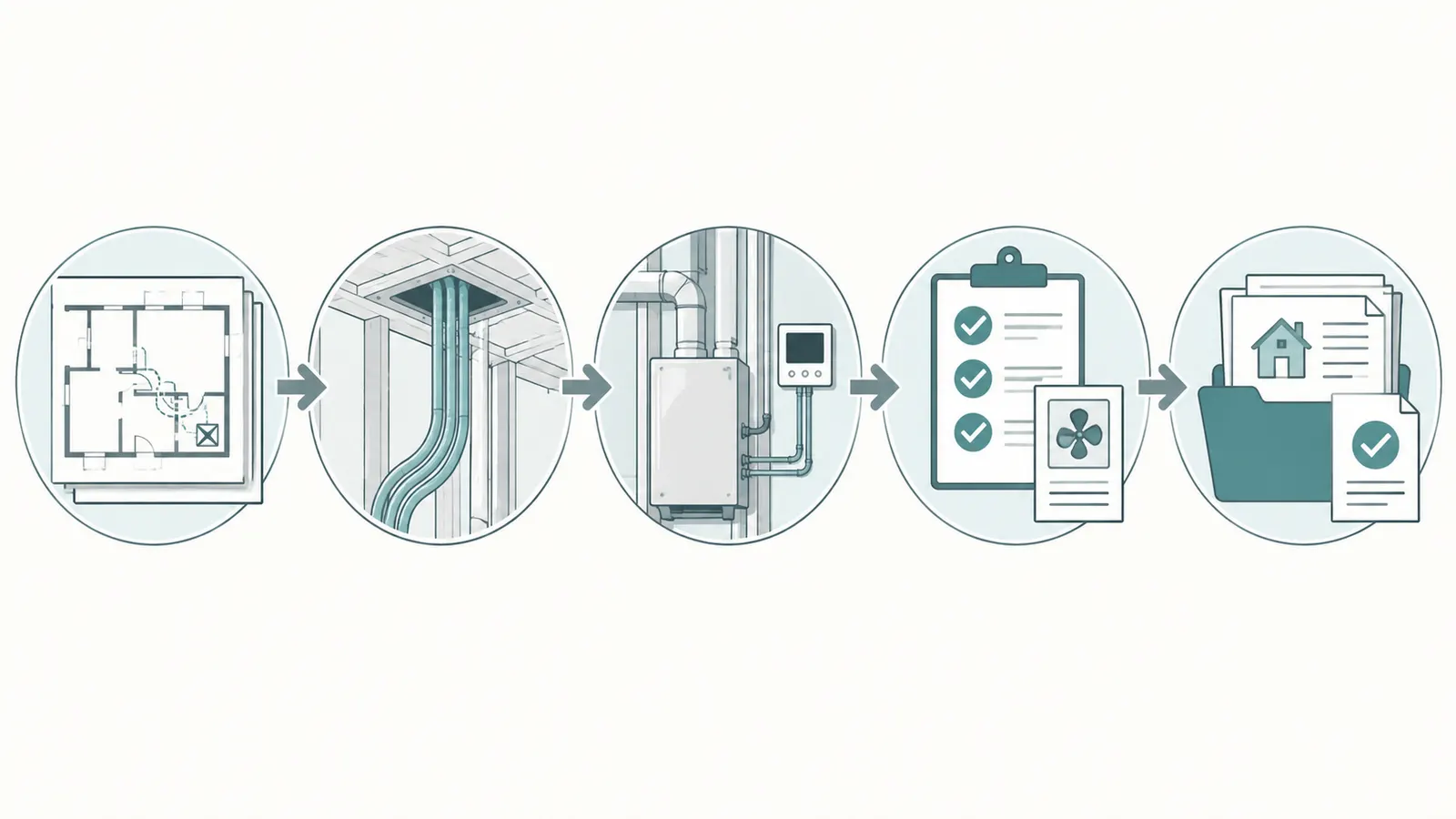
Verification should be staged because different facts are visible at different times. A final inspection cannot see a blocked route behind a finished wall, and a drawing review cannot prove that a trade installed the model with the intended orientation.
Stage 1: brief and concept review
At the household-brief stage, verify completeness rather than dimensions:
- Are all major systems and foreseeable tasks listed?
- Is every task assigned to a person or service relationship?
- Are hazardous tasks separated from homeowner tasks?
- Are climate, occupancy, schedule, capability, and future-use inputs recorded?
- Are local AHJ questions identified by actual jurisdiction?
- Is every important failure connected to a safe first action and next decision?
If a system has not been selected, create a reserved service envelope and mark model-specific clearance unknown. If the proposed layout depends on an assumption about a future model, make the assumption visible.
Stage 2: design-development review
At design development, verify the four gates with plans and sections. Ask the designer and system trades to draw:
- the person approach route;
- access-panel swing and extraction direction;
- required service clearance;
- the replacement envelope;
- the shutoff or disconnect route;
- drain, relief, condensate, or discharge paths;
- working lighting and floor protection;
- adjacent finishes and barriers that may be damaged;
- labels and owner controls; and
- the evidence expected at rough-in, commissioning, and handover.
Do a conflict review across disciplines. HVAC access can conflict with electrical working space; a plumbing cleanout can be hidden by a cabinet; a ventilation intake can conflict with an exhaust termination or contamination source; an attic walkway can conflict with ducts, insulation, and roof trusses; a replacement route can conflict with a structural wall or rated assembly. The point is not to make every conflict disappear by decree. It is to assign the professional who resolves each one.
Stage 3: rough-in and pre-cover review
Before insulation, drywall, cabinets, or ceilings conceal work, verify the installed locations and dimensions. Take photos with a visible scale and room reference, but do not rely on photos alone. Record:
- clear opening and route measurements;
- access-panel position and swing;
- equipment support, blocking, platform, or walkway;
- shutoff, disconnect, drain, and cleanout labels;
- sleeves, penetrations, seals, insulation, and firestopping;
- condensate and relief discharge routes;
- filter rack, filter direction, and cover seal;
- outdoor intake and exhaust locations;
- access to service sides and removal route; and
- deviations from the coordinated drawing.
For ducted HVAC filtration, DOE guidance says the filter cover should seal against leakage and that wiring and condensate piping should not block access. EPA’s Version 2 guidance similarly calls for pressure-drop-aware filter design and gasketed or comparably sealed access panels in the cited program scope. DOE gives filter access, sealing, and obstruction checks; EPA gives pressure-drop and filter-panel sealing guidance.
This stage is also the right time to identify a silent failure: the drawing may show an access panel, but the rough-in may place a pipe, conduit, duct, or framing member behind it. An empty rectangle on a plan is not evidence of usable access.
Stage 4: installation, commissioning, and finish review
After equipment is installed, verify the actual model and the actual task. The installer should open panels, remove filters or serviceable components as the manual permits, access drains or cores, operate controls, and demonstrate the route. The homeowner can observe and ask questions; hazardous service remains the professional’s responsibility.
For ventilation systems, record the commissioning method, measured result, controls, filter, intake, exhaust, and owner instructions. DOE says a new-home whole-house ventilation system should be commissioned after installation so it works as planned; its guidance also notes that climate and humidity affect system choices. DOE’s ventilation guide covers commissioning and climate-related humidity considerations. Do not turn that into a national claim that one ventilation system or one commissioning test fits every U.S. house.
At finish review, test the interaction with real finishes and normal storage. Open the panel with the floor covering installed. Move a representative piece of furniture into the room. Check that labels remain visible, that a cover can be removed without damaging paint, and that the route is not silently narrowed by trim, casing, handrails, or cabinets. If the resident’s task requires an object to be moved, decide whether that is acceptable and record it; do not let the assumption remain unwritten.
Common failure matrix
| Failure observed | What it may mean | What not to infer | Safest next action | Bring to the professional |
|---|---|---|---|---|
| Filter cover opens only partway | Duct, pipe, cabinet, or wall blocks the intended task | Do not infer that a smaller filter, force, or tape will solve it | Stop routine service and ask HVAC designer/trade to review rack, route, and pressure drop | Model, rack dimensions, photos, filter specification, drawing, and obstruction measurement |
| Access panel exists but no standing or kneeling space | Access is cosmetic rather than usable | Do not infer that a technician can “work around it” safely | Recheck working clearance and consider relocating equipment or enlarging access | Section, service manual, body/tool position, and finish conflict |
| Equipment fits the room but not the door or turn | Replacement path is unproven | Do not infer that the future unit can be disassembled without consequences | Ask trade for removal envelope and lifting/route plan before finishes | Model, dimensions, weight, door clear opening, turn, stairs, and protection plan |
| Shutoff is behind fixed cabinetry or insulation | Isolation may be delayed during a leak or service call | Do not infer that the main shutoff is equivalent | Have plumber/designer map branch isolation and accessible panel | Valve location, affected fixtures, panel dimensions, leak scenario |
| Intake or exhaust is inaccessible or near contamination | Maintenance or indoor-air performance may be compromised | Do not infer that a screen or longer duct fixes location | Ask designer and HVAC trade to recheck location, distance, access, and local requirements | Site plan, elevations, terminations, exposure, and program choice |
| Resident cannot identify a control or label | The system may be operable only by a professional | Do not infer that an app or hidden breaker is an adequate handoff | Label and demonstrate normal operation, override, reset, and call-for-service boundary | Manual, control schedule, label photo, and owner questions |
| Access route crosses a roof, crawlspace, ladder, or confined area | Routine inspection may have fall, contamination, or entry hazards | Do not infer that occasional access is safe | Assign task to qualified service provider or design a safe route | Hazard assessment, route, frequency, and service agreement |
| Installed model differs from matrix | Clearances, controls, weight, and replacement path may all change | Do not infer that a similar model is interchangeable | Reopen the row and obtain current manual and trade confirmation | Approved substitution, model numbers, drawing revision, and gate status |
| Finished access damages paint, flooring, insulation, or air barrier | Service cost includes restoration or may discourage maintenance | Do not infer that “careful work” is a permanent protection | Add durable protection, revise opening, or define restoration responsibility | Photos, finish schedule, panel, route, and protection proposal |
The failure matrix is an escalation tool, not a remote diagnosis. A homeowner can document what is observable. The professional decides whether the cause is a design, installation, equipment, code, safety, or maintenance problem.
What verification can and cannot establish
A successful walkthrough establishes that the demonstrated task was possible under the demonstrated conditions. It does not prove future performance, code compliance in every jurisdiction, equipment life, energy savings, indoor-air quality, water tightness, or safe work under all weather and failure conditions. Those conclusions require the relevant design professional, trade, testing method, program verifier, or AHJ.
Likewise, a voluntary program checklist is not a local permit. EPA describes Indoor airPLUS as a process with builder and verifier roles, design coordination, checklists, and third-party inspection for participating homes. Use that evidence to organize documentation when the project chooses the program; do not represent it as approval by the city, county, state, or other AHJ. EPA explains the scope and roles of its Indoor airPLUS process.
The next decision is closure: for every failed or unknown row, does the project change the design, select different equipment, add a protection or access provision, assign a professional service path, confirm the AHJ, or explicitly accept a future cost and risk? An unresolved row with no owner is not a closed row.
Finish with a usable handover and next decision #
The final maintenance access brief should become part of the home’s ownership record, not disappear into the design process. At handover, the homeowner should receive a concise system map plus the evidence that makes the matrix actionable.
Handover checklist
Ask the builder and trades to demonstrate or deliver:
- A room-by-room equipment and access map.
- Manufacturer model and serial records, manuals, installation instructions, and service contacts.
- Filter locations, sizes, depths, ratings, airflow direction, pressure-drop or design limits where specified, and replacement instructions.
- Ventilation intake, exhaust, filters, controls, override, commissioning results, and cleaning instructions where applicable.
- Main and branch shutoff locations, equipment disconnects, control labels, drain and relief paths, and a clear statement of what the homeowner must not open or alter.
- Access panels, hatches, walkways, platforms, ladders, doors, and finish-protection requirements.
- Photos and measurements of concealed routes, blocking, sleeves, firestopping, air sealing, insulation, and pre-cover conditions where relevant.
- Startup, functional, airflow, pressure, leak, or other applicable test records.
- Warranty boundaries and the contact for a failure, leak, alarm, comfort issue, or suspected hazard.
- A first-season review date, especially for filter loading, humidity, condensate, drainage, controls, and route conflicts that only appear in use.
- An unresolved-items list with owner, due date, temporary measure, and acceptance evidence.
Have the resident perform only the tasks that are within the agreed boundary. A good demonstration may show how to locate a shutoff without asking the resident to open a panel, how to replace a filter without modifying a rack, how to use a labeled ventilation control, and how to recognize a condition that needs a professional. If the task requires a ladder, roof entry, electrical opening, combustion work, pressure work, confined-space entry, structural change, or unknown contamination, the handover should say so plainly.
Set the first-year feedback loop
The first year tests the brief’s assumptions, not the homeowner’s competence. Keep a short log with date, task, condition, person called, time to access, obstruction, damage, and resolution. Record whether the issue arose from:
- an incomplete household inventory;
- an incorrect responsibility assignment;
- a model substitution;
- a blocked route or reduced clearance;
- a missing label or manual;
- an unsafe or impossible service boundary;
- an unplanned replacement or restoration problem; or
- a performance or commissioning issue unrelated to physical access.
Do not claim that this log is a controlled study or measured product performance. It is an owner record that helps decide whether a correction, warranty request, service arrangement, or future design change is appropriate. If the same access failure affects a health, safety, water, electrical, structural, or fire-protection condition, escalate promptly to the qualified professional and actual AHJ where applicable.
Make the next decision explicit
At the end of the brief, write one of these next decisions for each major system:
- Proceed: all four gates pass, the model and local requirements are documented, and the verification owner is assigned.
- Revise design: the route, working clearance, isolation, finish protection, or replacement path fails.
- Select and recheck equipment: the system concept is acceptable but the actual model is not yet known.
- Obtain professional or AHJ review: the issue involves code, structure, electrical, combustion, pressure, falls, contamination, or a local approval question.
- Assign service responsibility: the household will not perform the task; a qualified service relationship and route are documented.
- Accept a bounded lifecycle consequence: the owner deliberately accepts a future cost or temporary opening, with the consequence and trigger recorded rather than hidden.
“Proceed” should be rare at the household-brief stage when the actual model, local review, and installation are still open. It means the decision logic is complete enough to advance, not that construction has been approved.
Originality brief and limits of the contribution
Current answers: Existing search answers are fragmented. Homeowner checklists tend to describe finished-home chores. HVAC guidance explains filter locations or replacement. Federal and institutional maintainability guidance discusses early planning and equipment access. Program documents explain verification. These sources rarely preserve a homeowner’s cross-system decision from daily task through design, builder coordination, trade installation, replacement, and handover.
Missing decision: Before design development, the homeowner needs to decide which person can safely perform or request each task, what route and clearance that task requires, what isolation point and finish protection it needs, and what the team must verify before the design becomes expensive to change.
Original contribution: The Whole-home serviceability matrix and four-gate review combines a task-level record with four explicit gates: reachable, assigned, safely serviceable, and replaceable without unplanned demolition. The matrix’s inputs are the household, site and climate, system concept, selected model, responsible person, route, clearance, isolation, replacement envelope, finish protection, handoff record, and verification evidence.
Method: For each task, record the responsible person, frequency, route, required working clearance, model-specific clearance source, isolation point, replacement path, finish protection, handoff record, and verification evidence. Apply four go/no-go gates: reachable, assigned, safely serviceable, and replaceable without unplanned demolition. The illustrative worked example uses stated dimensions and formulas, not collected field data.
The illustrative filter example shows units and formulas for opening and route margins and tests sensitivity when a cabinet, door, filter length, or filter location changes.
How to check it: A homeowner can inspect whether every major task has all required fields, whether each failure has an owner and next decision, and whether the designer and trades can demonstrate the route. The project team can compare the matrix to coordinated drawings, model manuals, rough-in photographs, commissioning records, labels, and handover documents. The contribution should be rejected or revised when it invents a clearance, treats a program rule as national code, assumes a substitution is equivalent, or marks a route as passed without testing the actual working and replacement envelope.
Limitations: This is a planning synthesis, not a code document, engineering calculation, accessibility certification, manufacturer approval, inspection report, or evidence of field performance. Final dimensions, electrical and mechanical details, fire separations, structural changes, permit requirements, and safe work methods must be confirmed for the actual house, jurisdiction, equipment, and qualified professionals.
This limitation means the guide uses federal and program guidance to organize a homeowner decision; it does not create a local rule. Final structural capacity, electrical and mechanical details, fire and air-barrier continuity, permits, licenses, safe work procedures, and equipment compatibility belong to the actual architect, engineers, builder, qualified trades, program verifier where chosen, and AHJ for the house’s location.
For related planning decisions, continue through Brictale’s design and layout path, then connect the matrix to materials and systems, construction coordination, and handover and ownership. The immediate next action is to schedule one design-development meeting with the matrix open and refuse to close a row that still says “unknown.”
Cite this guide
Brictale. “How to Prepare a New-Home Maintenance Access Brief Before Design Development.” Published 2026-09-13; updated 2026-09-13.
https://brictale.com/build/design/prepare-new-home-maintenance-access-brief · Read the Markdown version
Original contribution: Whole-home serviceability matrix and four-gate review. A reusable way to convert household maintenance, inspection, repair, and replacement tasks into explicit access, responsibility, isolation, route, finish-protection, handoff, and verification requirements before design development.
Sources and scope
Evidence behind this page
- The DOE Building America Solution Center says new-home whole-house ventilation planning should determine residence ventilation rates, identify applicable code or program requirements, assess local and whole-house ventilation together, assess heating/cooling and ductwork interactions, select a system, and install and commission it.
Whole-House Ventilation Strategies for New Homes
U.S.-oriented DOE Building America guidance for planning and commissioning whole-house ventilation in new homes; not a jurisdiction-specific code determination.
Accessed · Link to this claim - DOE Building America guidance says outdoor-air intakes should be located where maintenance, airflow verification, and commissioning can occur, and recommends an accessible intake grille for maintenance cleaning.
Whole-House Ventilation Strategies for New Homes
DOE Building America guidance for outdoor-air intake siting and maintenance in new-home ventilation systems.
Accessed · Link to this claim - DOE Building America guidance says ducted HVAC filters should be accessible to the homeowner, filter sizing must account for airflow resistance and system pressure drop, and wiring or condensate piping should not block filter access.
Proper Installation of Furnace and Air-Handler Filters
DOE Building America filter installation guidance for ducted heating and cooling systems; exact filter selection remains dependent on the designed equipment and applicable requirements.
Accessed · Link to this claim - DOE Building America guidance recommends a permanently installed walkway and stair or pull-down stair access where an attic furnace must be reached, and recommends return-grille filters when the equipment location itself is difficult for the homeowner to access.
Proper Installation of Furnace and Air-Handler Filters
DOE Building America examples for homeowner and service-technician access to attic or inaccessible HVAC equipment; not a universal stair, walkway, or building-code specification.
Accessed · Link to this claim - EPA Indoor airPLUS Version 2 verification requirements call for a clearly labeled ventilation override accessible to occupants, verified outdoor-air inlets, measured and documented ventilation, and outdoor-air filters accessible for maintenance.
Indoor AirPlus Verification Requirements Version 2
EPA Indoor airPLUS Version 2 program requirements for homes and multifamily buildings; program verification criteria, not a blanket U.S. building-code rule.
Accessed · Link to this claim - EPA Indoor airPLUS Version 2 guidance says ventilation equipment should be accessible for cleaning and maintenance and, where applicable, access to heat-exchange cores and condensate pans should be provided.
Indoor AirPlus Verification Requirements Version 2
EPA program advisory and verification language for ventilation equipment; applies when the project elects the referenced Indoor airPLUS requirements and does not replace manufacturer instructions.
Accessed · Link to this claim - EPA Indoor airPLUS Version 2 says a project’s outdoor-air filter design should account for pressure drop and that filter access panels should use gasket material or a comparable sealing mechanism to prevent air bypass.
Indoor AirPlus Verification Requirements Version 2
EPA Indoor airPLUS Version 2 requirements and advisories for ducted heating, air-conditioning, and ventilation filtration; not a substitute for the equipment designer’s pressure-drop limits.
Accessed · Link to this claim - EPA says builders and verifiers should coordinate during design and planning to review the overall design, moisture management, mechanical specifications, and other program requirements, and that a third-party verifier inspects the home against the applicable checklist before the label is earned.
How to Build, Verify and Report Indoor AirPlus Labeled Homes
EPA’s Indoor airPLUS program process; applies to participating labeled homes and does not make a voluntary program inspection equivalent to the local AHJ inspection.
Accessed · Link to this claim - WBDG’s federal Design Guide for Operational Excellence says early design should provide unobstructed clearances, access to clearance spaces, convenient spare parts, and provisions for inspections, while accounting for maintenance staff capability.
Design Guide for Operational Excellence
Federal Whole Building Design Guide guidance for operational and maintainability decisions in building programming and design; residential application here is a bounded planning synthesis, not a residential code rule.
Accessed · Link to this claim - WBDG says designers should plan equipment maintenance, replacement, and removal access early; provide doors, hatches, stairs, lifts, or hoists of adequate capacity and location; and avoid replacement paths that require imagining dismantling or reconstructing walls, floors, or roofs.
Design Guide for Operational Excellence
Federal WBDG maintainability guidance for equipment access and end-of-useful-life replacement; exact dimensions and structural or life-safety provisions require the actual design team, manufacturer, and AHJ.
Accessed · Link to this claim - WBDG describes equal access as a life-cycle consideration spanning planning, programming, design, construction, and operations and maintenance, including staff training.
Provide Equal Access and Flexibility
WBDG accessibility and life-cycle design guidance; it does not certify a private home or establish the applicable accessibility law for a particular U.S. jurisdiction.
Accessed · Link to this claim