How to Map Seasonal Solar Obstructions Before Siting a New Home
Map trees, terrain and buildings against seasonal sun positions before schematic design so your architect can compare house locations with traceable site evidence.
The short answer
Before schematic design, document the lot’s city, state, county, climate zone, latitude, longitude and true-north basis. For each candidate house pad, record every meaningful tree, building, ridge and future obstruction with bearing, distance, height difference, date, time and confidence. Use a location-specific sun-position source for seasonal checks, then ask the architect to model the best candidates. This record is a planning aid, not a survey or legal solar-rights opinion.How to Map Seasonal Solar Obstructions Before Siting a New Home
Before schematic design, record the lot’s city, state, county, climate zone, coordinates and true-north basis. Map trees, terrain, neighboring buildings and likely future obstructions from each candidate pad, then compare their estimated elevation angles with location-specific sun azimuth and elevation at representative seasons and occupancy times. Give the dated register to the architect. It can show when another pad or orientation deserves testing, but it cannot replace a survey, prove a solar right or guarantee indoor comfort.
Decide what “enough solar access” means for this house #
Enough solar access is not a universal number of sunny hours; it is documented evidence that a candidate house location can support the household’s stated daylight, glare, passive-heat and outdoor-comfort priorities after the architect considers windows, rooms, shading and climate. The first decision is therefore not “Is this lot sunny?” It is “Which candidate pad and orientation gives the design team a credible chance of meeting the brief, and what unresolved obstruction could change that choice?”
Sunlight is a site input, not a finished design. A clear view to the south may help a living room with winter daylight, yet increase summer heat or glare if the window, overhang, glass and room use are wrong. A large tree may reduce afternoon overheating, preserve an outdoor sitting area and still be a problem if it blocks a bedroom’s desired winter light. A neighboring house may cast a narrow shadow on the lot now, while a permitted addition or mature tree could change the future view. The record must preserve these competing effects instead of turning “sunny” into an unsupported suitability label.
The U.S. Department of Energy’s passive-solar guide describes the basic seasonal relationship: passive design uses the sun’s lower winter rays for warming and higher summer rays for deflection, while orientation, elevation, room layout, materials and surroundings all contribute. That is a design relationship, not a promise about a particular property. DOE’s Guide to Passive Solar Home Design also gives a commonly cited passive-solar rule that windows face within 30 degrees of true south and are not shaded during a winter 9 a.m. to 3 p.m. period. Treat that as a design reference to discuss with the architect, not as a national code rule or a threshold that makes a lot “approved.”
Building America makes the same point in a more site-responsive way: natural-comfort orientation considers the house shape, climate, sun exposure and shading, and window and overhang placement must control solar exposure. PNNL’s Proper Solar Orientation guidance is educational material funded by the U.S. Department of Energy, not a formal training, certification or site approval. Your job before schematic design is to make the site conditions visible enough that a qualified design team can test them.
For related planning decisions, browse Brictale’s homeowner blog after this guide; the blog is the site’s single homeowner feed, while this article remains focused on the solar-obstruction handoff before schematic design.
The decision boundary
Use the register to sort each candidate into one of three working outcomes:
| Working outcome | What the record shows | Next decision |
|---|---|---|
| Proceed to schematic testing | The candidate has a consistent north basis, known or bounded obstructions, and no high-impact seasonal conflict with the household brief | Ask the architect to model this pad and one backup before fixing the massing and glazing plan |
| Compare alternatives | One or more obstruction angles are close to the relevant sun elevations, or the candidate trades winter light for summer comfort | Have the architect model at least two pad/orientation options with the same room and window brief |
| Stop and resolve a prerequisite | The pad, north reference, lot constraints, obstruction height, future condition or jurisdiction is too uncertain | Obtain the missing survey, site information or local-rule answer before treating solar access as a design input |
“Proceed” does not mean “build here.” It means the solar question is sufficiently documented to earn professional modeling. “Stop” does not mean “the lot fails.” It means the uncertainty is large enough that a remote homeowner observation should not drive a durable siting decision.
Originality brief
Current answers generally explain that a long east-west axis, south-facing glazing, overhangs and trees influence daylight and solar heat. The missing decision is how a homeowner turns a real lot’s trees, buildings, terrain and possible future obstructions into a dated comparison that an architect can inspect before schematic design.
The original contribution is the Seasonal solar-obstruction register and siting worksheet. It adds a row-level record for the source of each input, true-north convention, candidate pad point, obstruction bearing, horizontal distance, height difference, observation date and time, seasonal sun-position check, confidence label and architect handoff. It is a planning worksheet, not a new solar-geometry standard.
Method: record the lot latitude and longitude, true-north convention, candidate pad point, obstruction bearing, horizontal distance, height difference, observation date and time, then compare the obstruction elevation angle with location-specific NOAA sun azimuth and elevation checks for representative seasons.
Limitations: this worksheet is not a boundary survey, tree survey, topographic survey, permit-ready site plan, energy model, structural analysis, arborist opinion, or legal solar-access determination; an architect and appropriate local professionals must verify project decisions.
You can check the contribution by asking whether another person can reproduce each row from the attached source, site photo, map, measurement or professional document; recompute the angle; identify the season and time represented; and understand what decision is still owned by the architect, surveyor, civil professional, arborist, or local authority. If a row cannot be checked, label it unknown instead of filling the gap with confidence.
State the priorities before collecting sun data
Write a short household brief before you measure. It can be provisional, but it should name the rooms and times that matter. “We want passive solar” is too broad to compare candidate pads. A usable brief might say:
- The main living space should receive useful winter daylight without depending on direct sun every day.
- The kitchen should avoid severe late-afternoon glare during the household’s occupied hours.
- A home office needs a stable view and controllable screen glare.
- A south-facing outdoor area is desirable, but summer shade matters more than winter heat gain.
- Bedrooms may prioritize privacy and low dawn glare over solar collection.
- The project will use mechanical heating and cooling; passive gains are a comfort and load consideration, not the sole heating plan.
These priorities prevent an error that looks technical but is actually editorial: measuring every obstruction with equal importance. A two-degree obstruction over a living-room window during a desired winter hour can matter more than a taller obstruction on a façade with no planned glazing. Conversely, a clear south view may be irrelevant if the lot’s best floor plan puts the living room elsewhere because of access, slope, septic setbacks, wildfire defensible space, flood constraints or a local height limit.
Name the actual place and climate context
Use the physical lot’s city, state and county, not the nearest major city used by a generic sun-path graphic. Record the parcel or project address, latitude and longitude in decimal degrees, time zone, and whether daylight-saving time was active for each observation. The city and state identify the jurisdiction to contact; the coordinates identify the solar calculation point; the county and climate-region lookup provide a first design context.
DOE Building America describes climate regions using heating degree days, average temperature and precipitation and offers county-oriented guidance. DOE’s climate-zone page is useful for framing the design conversation, but it does not determine every applicable code requirement. The project architect must verify the actual code edition, adopted energy path, local amendments and authority having jurisdiction for the city or county where the home will be built. If the parcel sits in an unincorporated area, name the county and the responsible county department rather than writing “local code.”
Record a climate label as a source-linked input, not as an assumption. Building America climate regions and the code’s IECC climate zones may not use identical names or boundaries. A coastal city, mountain parcel and inland valley can have different practical comfort issues even when a general map places them in a broad family. The register should have separate fields for “Building America climate region, if used,” “applicable energy-code climate zone, to verify,” and “design team interpretation.” Do not use the worksheet to infer insulation, window SHGC, HVAC sizing or overhang dimensions.
Assign responsibility before the visit
The homeowner can assemble observations and a traceable first-pass register. The architect or designer should decide which candidate pads and orientations deserve modeling, translate the observation into room and window implications, and coordinate a survey or energy model when precision matters. A surveyor establishes boundary, elevation and site-control information; a civil professional addresses grading and site constraints; an arborist evaluates tree identity, health, mature size and risk; and the local planning or building authority answers jurisdiction-specific rules. No remote record can transfer those professional responsibilities to the homeowner.
Make the handoff explicit:
| Question | Homeowner can prepare | Professional verification or decision |
|---|---|---|
| Where is true north? | Copy the north arrow and source from a survey, plat, GIS map or other named document; label a phone compass as approximate | Architect and survey professional reconcile the drawing basis with the project survey |
| What blocks the horizon? | Photograph and list trees, buildings, ridges, poles and visible structures from candidate pad points | Surveyor, architect, civil professional or arborist verifies geometry, elevation, ownership and future condition as needed |
| What matters indoors? | State room, view, glare, daylight and comfort priorities and occupied times | Architect places rooms, windows, shading and massing and coordinates performance analysis |
| What is allowed? | Ask the city, county, HOA or other identified authority the exact question and save the answer | Architect or land-use professional interprets the jurisdiction’s written rule for the proposal |
| Is the comparison enough? | Mark confidence and unresolved questions | Architect decides whether another pad, orientation, survey or model is required |
This division also prevents a common handoff failure: the architect receives attractive site photos but not the time, direction, height, distance, source and uncertainty behind them. A photo can show a tree; it cannot by itself show whether the tree blocks the sun at 9:15 a.m. on a winter date from a particular future window.
Establish a true-north site basis before measuring anything #
Use one named, stable north reference for the register, and distinguish true north from magnetic north and grid north before recording bearings. A bearing that is off by 8 degrees can move a low winter sun path onto or away from a tree canopy in the worksheet, especially when the obstruction and sun are near the edge of an opening. The best basis is the north arrow and coordinate reference on a current project survey or reliable site plan; a homeowner compass is a temporary field check, not the controlling document.
Understand the three norths
True north is geographic or geodetic north. Magnetic north is where a magnetic compass points at the location and time. Grid north is the direction of the map grid, which can differ from true north because a curved earth is represented on a plane. USGS explains the three north arrows and notes that magnetic declination varies with position and time. USGS’s north-arrow explanation is a useful primer when a plat, map or phone app uses different conventions.
NOAA NCEI defines magnetic declination as the angle between magnetic north and true north and explains that it changes with location and time. NOAA NCEI’s magnetic-bearing conversion guidance documents the convention for converting an approximate compass observation. In a register, write the convention rather than just writing “north.” Examples are:
- “True north from boundary survey dated 2026-04-18; architect to confirm survey basis.”
- “Map north from county GIS; approximate location and grid basis not confirmed.”
- “Magnetic compass bearing, 2026-09-08, declination source and correction recorded; field observation only.”
Use the documented sign convention: declination (D) is positive when east of true north and negative when west, and true bearing (T) equals magnetic bearing (M) plus declination, (T = M + D). NOAA NCEI’s bearing-help page states this addition rule and the west-negative convention. Normalize the result to the 0–360° range: if (T) is 360° or more, subtract 360° until it is below 360°; if it is negative, add 360° until it is at least 0°. Thus an illustrative 170° magnetic bearing with 7° east declination becomes 177° true; 358° magnetic plus 7° becomes 365°, which wraps to 5° true. Record the raw magnetic reading, signed declination, model or source, date and formula so the architect can audit it. If you cannot verify the declination or north basis, label the bearing magnetic and request reconciliation rather than presenting it as true.
Build the minimum site base map
Start with a copy of the most reliable site document you possess. It may be a boundary survey, topographic survey, recorded plat, civil concept, or a parcel map used only for orientation. Mark its source, issue date, scale, coordinate reference if shown, north type, vertical datum if shown, and what it does not establish. If you have no survey, a parcel map can help organize an observation but cannot establish a buildable pad, setback, easement, grade or boundary.
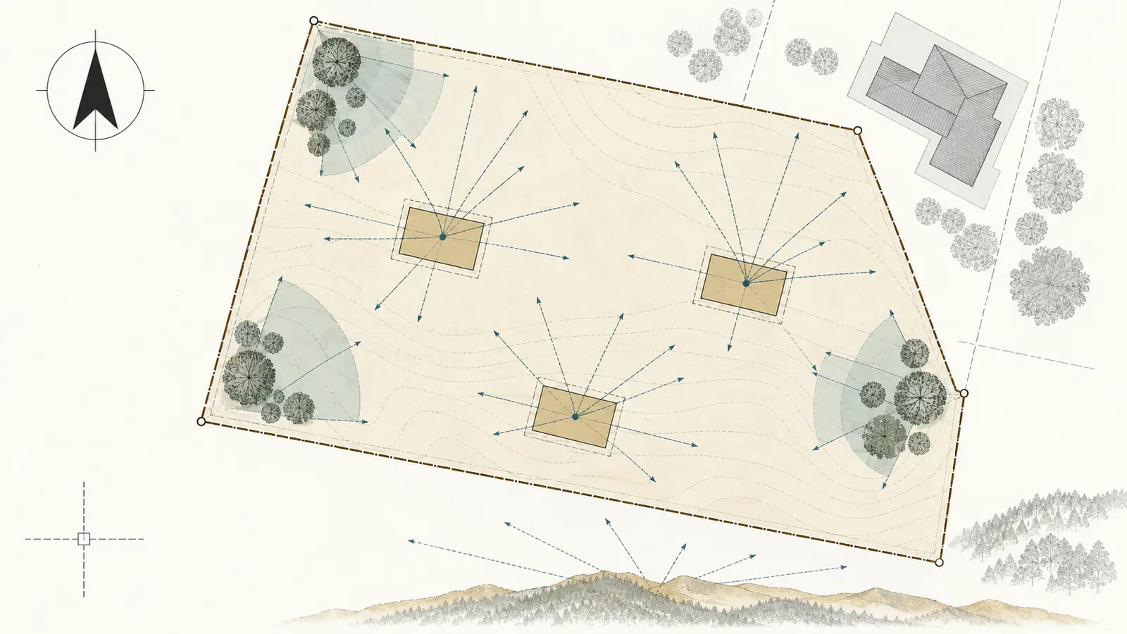
Add the candidate house pad as a point or a small rectangle, not as a final footprint. Name alternatives A, B and C. For each alternative, record the center point or a consistent reference corner, the assumed finished-floor elevation if known, and why the point is being considered. Keep the pad geometry provisional because moving the house 20 feet can change a nearby tree’s obstruction angle and can also change access, grading and utilities.
Draw rays from each candidate pad to major obstruction sectors. A sector is more useful than a single dot when the future façade or window wall is not designed. Use practical bearings such as N, NNE or 22.5-degree sectors for the first pass, then use finer angles when a candidate is close to a decision boundary. Record whether the obstruction is:
- A fixed object: existing building, retaining wall, rock face, ridge or utility structure.
- A living object: tree, hedge, shrub or vegetation whose height, canopy and deciduous state change.
- A moving or temporary object: construction equipment, parked vehicles, seasonal storage or temporary shade cloth.
- A future or legal uncertainty: likely new building, allowed addition, planned tree, zoning envelope, easement or an unresolved HOA or local rule.
The category affects confidence. A survey point on a stable building corner may be high confidence for position. The height of a neighboring tree estimated from a photograph is not high confidence merely because the photograph is sharp.
Keep observation conditions with the record
Every observation row should include date, local clock time, time zone, daylight-saving status, weather or visibility note, observer, device or method, and whether the photo direction was checked. A cloud-free day is not required to measure a tree’s physical location, but it matters if you are using shadows or a visible sun position as a corroborating observation. For this worksheet, a photograph taken through a windshield, made with a wide-angle lens, or taken from an unknown camera height is a bounded workflow limitation: it may not preserve the scale, viewpoint or reference needed for a reliable comparison. Use that image to identify a follow-up question, not to derive a bearing or angle; retain the original file and mark the row low confidence until a safer, better-referenced observation or professional measurement is available.
Save the original photo, not only a cropped screenshot. Use a filename that identifies the candidate and bearing, such as pad-A-225-SW-tree-2026-09-08-1615-local.jpg. If a map or online source is used, save its name, URL, access date and visible coordinates. Do not treat an aerial image as current ground truth: construction, leaf cover, tree height and imagery date can all differ from the visit.
Avoid unsafe field collection
Stay on land where you have permission and observe from stable ground. Do not climb trees, roofs, retaining walls or vehicles to improve an angle. Do not enter a neighboring property, active construction site, roadway or fenced area to obtain a better photograph. Do not cut branches, move obstructions, probe unstable slopes or approach damaged trees. If the site has steep terrain, ice, wildfire damage, flood debris, aggressive animals, overhead conductors or active construction, stop and ask the responsible professional or property owner how the observation should be collected.
The moderate safety boundary here is about falls, unstable ground, traffic, overhead electrical hazards and misrepresenting site information, not about operating household water equipment. A homeowner can make a visual register from safe observation points. Surveying, climbing, tree work, electrical clearance evaluation, excavation, grading and structural or retaining-wall assessment belong to qualified professionals.
Build the obstruction register from candidate pad points #
Record each obstruction as geometry plus uncertainty, not as a vague note such as “trees to west.” A useful row lets another person answer five questions: where was the candidate pad, what direction is the obstruction, how far away is it, how high is it relative to the observation point, and when or under what assumptions was the information collected? Add the design implication only after the raw observation is preserved.
Use a row structure that survives the handoff
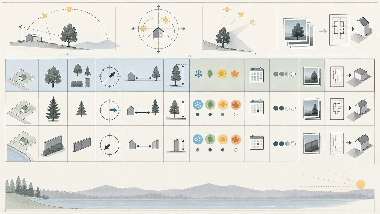
Create one row per obstruction or obstruction group. The following fields are enough for a first-pass register:
| Field | What to enter | Why it matters |
|---|---|---|
| Candidate pad | A, B or C; reference point or corner | A sun path has meaning only from a defined location |
| Obstruction ID | T-01, B-02, Ridge-01, Future-01 | Lets photos, maps and questions stay connected |
| Type and condition | Deciduous tree, evergreen tree, building, ridge, future envelope | Condition changes by season or by future action |
| Bearing | Degrees clockwise from true north, or raw magnetic value with correction note | Aligns the object with solar azimuth |
| Distance | Horizontal distance in feet or meters; source and approximate accuracy | Converts height into an angular obstruction |
| Height difference | Top of object above observation point, in feet or meters | Ground-to-top height alone can misstate the angle on a slope |
| Width or sector | Approximate angular width or left/right edge bearings | A canopy or building blocks a range, not a mathematical point |
| Observation | Date, local time, weather, camera or measuring method | Makes the row auditable |
| Seasonal behavior | Leaf-on, leaf-off, evergreen, construction or growth assumption | Determines whether one season can be inferred from another |
| Confidence | High, medium, low with reason | Stops approximate inputs becoming false precision |
| Source file or link | Photo, survey sheet, map, authority email or field note | Preserves evidence and retrieval path |
| Architect handoff | Model, verify, ask authority, obtain survey or accept tradeoff | Turns observation into a next action |
Keep raw and derived fields separate. “Distance: 80 ft, tape estimate” is raw. “Obstruction elevation: 6.7 degrees” is derived. “Winter south-window risk: medium” is an interpretation. If the distance changes after a survey, you should be able to update the formula without rewriting the observation.
Measure bearings from the same reference point
Stand at the candidate pad reference point and aim toward the obstruction’s near edge, center and far edge. If the pad is not accessible, state the substitute observation point and the offset between it and the intended pad. For a building, record the corners that define the relevant façade. For a ridge, record several points along the skyline rather than treating the highest point as the whole obstruction. For a tree, record trunk location, canopy edge and approximate crown top if visible.
If a future façade will be 50 feet long, a single bearing from the pad center may miss the fact that the north end has a clear view while the south end faces a tree. Early in planning, record sectors. Later, the architect can project the actual window openings and calculate which parts of the obstruction matter to which room.
When using a phone compass, remove magnetic objects and step away from vehicles, metal fences, utility equipment and reinforced concrete where practical. Calibrate only according to the device’s instructions, record that it was a magnetic reading, and do not mix phone bearings with a survey’s true bearings without a conversion note. The intent is traceability, not a claim of survey accuracy.
Estimate distance and height without hiding uncertainty
For a first pass, horizontal distance can come from a tape, laser distance meter, scaled plan, map measurement or a clearly labeled estimate. On a slope, the straight-line distance visible in a photograph is not necessarily horizontal distance. If the difference could affect the siting decision, ask for a topographic survey or professional site model.
Height should be the top of the obstruction relative to the candidate observation point, not automatically the tree’s or building’s total height above its own ground. A building on higher terrain may have a large height difference even when its wall is not tall. A tree crown above a lower neighboring grade may be less obstructing than a shorter tree on a bank closer to the pad. If you know only total height, record it as a lower-confidence proxy and explain why.
Useful homeowner methods include a professional survey or elevation data supplied by the project team, a measured distance plus a clinometer reading, a two-point field method on stable ground, or a scaled photograph with a known reference. Do not climb or stand beneath unstable objects to improve the result. When the risk or uncertainty is material, the safest next step is a professional measurement, not a more elaborate phone trick.
Record vegetation as a time-dependent obstruction
A tree is not one obstruction. Its trunk, branches, leaf-on canopy, leaf-off branch structure, mature size, health, species, irrigation, exposure and possible removal or replacement all affect the design question. Note whether it is deciduous or evergreen if known, but do not infer species from a distant photograph when the distinction could change the result. Ask an arborist when tree health, mature size, hazard, root protection or removal is part of the actual decision.
PNNL’s shading guidance describes useful but conditional landscape patterns: deciduous trees south of a home can block summer sun while allowing winter solar heat gain, and large trees set away from a home can block lower-angle east or west sun while preserving some views and breezes. PNNL’s landscape-shading section supports the seasonal logic, not a recommendation to plant, remove or retain a specific tree. Local tree-protection rules, wildfire requirements, utility clearance, ownership, easements, nuisance law and HOA conditions are jurisdiction- and property-specific and are outside this worksheet.
Use separate rows for leaf-on and leaf-off assumptions if the canopy is a key obstruction. A statement such as “T-01 blocks 30 degrees in summer” is incomplete unless it says where the 30 degrees came from, at what height, at what pad point, and whether it means a solid leaf-on screen or the branches’ physical outline. If the intended room needs daylight rather than direct sun, the architect may also care about diffuse light through a canopy; do not collapse that into a binary blocked/unblocked field.
Include terrain and buildings beyond the lot line
The horizon can be blocked by a neighboring house, apartment, garage, retaining wall, hill, ridge, forest edge or elevated road. Map these even when they are outside the parcel. You are recording a solar obstruction, not deciding that you have a right to alter it. Do not label a neighboring property as a future obstruction because it might someday be redeveloped; instead, label the present object and create a separate “future condition to verify” row if a written plan, zoning envelope or design scenario makes it relevant.
For a neighboring building, record its apparent top edge and the document or observation supporting its location. If a local regulation could cap height or allow an addition, identify the actual jurisdiction and department to contact, write the question precisely, and save the written answer. Examples are “What height envelope applies to the lot at [address]?” or “Does the city require a tree permit for removal of a protected species at this parcel?” Do not write “the code allows” unless the responsible jurisdiction, code edition, section or written response has been verified.
For terrain, a contour map or topographic survey is more useful than an online hill-shading layer for a final decision. This worksheet treats a digital elevation model as a screening input only: its resolution, coverage, processing and vertical reference may not match the project question, so a small bank, ridge detail or elevation basis can remain unresolved. That is a bounded Brictale workflow limitation, not a claim that every model has those defects. Record the model or map source, date, resolution if stated and vertical datum if stated, then send it to the architect or civil professional with its unresolved questions.
Convert each obstruction into an auditable angle #
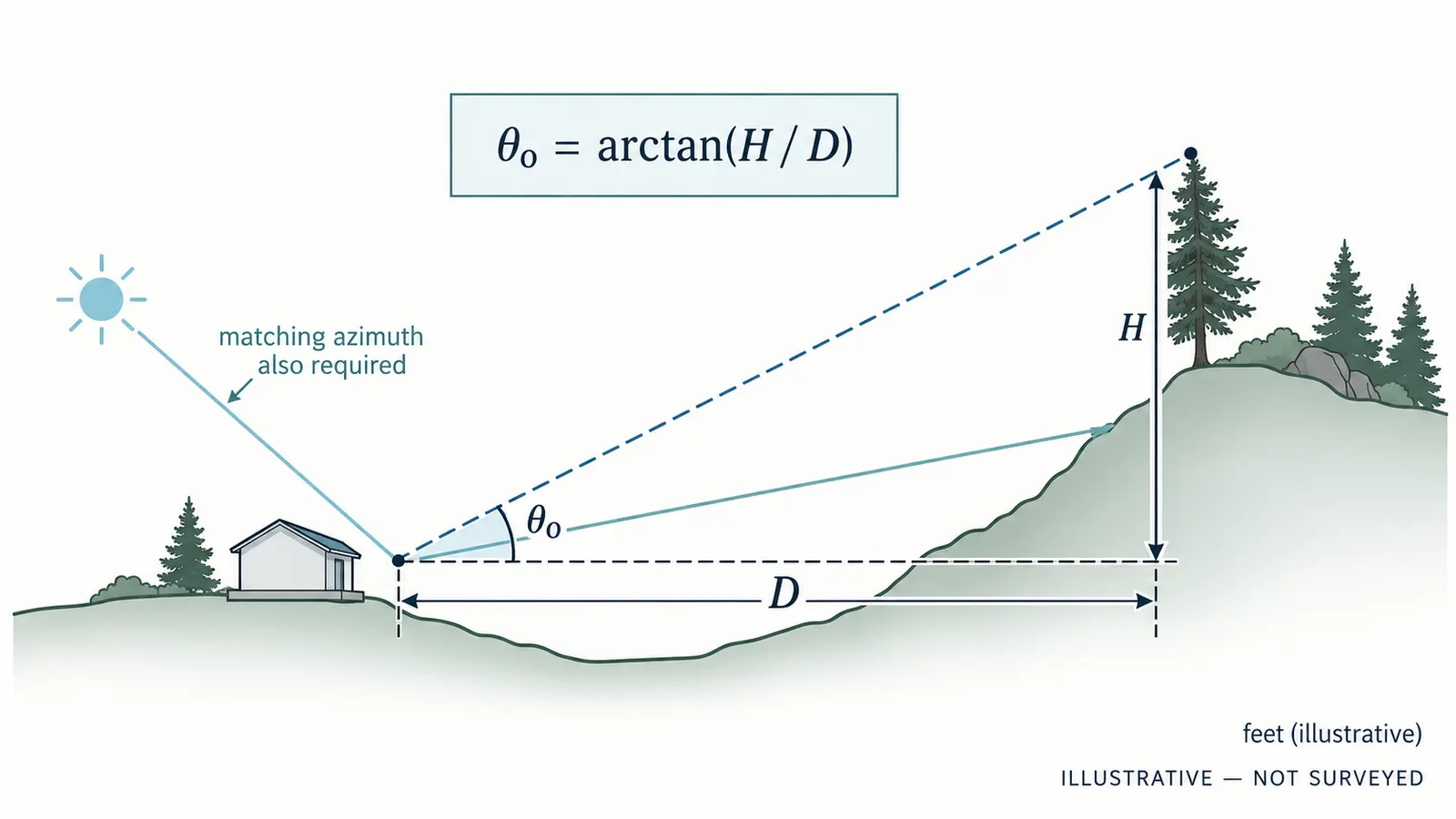
Compare an obstruction’s elevation and azimuth with the sun’s elevation and azimuth from the same candidate pad and north basis. The core first-pass calculation is simple: obstruction elevation angle equals arctangent of height difference divided by horizontal distance, converted from radians to degrees. The comparison is meaningful only when the units, bearings, observation point and assumptions are consistent.
Use the basic geometry
Let:
- (H) = obstruction top elevation minus candidate observation-point elevation, in feet or meters.
- (D) = horizontal distance from candidate point to obstruction, in the same unit system.
- (\theta_o) = obstruction elevation angle above the local horizontal.
Then:
theta_o = arctan(H / D) × 180 / pi
If the obstruction top is below the observation point, (H) is negative and the angle is below the horizon. If the ground falls away or rises between the points, do not use the object’s total height without adjusting for the relative ground elevations. If the object has a sloped top, calculate the near edge and high point separately. If the obstruction covers a broad sector, calculate more than one edge.
An illustrative example, not a site measurement, shows why distance matters. Suppose candidate pad A is used as the observation point. A tree top is estimated 18 feet above the pad’s reference elevation and 120 feet away horizontally:
theta_o = arctan(18 ft / 120 ft) × 180 / pi
theta_o ≈ 8.5°
Now suppose the estimate is 24 feet above the pad and 90 feet away:
theta_o = arctan(24 ft / 90 ft) × 180 / pi
theta_o ≈ 14.9°
The second case is not a minor adjustment: the obstruction angle is about 6.4 degrees higher. If the sun’s elevation at the same bearing and target time is 11 degrees, the first estimate is below that ray while the second reaches above it. That does not by itself prove the window is shaded, because the house height, window location, façade orientation, canopy width, terrain and solar azimuth match still matter. It does prove that the input uncertainty deserves a professional check before the pad is fixed.
Apply a sensitivity range instead of false precision
Use a low, base and high case for uncertain geometry. The example below keeps units in feet and uses illustrative estimates only:
| Case | Height difference (H) | Horizontal distance (D) | Calculated obstruction angle | Interpretation |
|---|---|---|---|---|
| Low | 16 ft | 130 ft | 7.0° | Less obstructing geometry is plausible |
| Base | 20 ft | 110 ft | 10.3° | Working estimate for a first comparison |
| High | 25 ft | 90 ft | 15.5° | More obstructing geometry is plausible |
The formula is the same in each row. The sensitivity is not a confidence interval or a probability; it is a transparent range showing how a plausible measurement change moves the result. If the decision changes between the low and high cases, label the obstruction “decision-sensitive.” The next action is usually a survey, a designer’s site model, a better measurement from safe ground, or comparison with a second pad—not a more forceful conclusion from the base number.
For a tree, run at least two geometry cases when growth or season matters. The leaf-on canopy top may be 22 feet above the pad while the visible leaf-off branch structure reaches 16 feet. For a ridge, use the nearest visible skyline points and note whether the ridge is continuous. For a neighboring building, use an existing measured top and a future envelope only if the jurisdiction-specific source supports that scenario.
Compare angles only when azimuths overlap
An obstruction at 180 degrees does not block a sun ray at 135 degrees merely because its elevation angle is higher. First ask whether the sun’s azimuth falls inside the obstruction’s angular width from the candidate point. If the obstruction extends from 155 to 205 degrees and the sun at the target time is at 142 degrees, there is no direct bearing overlap in this simple screen. If the sun is at 175 degrees and its elevation is 9 degrees while the obstruction angle is 10 degrees, the obstruction is geometrically capable of intercepting that ray.
The practical first-pass rule is:
- Check the sun azimuth against the obstruction’s left and right edge bearings.
- If it overlaps, compare sun elevation with obstruction elevation.
- If the sun elevation is below or equal to the obstruction angle, flag the direct ray as potentially blocked.
- If the sun elevation is above the obstruction angle, flag the ray as potentially clear at that point, while retaining the canopy width, window height and façade geometry for design review.
This is a ray comparison, not a daylight calculation. It does not account for atmospheric haze, cloud, diffuse sky light, reflected light, glazing, blinds, overhangs, interior surfaces, room depth, visual comfort or energy loads. It also does not show how a whole building casts shade on another part of the site. Those are reasons to hand off, not reasons to discard the first-pass register.
Distinguish a horizon angle from a window angle
The worksheet’s obstruction angle is measured from the candidate pad reference point. A future window may be several feet above that point and may look over a lower portion of the obstruction. A second-story window may have a clear view where a first-floor window is blocked. A roof overhang or neighboring porch can block direct sun even when the distant horizon is open. Conversely, a clear distant horizon does not guarantee useful daylight if the planned window faces a close wall.
Record the reference height and do not call it “window solar access” until the architect projects the actual façade and opening. For a rough internal check, create separate observation points such as “pad center, 4 ft above grade” and “future south window center, 8 ft above finished floor,” but label the second one as a design assumption until floor-to-grade and window elevations are known. Never use the worksheet to size a retaining wall, overhang, roof, structural projection or foundation.
Keep outputs understandable to the architect
Each row should end with a short action rather than a verdict. Examples:
- “T-01, SW, base angle 10.3°, leaf-on high case 15.5°; check 3 p.m. summer glare and winter living-room ray in the model.”
- “Ridge-01, S to SE, survey elevation unknown; obtain topographic information before comparing pad A to pad B.”
- “B-02, W, building top from 2026 photo; verify current height and any jurisdiction-specific future envelope with architect or local authority.”
- “Tree-03, E, low confidence because species and canopy width unknown; arborist question if retention affects design.”
The handoff should preserve both the number and the reason the number may be wrong. Designers can work with uncertainty when it is visible; they cannot efficiently correct a polished spreadsheet that hides its assumptions.
Check location-specific sun positions across the year #
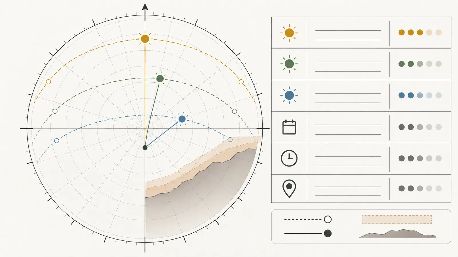
Use the lot’s latitude, longitude, local time zone and a documented date/time to obtain sun azimuth and elevation; then compare those outputs with the obstruction register at a small set of representative seasonal and occupancy checks. A generic “sun rises in the east” diagram is not enough for a site decision because the sun’s path changes by date, latitude, time and season.
Use the correct solar terms
Azimuth is the horizontal direction of the sun, measured clockwise from true north in the NWS dashboard’s convention. Elevation is the angle above the local horizon. The National Weather Service explains that solar noon is when the sun reaches its highest elevation and describes azimuth as an angular measurement from true north and elevation as an angular measurement above the horizon. The NWS Solar Info dashboard defaults to central Albuquerque but allows a location change and points users outside New Mexico to NOAA’s global calculator.
Do not treat clock noon as solar noon. Time zones, longitude, equation of time and daylight-saving time can shift the sun’s highest point away from 12:00 on the clock. Record both the local clock time and the calculator’s solar noon when making a check. If the question is household comfort at 4:00 p.m. local time, use 4:00 p.m. local time; if the question is maximum daily elevation, use solar noon. These are different design questions.
Enter a documented location and date
NOAA’s calculator accepts latitude, longitude, time zone, date and local time and reports solar noon, sunrise, sunset, azimuth and elevation. NOAA’s Solar Calculator explicitly warns that the calculator is no longer actively maintained, offers no technical support, and may differ from observed values because of atmospheric conditions and algorithm uncertainty. That limitation does not make the output useless for a preliminary register; it means the record must label it as a modeled planning input and the architect should use a project-appropriate analysis for design decisions.
For every sun-position row, record:
| Input | Example format | Check before handoff |
|---|---|---|
| Location | 39.7392° N, 104.9903° W | These are the lot or candidate-point coordinates, not a metro-area default |
| Date | 2026-12-21, 2027-03-20, 2027-06-21 | Use the actual year and note that representative dates are screening checks |
| Local time | 09:00, 12:00, 15:00, 17:00 | Confirm time zone and daylight-saving status |
| Time zone | Named U.S. zone and UTC offset | Verify the calculator did not apply a wrong or outdated setting |
| Output | Azimuth and elevation in degrees | Preserve the output and source, not just a rounded conclusion |
| Target | Winter daylight, summer glare, office hours or outdoor shade | Tells the architect why this row exists |
The coordinates above are an illustrative format only, not a recommendation for a real project. Replace them with the actual lot coordinates. If a site straddles a long parcel or has a meaningful slope, use the candidate pad point for the final screen and explain whether the solar calculator uses the parcel address, centroid or pad.
Choose representative checks deliberately
You do not need to record every minute of every day to make the first siting handoff useful. Choose checks that represent the design brief and decision boundary. A starter set is:
- Winter solstice or a project-relevant winter date at 9:00 a.m., solar noon and 3:00 p.m. local time.
- Near the spring or autumn equinox at the household’s key morning and afternoon times.
- Summer solstice or a project-relevant summer date at morning, solar noon and late afternoon.
- Any exact occupancy time that drives the brief, such as a home-office work block or outdoor dinner.
These are screening points, not a claim that the sun behaves only at those dates. PNNL notes that solar interaction changes throughout the year, and its overhang guidance says best practice considers heat gain throughout each hour and month rather than only solstice points. PNNL’s shading-analysis guidance is why the register should be used to select modeling questions, not to replace hourly or annual analysis.
For each check, use the obstruction sector that faces the sun. If the winter 9:00 a.m. sun azimuth is southeast and the closest obstruction is a tree spanning east-southeast through south, compare the ray to that tree. If the sun is north of an obstruction’s sector, do not claim the obstruction blocks it. If the elevation is below the local horizon because the sun has not risen or has set, mark the check “no direct sun above horizon,” not “blocked by tree.”
Treat sunrise and sunset as sensitive checks
Low sun near the horizon is especially sensitive to terrain, buildings, tree branches, camera height and small north errors. The register should call out when an obstruction is within a few degrees of a sunrise or sunset ray rather than presenting a binary answer. If the design brief depends on a low-angle dawn or late-afternoon view, the architect may need a detailed site and façade model.
At low elevations, a small obstruction-angle change can move the result from apparently clear to apparently blocked. The correct response is to preserve the uncertainty and ask whether the room actually needs direct beam sun at that time. A living room may benefit from diffuse daylight even when direct sun is blocked. A bedroom may benefit from avoiding direct dawn sun. A porch may need shade at a time when interior glazing does not.
Separate direct beam from diffuse daylight
PNNL distinguishes direct beam solar radiation, which contributes to glare and intense surface heating, from diffuse radiation, which can provide pleasant natural light. PNNL’s sunlight characteristics discussion is a reminder that “blocked direct sun” does not mean “dark room,” and “clear direct sun” does not mean “comfortable room.”
Your obstruction register should therefore have two interpretation columns: “direct-beam question” and “daylight/view question.” For example, a tree canopy may intercept a direct winter ray but still allow diffuse light and a filtered view. A west-facing window may have a clear horizon but create glare and overheating at 5:00 p.m. A neighboring wall may block the horizon and reflect light into a courtyard. The architect should choose the relevant performance metric: daylight autonomy, glare risk, solar heat gain, view, thermal comfort, or a combination.
Verify the north and time inputs before trusting an output
The most damaging errors are often administrative rather than mathematical: a calculator set to the wrong time zone, a map bearing treated as true north, or a date interpreted in UTC instead of local time. Use a simple reconciliation checklist:
- Does the solar calculator location match the candidate pad rather than a city default?
- Does the time zone match the actual city, state and date?
- Is daylight-saving time correctly represented for the observation?
- Does solar noon occur at a plausible local clock time for the longitude?
- Does the azimuth convention say degrees clockwise from true north?
- Did the obstruction bearing use the same north basis?
- Were all distances and heights kept in the same unit system?
- Does a field observation of morning or afternoon direction broadly agree with the output?
If one answer is no or unknown, flag the row. A reconciliation check is not a new measurement; it is a way to prevent a clean-looking but mismatched comparison.
Compare candidate house locations without overclaiming #
Compare candidate pads using the same input rules, the same seasonal sun checks and the same household priorities; select the pad for professional modeling, not by adding unsupported points to a “solar score.” The best pad may be the one with slightly less direct winter sun if it has better access, drainage, wildfire safety, privacy, utility routing, local compliance or summer comfort. Solar evidence should make tradeoffs explicit rather than pretending to settle the whole site.
Build a decision matrix, not a single ranking
Use a qualitative matrix first. If you later use weights, disclose them as household preferences rather than objective performance. The following template keeps solar access beside the other site decisions:
| Criterion | Pad A evidence | Pad B evidence | Confidence | Owner of next check |
|---|---|---|---|---|
| Winter living-room direct-beam opportunity | South sector open to 12°, T-01 high case reaches 15° | South sector partly open; ridge angle 8° | Medium | Architect to model window and finished-floor height |
| Summer late-afternoon glare exposure | West sector open above 6°; low-angle sun likely | West sector blocked by building B-02 at 11° | Medium | Architect to compare glazing, shading and room use |
| Diffuse daylight and view | East tree canopy may filter view | Clearer east horizon, less privacy | Low to medium | Architect to test plan and window locations |
| Future obstruction risk | Neighboring lot’s envelope unknown | Existing ridge stable; tree growth uncertain | Low | Local authority, surveyor or arborist as applicable |
| Site and jurisdiction constraints | Access and grade unresolved | Better access but local height question open | Low | Civil professional and named city/county department |
| Next decision | Model A and one rotated option | Obtain topography before modeling | — | Architect coordinates |
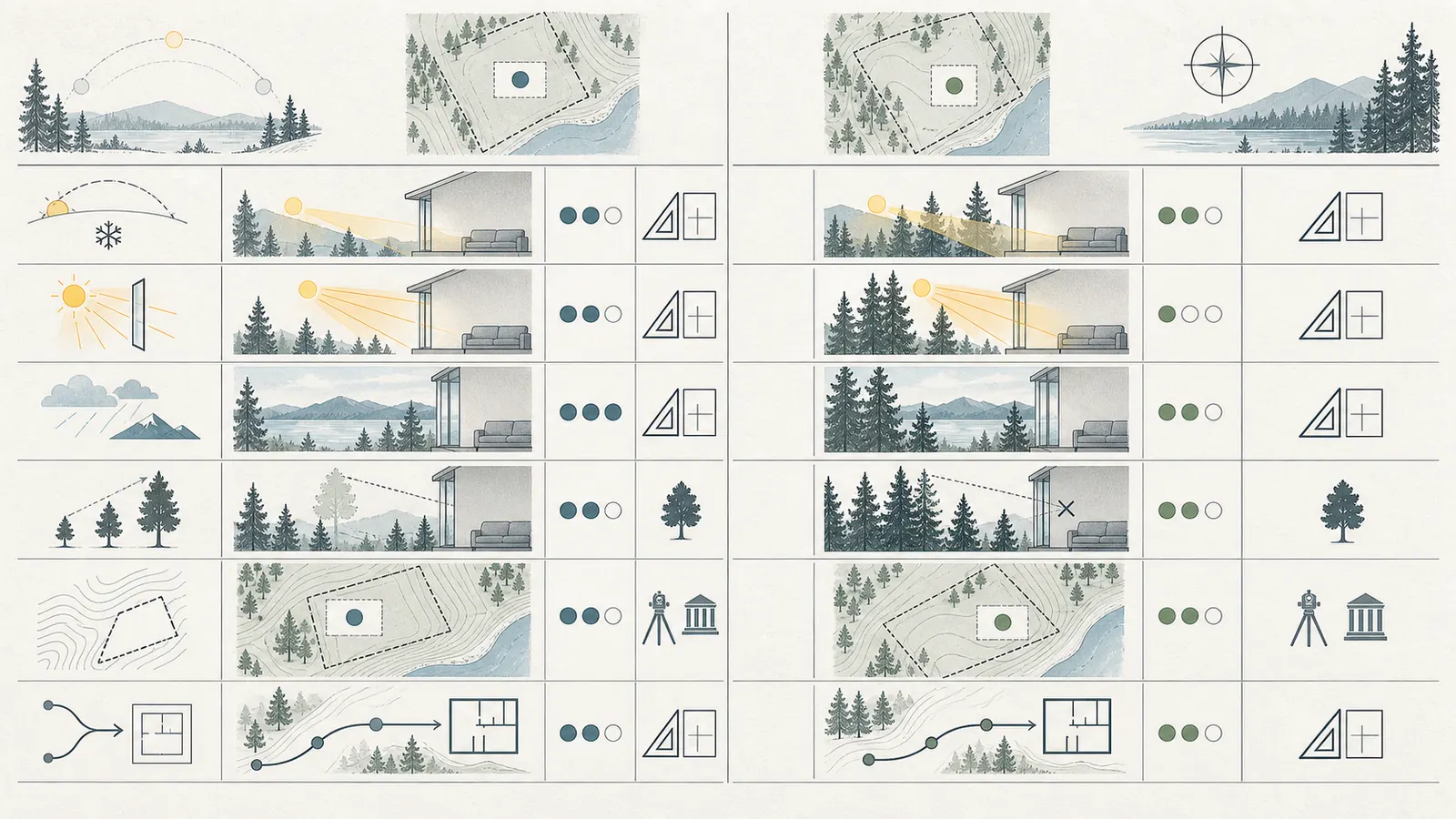
The matrix is useful because a solar advantage is only meaningful when tied to a room, time, orientation and confidence. If Pad A is “better solar” only because its elevation estimate is optimistic, the matrix exposes that. If Pad B is less sunny but is the only option that avoids a steep drive or an authority’s height limit, the architect can explore a compensating design instead of discovering the conflict after schematic design.
Use a simple confidence taxonomy
Confidence describes the input record, not the final design outcome:
- High: position and elevation come from a current survey or measured source appropriate to the decision; the north basis is named; the object is stable; the date and method are recorded.
- Medium: location is reasonably known, but height, canopy edge, season, or map basis has an estimate that could move the comparison.
- Low: the object is inferred from a distant photo, old aerial image, unknown map basis, unverified future condition, uncertain species or terrain model.
Do not average confidence labels into a percentage. One low-confidence obstruction can control the next action even if the other rows are high confidence. A low-confidence ridge on the south horizon may warrant a topographic survey; a low-confidence shrub on a façade with no planned glazing may be safely deprioritized after the architect confirms the plan.
Account for orientation tradeoffs
“Face the house south” is too simple for a real lot. PNNL describes a north-south-oriented home as a way to optimize solar exposure while minimizing overheating from low-angle east-west sun, but the same guidance says window and overhang placement and landscape shading must be considered. PNNL’s orientation guidance supports using an orientation as a starting option, not as a forced geometry when the lot or program points elsewhere.
The lot may force a diagonal house because of road access, slope, septic area, floodplain, view, privacy, fire access, utility easements, tree retention or local setbacks. A rotated home can still have a good room-by-room strategy if the architect places glazing, overhangs, fins, porches, screens and mechanical systems around the actual solar exposure. The design question is not whether every wall is aligned with a compass point; it is whether the resulting exposures are intentional and verified against the brief.
PNNL’s solar-control guidance recommends, when possible, avoiding direct sun through windows during the cooling season and minimizing east- and west-facing window area. The PNNL window and skylight guidance also describes windows as serving multiple functions—daylight, views, ventilation, access and solar heat gain—so minimizing exposure is not a universal command to remove windows. The architect must balance each opening’s function, climate and shading strategy.
Check more than trees
An obstruction register that lists only vegetation is incomplete. Use a category checklist:
- Existing and likely future neighboring buildings.
- Garages, sheds, barns, walls, fences and elevated decks.
- Ridges, slopes, berms, cut banks and forest edges.
- Utility structures or poles that may affect a narrow view sector.
- Seasonal equipment, stored materials or temporary construction that could mislead a visit.
- The future house itself, including second stories, porches and roof forms that shade yards or lower windows.
- Landscape proposals, replacement trees and planned screens.
Not all need the same measurement. The purpose is to avoid a blind spot and to assign the right next professional. A utility pole may matter to a narrow solar view but is not a tree-management question. A ridge may require topography. A neighboring building may require a jurisdiction-specific future-envelope question. A planned shade tree may be a design choice that the architect can model without treating it as an existing obstruction.
Do not confuse a solar comparison with a legal claim
This article does not evaluate solar easements, private nuisance, tree-removal rights, view rights, subdivision covenants, HOA rules, zoning envelopes, historic-district review or any other legal solar-access issue. Those questions depend on the actual city, county, state, title documents, private agreements and facts of the property. If one of those issues could change the siting decision, identify the jurisdiction and ask a qualified local professional for a written review.
The register can say “future obstruction or legal status unresolved.” It cannot say “the neighbor cannot block the sun,” “the tree must be removed,” or “the city will approve this orientation.” Do not present a map, calculator result or generic DOE guidance as a legal conclusion. The safe handoff is a list of exact questions, the document or authority that must answer each, and the deadline before the next design gate.
Hand off the record for schematic design and verify the next decision #
The handoff is complete only when the architect can trace each important solar conclusion back to a source, input and uncertainty, then state what will be modeled or verified next. Send the register, original photos, map or survey basis, solar-position outputs, candidate matrix and unresolved jurisdiction questions together. Ask for a written response that identifies whether the current pad remains viable, which alternate needs testing, and what evidence would change that conclusion.
Package the handoff as a small evidence set
Use a folder or shared project location with a readme. The readme should state the property city, state and county; the date range of observations; the candidate pad names; the true-north basis; the climate-zone source; the calculator or model used for solar positions; and the limitations. Use stable filenames and do not overwrite the original image or map source.
The minimum handoff contains:
- A site-base PDF or image with the source, date, scale and north convention.
- A candidate-pad plan showing reference points and provisional rectangles.
- The obstruction register with raw and derived fields separated.
- Original photos and a photo index tied to obstruction IDs.
- A seasonal sun-position table with location, date, time zone, azimuth and elevation.
- The decision matrix with confidence and next-owner columns.
- A short household brief naming the rooms, times and comfort priorities.
- A list of actual jurisdiction questions and the city, county, HOA or other responsible party for each.
- A clear note that the record is not a survey, energy model, legal opinion or construction authorization.
The architect should not have to guess which file is controlling. If the survey and homeowner map disagree, mark both and ask the design team to resolve the conflict. If a professional supplies a revised site model, preserve the earlier version and record the revision date and reason. A substantive review date belongs to an updated model, not to a cosmetic renaming of the PDF.
Ask the architect for a specific comparison
A vague request such as “Can you check solar?” produces an equally vague response. Ask for a defined pre-schematic comparison:
- Model candidate pad A with the stated north basis and the household brief.
- Model the strongest alternate pad or a meaningful rotation of A.
- Show the room and window assumptions used for daylight, direct sun, glare and solar heat.
- Test the decision-sensitive obstructions under low, base and high geometry cases.
- Identify which inputs must be replaced by a current survey, topography, arborist review, local rule or more detailed analysis.
- State the next decision: continue with A, revise the orientation, test B, resolve a site constraint, or stop solar comparison until a prerequisite is complete.
DOE explains that building energy modeling helps architects quantify project-specific tradeoffs, including lots that cannot accommodate an ideal axis, nearby buildings that block light, local regulation constraints and competing client goals. It also says major orientation, height, floor-plan and façade choices are usually settled early enough that early modeling can help avoid undermining performance later. DOE’s architectural-design BEM explanation supports involving the design team before the footprint and glazing strategy harden.
Do not prescribe a particular software package or demand a numeric annual result before the project has a reliable base model. Ask what level of analysis fits the decision. The architect may use a solar study, shadow study, daylight analysis, energy model, site model, or several tools. The deliverable matters more than the brand: it should show assumptions, date, north, candidate geometry, seasonal conditions, tradeoffs and the next design action.
Verify the highest-consequence rows first
Verification should be risk-based. Start with rows that could reverse the pad decision:
- An obstruction angle close to a target winter or summer sun elevation.
- A north-basis disagreement between survey, GIS and compass.
- A ridge or neighboring building whose elevation is estimated rather than measured.
- A tree whose retention, growth, health or legal status is central to the design.
- A future condition that could change the house’s only useful solar sector.
- A local height, setback, tree or overlay question that could invalidate the assumed window or pad.
Rows that cannot change the design can remain approximate if the architect agrees. This is not permission to ignore them; it is a way to spend professional effort where it changes the next decision. Write the reason for deferring a row so the uncertainty does not disappear from the project memory.
Reconcile site constraints outside the solar register
The solar worksheet is one input to siting. Before selecting a pad, the design team should reconcile it with access, grading, drainage, utilities, septic or sewer constraints, flood and wildfire exposure, easements, setbacks, privacy, views, structural ground conditions and local approvals as applicable to the actual property. These subjects are outside this article’s solar scope, but they are common reasons an apparently ideal sun position cannot become the house location.
Name the actual authority for each local question. “Check zoning” is not a completed action. Use a row such as “City of Example Planning Department: confirm maximum building height for this parcel and whether rooftop projections are measured from existing or proposed grade; question sent 2026-09-08; written response pending.” If the parcel is in an unincorporated county area, use the county planning or building authority. If private restrictions matter, identify the HOA, declaration or title professional. The article cannot generalize a rule across U.S. jurisdictions.
Use the result as a design gate
At the end of the pre-schematic exercise, make one of these explicit decisions:
- Advance one candidate: The architect has a traceable north basis, enough site geometry for an initial model, and no unresolved obstruction likely to reverse the household brief.
- Advance two candidates: Solar tradeoffs are close or priorities conflict; the architect models both before the footprint, room placement or window schedule becomes fixed.
- Resolve evidence first: A survey, topographic source, arborist review, local rule, ownership question or time-zone/north correction could change the comparison.
- Change the brief: The household decides that winter direct sun, late-afternoon glare control, view, privacy or outdoor shade has a different priority, and the matrix is rerun.
Write the chosen gate and its owner in the register. A “next decision” column is valuable because it protects the work from becoming a static collection of photos. If the architect says “Pad B needs a daylight model after the survey,” record that exact handoff. If the homeowner decides that mechanical heating and cooling make passive heat secondary, record the changed priority rather than continuing to score winter sun as if it were still decisive.
Know when to stop using the worksheet
Stop treating the worksheet as sufficient when the question becomes permit-ready, legal, structural, or construction-specific. Examples include proving a required solar exposure, defining a property line, designing a retaining wall, deciding whether to cut a tree, checking utility clearance, sizing an overhang attachment, approving a roof or foundation, or guaranteeing indoor temperature and energy use. Those require the appropriate local professional, authority, survey, analysis or approval.
Also stop when the data conflict. A disagreement is useful if it is recorded, but it should not be averaged away. If the map says the ridge is 8 degrees and the field estimate says 15 degrees, carry both values, explain the sources and request resolution. If the phone compass and survey north differ, do not choose the more convenient bearing. If a neighbor’s future construction is speculative, do not use it as a certainty; model a clearly labeled scenario only if the decision warrants it.
Use the completed worksheet as a living design record #
Keep the solar register active through schematic design, because the meaning of an obstruction changes when the house height, room placement, window geometry, overhangs and landscape strategy change. The purpose is not to create a one-time “sunny lot” certificate; it is to preserve the reasoning behind a siting decision and make later changes visible.
Update only when something substantive changes
Update the record when a survey changes the north or elevation basis, the house pad moves, the massing or window plan changes, a tree is assessed or changes materially, a neighboring building changes, a local authority provides a written answer, or the design team replaces the screening analysis with a more detailed model. Record the actual change and its effect.
Do not update the date simply because the article or folder was reopened. A current review date should mean that someone checked the relevant inputs and contribution. In the project register, distinguish “observed on,” “modeled on,” “professionally reviewed on,” and “document last edited.” This makes seasonal or time-sensitive evidence easier to interpret.
Preserve sensitivity alongside the preferred option
When the architect chooses Pad A, keep the reasons Pad B was not selected and the sensitivity that supported the decision. Future changes may make the alternate relevant. For example, a high-case tree height might initially be unresolved, but later an arborist’s report could show that the tree is stable and smaller than assumed. Or a neighboring addition may change the west obstruction. A well-maintained record lets the team rerun the comparison without reconstructing the original assumptions.
The record should say whether the preferred option depends on a design feature. “Pad A works only with a south overhang, a lower west glazing ratio and living-room placement on the southeast corner” is more valuable than “Pad A has best solar.” PNNL’s guidance explains that architectural shading can block summer direct radiation while allowing winter solar gain when designed properly, but sizing and effectiveness depend on latitude, orientation, height, width and the hours and months being optimized. PNNL’s architectural-shading guidance is a reason to preserve those dependencies in the handoff.
Use clear language in the final project note
The final note can be short:
Candidate Pad A is advanced to schematic comparison with Pad B. The site basis is the survey north arrow dated [date]. The most decision-sensitive obstruction is T-01 at [bearing sector], with a first-pass angle range of [low–high] degrees from [distance and height assumptions]. Seasonal checks at [dates/times] will be reviewed by the architect for the living room, office and south outdoor space. The register does not establish boundaries, legal solar access, tree-removal rights, code compliance, structural design or predicted annual energy use. Before the next gate, [owner] will obtain [survey/topography/local written response/model] and the architect will report whether the preferred pad changes.
That wording keeps the result useful and modest. It communicates a decision, evidence, uncertainty, responsibility and next action without claiming that a homeowner’s observation is a professional certification.
Final homeowner checklist
Before sending the package to the architect, confirm:
- The actual city, state and county are named.
- The candidate pad points and provisional footprints are named.
- The climate-region source and code-climate-zone question are separated.
- The north basis says true, grid or magnetic, with a source and date.
- Latitude and longitude refer to the lot or candidate point.
- Time zone and daylight-saving status are recorded for solar checks.
- Obstructions include buildings, terrain and future questions, not only trees.
- Each important row has bearing, distance, height difference and units.
- Raw observations are separate from calculated angles and interpretations.
- Tree rows distinguish leaf-on, leaf-off, evergreen or unknown conditions.
- Solar-position rows include date, local time, azimuth and elevation.
- The formula and illustrative or measured inputs are visible.
- Sensitivity is shown where height, distance or north is uncertain.
- Confidence labels explain why an input is high, medium or low.
- Photos and maps retain original files and source information.
- Local questions name the actual city, county, HOA or other responsible party.
- No row claims a legal right, survey result, permit outcome or construction approval.
- The architect has a defined comparison and a next-decision request.
If the checklist is complete, the practical outcome is not a promise of solar performance. It is a defensible handoff: the design team can see what the lot offers in each season, which obstructions are likely to matter, which assumptions are fragile, and whether another house location or orientation deserves testing before schematic design becomes expensive to change.
Cite this guide
Brictale. “How to Map Seasonal Solar Obstructions Before Siting a New Home.” Published 2026-09-21; updated 2026-09-21.
https://brictale.com/build/design/map-seasonal-solar-obstructions-before-home-siting · Read the Markdown version
Original contribution: Seasonal solar-obstruction register and siting worksheet. A homeowner-ready record for comparing candidate house pad points by location, true-north basis, obstruction geometry, seasonal sun positions, confidence and architect handoff.
Sources and scope
Evidence behind this page
- The U.S. Department of Energy passive-solar guide says windows should face within 30 degrees of true south and should not be shaded during the winter 9 a.m. to 3 p.m. period when applying its passive-solar design guidance.
Guide to Passive Solar Home Design
DOE educational guidance for passive-solar homes; the 30-degree and winter-hours statements are design guidance, not a universal daylight entitlement or local code requirement.
Accessed · Link to this claim - DOE describes passive solar design as using low winter sun for warming and high summer sun for deflection, with orientation, elevation, room layout, materials and surroundings affecting performance.
Guide to Passive Solar Home Design
General DOE passive-solar explanation; it supports seasonal comparison but does not predict a particular lot or house.
Accessed · Link to this claim - PNNL Building America explains that natural-comfort orientation considers the home shape, climate, sun exposure and shading, and that windows and overhangs need to be placed to control solar exposure.
PNNL Building America educational material funded by DOE; it is not formal training, certification or a site-specific design approval.
Accessed · Link to this claim - PNNL recommends, where possible, avoiding direct sunlight through windows during the cooling season and minimizing east- and west-facing window area as part of solar heat-gain control.
Shading and Solar Control for Windows and Skylights
Building America resource guidance for window and skylight solar control; the recommendation must be balanced with daylight, views, ventilation, climate and the project brief.
Accessed · Link to this claim - PNNL describes the sun as arriving mostly from the south in winter and from east and west in summer in the contiguous United States, and says summer east- and west-facing windows can receive much more solar heat per square foot than south-facing windows at those latitudes.
Shading and Solar Control for Windows and Skylights
PNNL discussion and illustrative example for the contiguous United States; it is not a parcel-specific hourly result.
Accessed · Link to this claim - PNNL says deciduous trees on the south side can block summer sun while allowing winter solar heat gain, while large trees placed at a distance can block lower-angle east or west sun and preserve some views and breezes.
Shading and Solar Control for Windows and Skylights
PNNL landscape-shading guidance; actual species, mature size, health, wildfire risk, root effects, ownership and local rules require project-specific review.
Accessed · Link to this claim - PNNL says shading guidance should account for latitude, window orientation, the height between the window and overhang, climate and hourly or monthly heat gain rather than relying only on solstice rules of thumb.
Shading and Solar Control for Windows and Skylights
PNNL guidance on architectural shading analysis; it supports handing a site record to a designer, not homeowner sizing of structural attachments.
Accessed · Link to this claim - The National Weather Service solar dashboard defines solar noon as the time when the sun is at its highest elevation and describes azimuth as an angular measurement from true north and elevation as an angle above the horizon.
NWS Albuquerque dashboard documentation; its default is central Albuquerque but the dashboard describes changing the location, and it links to a NOAA calculator for locations beyond New Mexico.
Accessed · Link to this claim - NOAA’s solar calculator accepts latitude, longitude, time zone, date and local time and reports solar noon, sunrise, sunset, azimuth and elevation, while warning that it is not actively maintained and that atmospheric conditions and algorithm uncertainty can make observed values differ.
NOAA/GML calculator interface and its explicit limitation notice; use the output as a planning input to be checked by the design team, not as a survey or guaranteed observation.
Accessed · Link to this claim - NOAA NCEI explains that magnetic declination is the angle between magnetic north and true north, varies with location and time, and is needed when converting a compass reading to true north.
Help: Magnetic Bearing Calculator | NCEI
NOAA NCEI geomagnetic guidance; a compass reading is not a substitute for the north reference on a survey or site plan.
Accessed · Link to this claim - DOE Building America describes climate regions using heating degree days, average temperatures and precipitation and provides county-oriented climate guidance for building practices.
DOE Building America climate-region guidance; the applicable code climate zone, local amendments and project energy pathway must be confirmed for the actual jurisdiction.
Accessed · Link to this claim - DOE says building energy modeling helps architects quantify project-specific tradeoffs, including lots that cannot accommodate an ideal axis, nearby buildings that block light, local regulation constraints and competing client goals, and that major orientation and façade choices are settled early.
Building Energy Modeling 101: Architectural Design Use Case
DOE architectural-design explanation of BEM; it supports early designer involvement but does not specify a required model for a particular residence or jurisdiction.
Accessed · Link to this claim - USGS distinguishes true north, grid north and magnetic north on topographic maps and notes that magnetic declination varies with time and position.
What do the different north arrows on a USGS topographic map mean?
USGS map-reading explanation; it is useful for checking conventions but does not replace a current project survey.
Accessed · Link to this claim